

TTK FG-SYS Installation Manual

1
FG-SYS DIGITAL UNIT
INSTALLATION GUIDE
June 2014 – Version 3.0
FG-SYS Products: FG-SYS_Inst_guide_UK_062014.doc

2
DESCRIPTION
The FG-SYS Digital system ensures an immediate detection and a precise localization of any liquid
leak (water, acids, bases, solvents, hydrocarbons) in industrial applications and buildings.
The system is composed of a FG-SYS Digital Unit, lengths of sense cables and accessories.
The FG-SYS Digital Unit is designed to be used with sense cables FG-EC (Water and Bases), FG-AC
(Acids), or FG-OD (Hydrocarbons and Solvents). The presence of a liquid on the sense cable starts an
audible alarm, as well as a luminous alert. The information of the fault is displayed on the LCD screen,
which specifies the localization of the initial leak point to the nearest meter.
Each sense cable is equipped with a microchip at female connector end. The digital unit questions
successively each cable; the microchip then transmits numerically ' the state ' of the cable to the digital
unit. Because of autonomy of each cable, several faults can be detected at the same time (but only
one fault per cable).
A digital unit can manage three circuits of sense cables; each one of these circuits has a maximum
capacity of 40 sense cables of 15 meters, or 600 meters maximum per circuit. In addition to the
presence of a liquid, the system detects and locates any fault of cable break on the circuit of cables.
The FG-SYS Digital Unit is available in rack-mounted version (FG-SYS E), or wall mounted version
(FG-SYS F), with a metal enclosure.
The keyboard (of thirteen buttons) on the front face makes it possible to configure the system:
Nominate the zones for detection (by allotting a name to each sense cable), choose and configure for
the set-up (relays, serial communication), setting the parameters of the system (language, adjustment
of the time, date, protection code).
The green luminous witness, or red, indicates the state of the digital unit under surveillance mode or
alarm. The button on the right (ECS) allows the manual acknowledgement of the sound alarm, the
validation of an operation, and the return to the previous screen. The last thirty defects are kept in
memory and their description is accessible in the historical menu.
FG-SYS also has a general test function. The Digital Unit indicates the number of sense cables
installed on a circuit, the length of each sense cable, the nominated zones, associated sense cables,
as well as the overall length installed.
In order to explore the fault information, several tools are available. The FG-SYS digital unit is
equipped with eight configurable dry contacts: the choice of dry contact is associated with a cable and
the type of fault (leak, discontinuity, or both). Two independent serial links of type RS232/RS485, with
a JBUS/MODBUS communication protocol, are used for the connection to a supervisor.
This document is downloaded in our web sites: www.ttkuk.com; www.ttkasia.com;
www.ttkcanada.com; www.ttk.sg; www.ttkusa.com
The information contained in this document can be the subject to modifications without notice. This information and
diagrams were drawn up carefully, however TTK UK Ltd., TTK Asia Ltd. or TTK S.A.S. cannot guarantee that the
provided information does not contain any error or omission and cannot accept any comparative responsibility with
which the information is used. No part of this guide can be reproduced or transmitted without the express and written
permission from the Companies TTK UK Ltd., TTK Asia Ltd. or TTK S.A.S.
FROG-SYS and TOPSurveillance are trademarks of TTK S.A.S..

3
INDEX
CERTIFICATIONS
I FG-SYS DIGITAL UNIT INSTALLATION
1. Fixing the Digital Unit
2. Electrical Characteristics
3. Electrical Connection of the FG-SYS
3.1. Connection of the FG-SYS Digital Unit to the Earth
3.2. Connection of the Power Supply Cable
3.3. Connection of the Leader Cable FG-CLC
3.4. Connection of the Relays
3.5. Connection of the Serial Cable
3.6. Closing of the FG-SYS Digital Unit (wall mounted version) metal enclosure
II SENSE CABLE AND ACCESSORIES INSTALLATION
1. Sense Cable Installation
1.1. Hold down clips and cold adhesive with CFC-100
1.2. Installing Sense Cables FG-EC, FG-AC and FG-ECX
1.3. Installing Hydrocarbon and Solvents Sense Cable FG-OD
1.4. Identification or Labeling with ES-EC Tags
2. Jumper Cable FG-NC Installation
3. Accessories Installation
3.1. FG-DTCS Addressable Box
3.2. FG-DCTL– “Cut-to-Length” Addressable Box
3.3. FG-DTC, TTK Bus Diversion
3.4. FG-DOD, OD Bus Diversion
3.5. End Termination Plug
III STARTUP OF THE SYSTEM
1. Powering of the FG-SYS Digital Unit
2. Standby Mode
3. Communication Configuration
IV TEST PROCEDURES
1. Function Test
2. Test of Leaks
3. Test of Cable Break
4. Drawing FG-MAP
V MAINTENANCE – FAULTS FINDING
1. Checking the System
2. Maintenance of the System
2.1. Replacement of a sense cable
2.2. Precaution for use and storage
2.3. Addition of sense cables on an existing circuit
2.4. Addition of a new circuit of sense cables
3. Trouble Shooting Guide
APPENDIX
Connection of Digital Unit FG-SYS E or FG-SYS F (Wall or Rack version)

4
CERTIFICATIONS
Electromagnetic Compatibility E.M.C.
FG-SYS E (FROGSYS E) and FG-SYS F (FROGSYS F) are in conformity with the requirements of the
generic harmonized European standards:
IN 50081-1 (92) for the emissions
IN 50082-1 (92) for immunity
Report/ratio of tests n° 8080612-CQPE/1 of the 14/09/1998
National laboratory of Tests 1, rue Gaston Boissier - 75724 Paris Cedex 15 – France - EU
Requirements Safety German
FG-SYS E (FROGSYS E) and FG-SYS F (FROGSYS F) are in conformity with the requirements of the
German safety requirements.
IEC 601010-1/A2: 1995 Report/ratio of tests n°01410051446
FG-SYS F: Certificate n° Al 00 08 28525 003
FG-SYS E: Certificate n° B 00 08 28525 004, dated on 08-10-2000 Bauart (B = Bauart) - Gs (Al = Gs)
TÜV Product Service GmbH
Mergenthalerallee 27, D - 65760 Eschborn – Germany - EU
Functional Test Certificate
Functional tests of FG-SYS, Liquid Leak Detection and location System, according to Test Report n°
041101971, dated on the 9th of November 2004.
FG-SYS has been tested by AdvEOTec Laboratory: AdvEOTec S.A.S.
6-8, rue Closerie, Lisses, CE5270 - Clos aux Pois F-91052 Evry Cedex – France - EU
Tel.: +33160864361 – Fax.: +33160864387- www.adveotec.com – Email: contact@adveotec.com
ATEX Certificate
Equipment intended for use in explosive atmospheres, following the Directive 94/9/EC
Type Examination Certificate number: LCIE 05 ATEX 6065 X
CE II 1/ G SYST
EEx ia/[ia] IIC T6
UL Certifications
Under the File S9100, the Control Number assigned by UL: MW34
Product Identity: "PROCESS MANAGEMENT FG-SYS EQUIPMENT"

5
I. FG-SYS DIGITAL UNIT INSTALLATION
1. FIXING THE DIGITAL UNIT FG-SYS (E) OR (F)
Digital Unit FG-SYS E is used in Rack Mounted Version, in a bay or a cupboard 19 '''. It is advised
to envisage a site with height of the eyes to facilitate the reading of the display.
The dimensions are the following:
Height: 4U
Deep: 60 mm
FG-SYS (E) Rack Mounted Version
FG-SYS F Digital Unit is used in wall mounted version, with a metal enclosure. It is necessary to
open the front face of the unit, to get access to the electronic chart.
Use the accurate template included in the FG-SYS F box, in order to fix the digital Unit at the wall.
The dimensions are the following:
Wide: 200 mm
High: 250 mm
Deep: 100 mm
FG-SYS (F) Wall Mounted Version, with Metal Enclosure
6
2. ELECTRICAL CHARACTERISTICS
- Power Supply: 100-240 VAC - 0.35-0.2A - 50/60 Hz
- Max. Consumption : 15W
- Power Thermal Fuse 2x0.5 A on the secondary
- Rating : Class 2 not Inherent Limited
It is recommended electrically to protect the digital unit with a circuit breaker from 0.5 A.
Nine Dry Relays Characteristics:
Type : 1 RT Mechanical Signal Relay
Max. switching voltage. : 125 VAC / 60 VDC
Max. switching Intensity : 1 A
Max. switching capacity : 62,5 VA / 30 W
Working load min.: 5 VDC - 1 mA
Nominal load : 0,5 A à 125 VAC
1 A à 24 VDC
Sensing Cables:
- Rating : 12 VDC
- Nominal Voltage on the sense cable circuit (all voltages referred to Ground):
- 1A, 2A, 3A, 1B, 2B, 3B: 5 VDC
- 1D, 2D, 3D: 12.3 VDC
- 1C, 2C, 3C: 0 VDC (electrically connected to Ground)
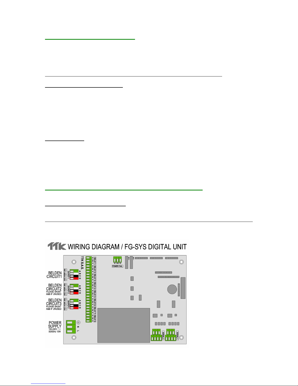
3. ELECTRICAL CONNECTION OF THE FG-SYS DIGITAL UNIT
Connections are done on the electronic board of the digital unit. The connector blocks are directly
accessible and removable (male parts) on the FG-SYSF and E; for the FG-SYS F (metal enclosure
wall mounted version), it is necessary to turn the key button of the front face to open it.
See Appendix n°1: “FG-SYS E or F Digital Unit Connection” page 57, and also available separately
inside the unit.
3.1 Connection of the FG-SYS Digital Unit to the Earth
7
CAUTION:
Respect the rules for Electromagnetic Compliance standards - (E.M.I.):
It is absolutely necessary to connect the back of the front face to the site (building)
earth.
The greenhouse cables and the screw n°3, with the identification "Earth ", are
available for this purpose.
3.2 Connection of the Power Cable
An power cable H07VV-F 3 x 1,5 mm², not provided by TTK, makes the electric connection of the
digital unit. Connect the cable on the male and female connector blocks 3 points, for this use; remove
the female to connect the power cable, and then place it back to the male.
The three terminals: L, N and Earth are indicated on the board.
Use the stuffing box n°3 for the cable.
(See Appendix n°1: FG-SYS E or F Digital Unit Connection)
Caution: Do not switch the FG-SYS Digital Unit On
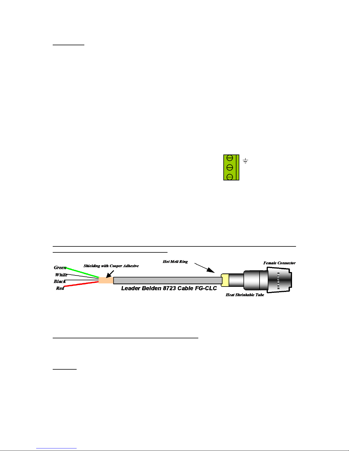
3.3 Connection of the FG-CLC Leader Cable
(See Appendix n°1: FG-SYS E or F Digital Unit Connection page 57, and also available
separately inside the unit)
Each circuit of sense cables is connected to the FG-SYS Digital Unit with a TTK Leader Cable (Belden
8723), ref. FG-CLC
Caution: An inversion between the two couples red + black, and green + white, damages the
electronic of the first connected sense cable.
Three circuits are available; first of all to use circuit n°1, then if necessary, following circuits.
Each circuit has a maximum capacity of 40 sense cables.
When the circuit n°2 is used: Remove the existing shunt between 2A and 2B.
When the circuit n°3 is used: Remove the existing shunt between 3A and 3B.
Caution:
To avoid the electromagnetic disturbances and emissions (ECM), it is necessary to connect the
shielding of the leader cable to the earth. Fix, using a metal cable clamp, the shielding of the
leader cable (available to the back)
(See Appendix n°1: FG-SYS E or F Digital Unit Connection, page 57.)
(Earth)
N (Neutral)
L (Live)

8
Metal Cable clamp
Cable
Shielding
Insulation
Earth
screw
3.4 Connection of the Relays
Nine dry relays are available on the FG-SYS Digital Unit with 3 points connector blocks. The electric
characteristics of these relays are the following:
Type: 1 RT
Max. Switching Voltage. : 125 VAC / 60 VDC
Max. Switching Intensity : 1 A
Max. Switching Capacity: 62,5 VA / 30 W
Working load min.: 5 VDC - 1 mA
Nominal load : 0,5 A à 125 VAC
1 A à 24 VDC
You can configure each of the relay with the “Configuration” Menu (ref chapter III 3.2) .
Relays Configurations are the following:
- Normally Open (NO) or Normally Close (NC), depending on the wiring
- Default associated: Leak, Cable Break, Leak or Cable Break
- Associated cable : cable number
Power supply check contact:
An additional contact (not configurable) is available for checking the presence of power.
PLEASE NOTE THAT THESE RELAYS ARE AVAILABLE FROM THE PCB OF THE CENTRAL UNIT.
They should not be confused with the optional Reed-relays Extension Boards described on page 35.
3.5 Connection of RS232 - RS422/485 serial links
The serial links are used for RS232/RS422/RS485 JBUS/MODBUS communication; they are available
via the two connectors located above the power supply. (Refer to appendix 1.)
To configure the serial connections, follow the instructions in section III 3.2.
3.6 Closing the FG-SYS F Digital Unit
All connections being finished, close the FG-SYS F Digital Unit. Fix the part of the unit containing the
circuit board on the part fixed at the wall. Be careful to the various cables connected and the flat
ribbons during closing the front door. Turn the button to fix the door closed.
For the rack version (FG-SYS E), we recommend to fix the various cables to the bay.
9
II SENSE CABLE AND ACCESSORIES INSTALLATION
FG-SYS System is modular. All the sense cables and accessories are pre-terminated with both male
and female connectors. This makes the installation quick, easy, and safe.
We recommend drawing a precise map of all zones to be fitted with sense cables, ensuring that all
installation zones are clean and dry before installation.
1. SENSE CABLE INSTALLATION
1.1 Installation: Hold Down Clips with Adhesive
The sense cables are fixed on the ground by fixing clips, type CFC-100.
The first stage of the installation consists in sticking these clips on the ground using the provided
adhesive (3M cold Glue).
Recommendations:
1. Ensure the cable sticks correctly to the earth, alternate the direction of the clips on the earth.
2. The clips must follow the drawing of the sense cables and be spaced approximately 1 metre apart.
3. Wherever there is a curve of the trajectory, stick 1 clip the entry point and a second at the exit point
of curve.
4. Please wait for the clips to be completely dry (three to four hours), before installing the sense
cables.
5. When fixing the sense cables into the clips, keep a length of approximately 10 cm between the
connector and the clip.
Hold Down Clips with Adhesive (ref.: CFC-100)

10
1.2 Installing sense cables: FG-EC, FG-AC and FG-ECX
Unroll the entire length of the sense cable and place in the clips fixed on the floor before
installation.
Caution: Start with the right way of the sense cables installation.
The FG-CLC leader cable, connected to the FG-SYS Digital Unit with a female connector, at its
extremity. The beginning of the sense cable thus corresponds at its extremity with a male
connector.
1. Connect the first sense cable to the leader cable, coming from the FG-SYS Digital Unit
2. It is recommended that you avoid placing the cables in direct contact with the jacks (on the raised
floor), the cable trays, any other obstacles...
3. Take care to circumvent the air-conditioning system (at a distance of approximately 50 to 75 cm), to
avoid false leak alarms related to harmless water projections.
4. All partitions must be fitted with pre-determined neutral Belden 8723 cables: type FG-NC (1 or 3
metres).
5. Once the sense cables are fixed with clips, their length must be maintained along the flooring or
ceiling in a closed retention tray, etc…
6. ES-EC tags must be placed along the length (packet of 40 tags) and spaced approximately every 4
metres.
7. Place a new length of sense cable (a pre-termined neutral Belden 8723 cable and finish the circuit
with a modular end termination plug.
1.3 Installing hydrocarbon and solvent sense cables: FG-OD
DESCRIPTION
The Oil & Gas FG-OD detection cable from TTK allows for the fast detection of any leaks of
hydrocarbon liquids. The presence of a real liquid leak, hydrocarbon or solvent, activates an audible
alarm, and detailed information is displayed on the Digital Unit with the hour, date, and type of fault:
leak or cable break. The dry contact related to the fault switches to the alarm position. This dry contact
makes it possible to drive an external alarm and be reported to a management team via BMS, remote
monitoring, solenoid valve, etc...
The dry contact remains activated as long as the alarm is present. Once the alarm has been cleared,
the relay returns to its initial position.
Due to ATEX regulations, FG-OD cables are using a different communication protocol, and they must
be connected to the system through a bus interface box FG-DOD. Up to 10x FG-OD cables can be
connected to one FG-DOD box.
The FG-OD kit contains:
1. A OD bus interface box for up to 10x FG-OD (FG-DOD)
2. A length of FG-OD sense cable (3, 7 or 12m)
3. A OD leader cable (FG-CLOD)
4. An OD end termination plug (FG-TMOD)
5. Hold-down adhesive clips
6. FG-OD kit installation instructions
CAUTION: All hydrocarbon sense cables must be installed in dry and clean areas
On the basis of the FG-SYS Digital Unit, unroll the lengths of sense cable while placing them in
the clips fixed on the ground.
Connection with a FG-SYS Digital Unit:
The set contains:
1. FG-SYS Digital Unit

11
2. One or more Digital FG-OD kits for FG-SYS (up to 40x FG-OD cables per circuit)
3. One or more additional FG-OD sense cables (max 10 FG-OD per FG-DOD)
To connect the FG-SYS Digital Unit, follow the FG-SYS installation instructions guide in chapter 1.3 of
this document.
FG-SYS haves a capacity of 40x FG-OD cables per circuit. Those cables must be connected to the
panel through a FG-DOD bus interface by groups of ten cables maximum.
Example: 4x FG-DOD with 10x FG-OD cables each = 40x FG-OD
Or: 8x FG-DOD with 5x FG-OD cables each = 40x FG-OD
Or: 2x FG-DOD with 10x FG-OD cables each + 4x FG-DOD with 5x FG-OD cables each = 40x FG-OD
CAUTION: The FG-SYS power supply must be switched off.
1. Connect the Belden 8723 cable to circuits 1, 2 or 3 in the FG-SYS Digital Unit:
On circuit no.1:
Green wire: Point 1A
White wire: Point 1B
Black wire: Point 1C
Red wire: Point 1D
2. Connect the other end of the Belden jumper cable to the INPUT points of the first FG-DOD interface
box.
3. Take the FG-CLOD 3.5 m leader cable and connect it to the following points of the ‘OD BUS’
terminal of the first FG-DOD interface box:
White wire: Point B
Black wire: Point C
Red wire: Point D
4. Fix the provided hold-down clips (1 clip per meter) and place the FG-OD sense cable in the clips.
5. Connect the FG-OD cable to the FG-CLOD leader cable, then add a second, third… FG-OD cable
(10x max) and put the FG-TMOD end plug at the end of the last FG-OD cable.
6. 7. Pour some light Naphta on the cable to simulate a leak alarm.
7. ‘OUTPUT ’ is reserved for the neutral cable going towards the next detection zones.
8. Proceed as with stage 2 for the second (and third etc.) FG-OD kits.
9. Note: on the last FG-DOD diversion box, a bridge must be installed on the unused ‘OUTPUT ’
terminal between points A and B.
OPERATION AND MAINTENANCE
The FG-OD sense cable is insensitive to the limited presence of conducting liquids (water, bases or
acids); FG-OD is also insensitive to any residual traces (lower than 35 ml) of non-conducting liquids
(hydrocarbons or solvents). The sense cable absorbs this limited presence of liquid and does not
react.
In the presence of a quantity (at least equal to 50 ml) of non-conducting liquids (hydrocarbons or
solvents), the FG-OD sense cable activates an alarm on the Digital Unit.
FG-OD cables are reusable after a limited contact with hydrocarbons. Immerse the cable in light
Naphta during 30 minutes, then remove and allow to dry for few hours.
12
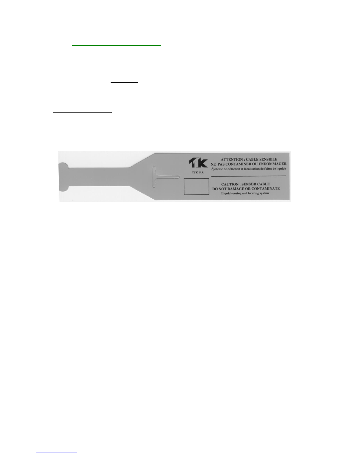
1.4 Labeling with ES-EC tags
Labels ES-EC indicate the presence of sense cables installed. Part of the label is reserved to the user
to note the distance rose, during water leak simulations.
1. Fix the labels every four meters on the circuit of sense cables.
2. Ensure itself of the good visibility of the labels.
Pack of 40 Tags, ref. : ES-EC

13
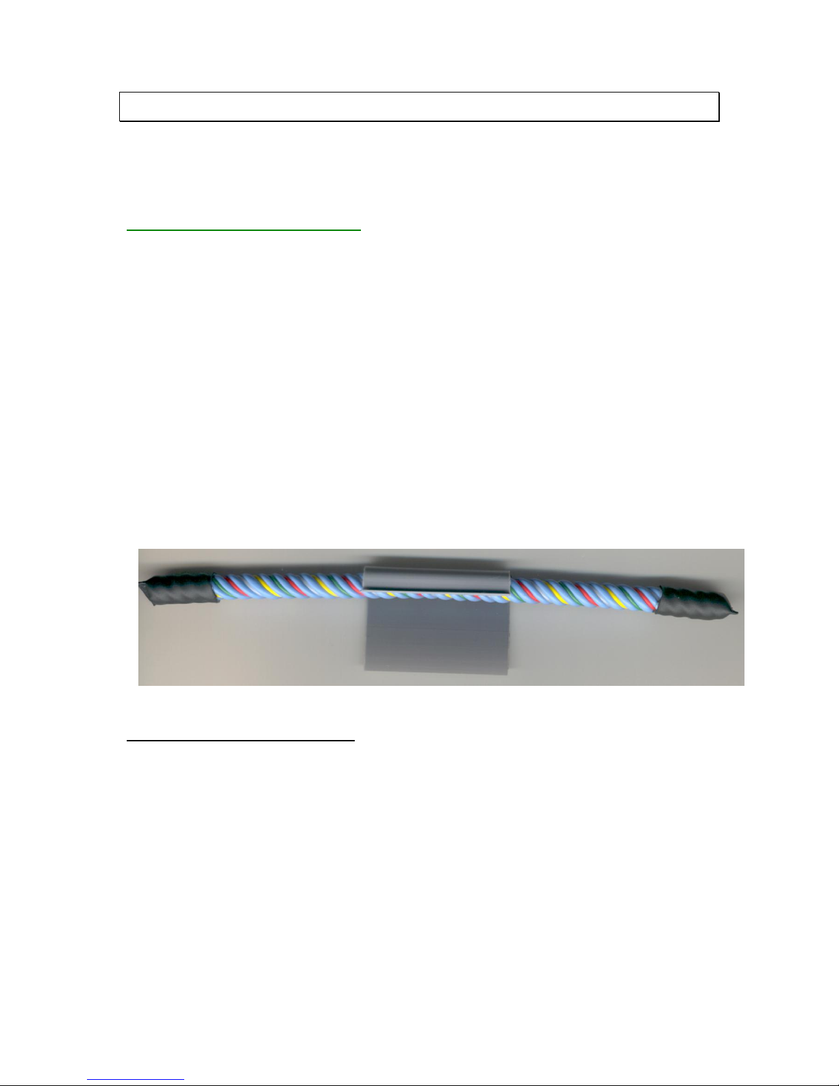
2. FG-NC JUMPER CABLE INSTALLATION
It can be necessary to use jumper cable for:
Pass from a zone of detection to another
Connect the Digital Unit to the first length of sense cable
Pass through rooms...
Note: for the passages of rooms, stop the passage of the sense cable with a product adapted to the
regulation and the architecture of your customer (partition firebreak, for example).
For a correct operation of the system, you have to use the following jumper cable:
BELDEN 8723 (LSZH, if required)
This jumper cable must be equipped with a male and female connector, in order to be compatible with
the TTK sense cables. The FG-NC Kit includes for this purpose the following material:
A male connector with its 4 contacts
A female connector with its 4contacts
2 heat-shrinkable sleeves
2 rings of hot melt
Notice for the realization of the jumper cable
Tools necessary:
Material to be stripped
Air Gun, with 800W power
Flat-nose pliers
Jumper Cable Connexion
The random jumper cable is installed. The beginning of the cable is the end coming from the digital
unit. Always start by making the connection at the beginning of the cable. The beginning of each
cable must be provided with a male connector and the end of the jumper cable with a female
connector.
At the beginning of the Belden jumper cable:
Jumper cable BELDEN 8723
Strip the external sheath on 20mm.
Strip the 4 wires on 5mm.
Do not cut the wire of shielding.
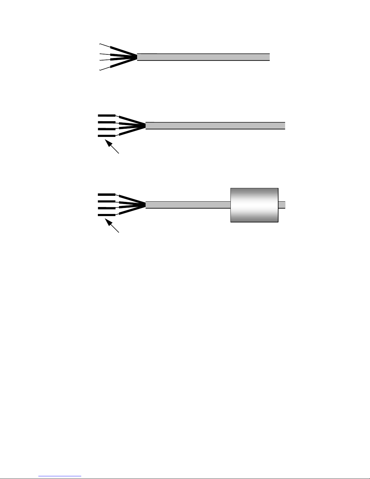
14
Jumper Cable BELDEN 8723
Crimp a male contact on each of the four wires. The wire of shielding is to be crimped in the same
contact as the black wire.
Jumper Cable BELDEN 8723
4 Male Contacts
- Put a 45 mm Heat Shrinkable Tube on the Jumper Cable.
Male Contacts
45 mm Heat Shrinkable Tube
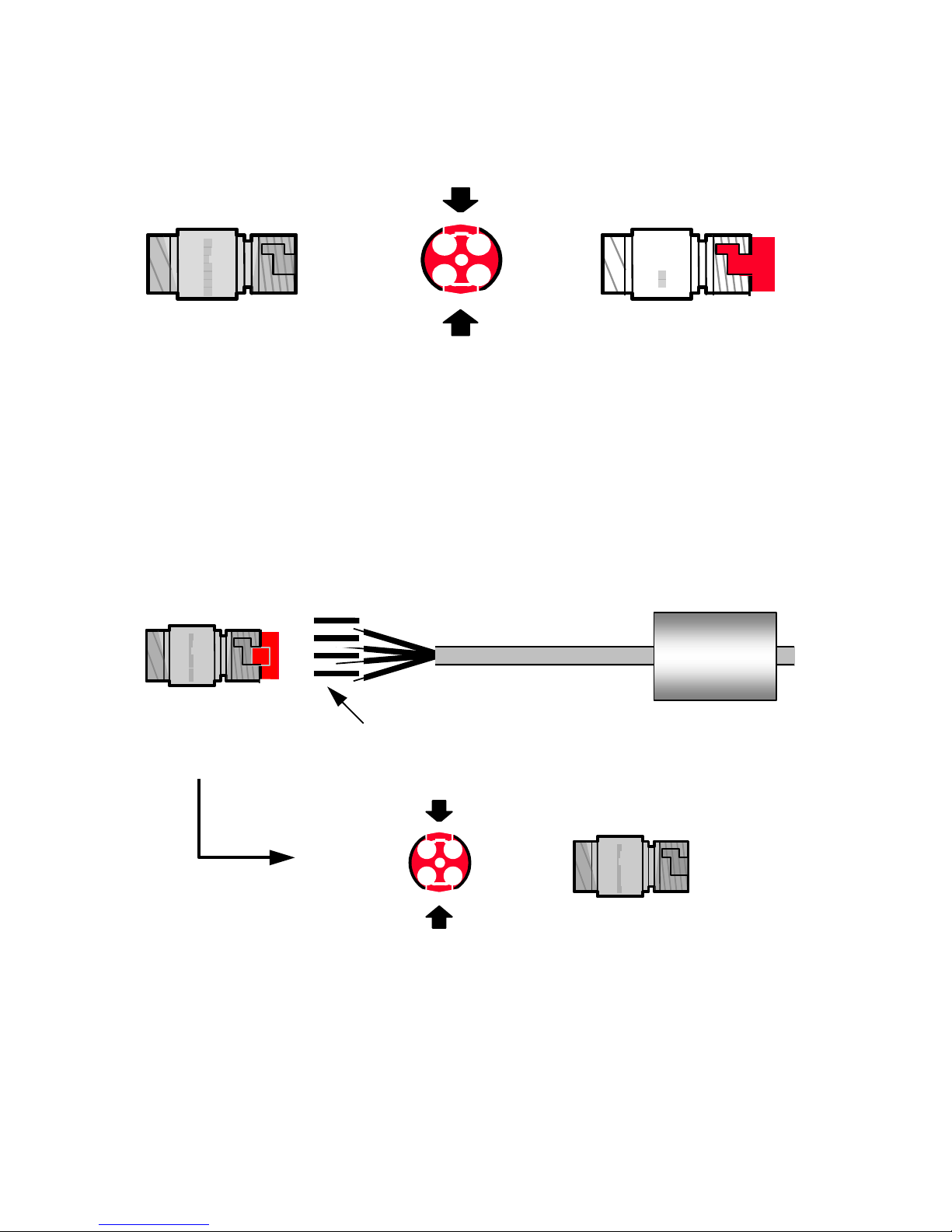
15
Prepare the Male Connector (the longest).
Encase the 4 contacts in the connector,
Draw the red plate while pressing on the sides (It is normal that it entirely did not leave).
Male Connector
C
L
I
P
P
E
R
Press and Draw
The red plate left
C
L
I
P
P
E
R
1
4
3
2
Insert the four contacts then, by respecting the following code:
Red Wire : point n°1 of Male Connector
Black Wire + Shielding : point n°2 of Male Connector
White Wire : point n°3 of Male Connector
Green Wire : point n°4 of Male Connector
And then, give the red plate to its place while pressing on the sides.
4 Male Contacts
45 mm Heat Shrinkable Tube
1
2
3
4
Male Connector
Insert the 4 Contacts
C
L
I
P
P
E
R
The red plate is re-entry
The contacts are blocked
Press and Draw
1
4
3
2
Green
White
Black
Red
C
L
I P P E R
The wires and contacts are now blocked. This process makes it possible to remove
the contacts very easily if necessary.
Caution: If the contacts are not entirely inserted in the connector, the red plate does
not return.
 Loading...