

TTK FG-NET Customer Operation & Installation Manual

1
Sep 2018 – Version 3.1.5
FG-NET_Operation & Installation Manual_UK_v3.1.5_201809.docx
OPERATION & INSTALLATION MANUAL
DIGITAL UNIT:
FG-NET

2
Sep 2018 – Version 3.1.5
FG-NET_Operation & Installation Manual_UK_v3.1.5_201809.docx
CONTENT
DESCRIPTION 4
CERTIFICATIONS 5
CHAPTER I: FG-NET DIGITAL UNIT INSTALLATION 7
1. MOUNTING THE FG-NET DIGITAL UNIT: E AND F 7
2. ELECTRICAL CHARACTERISTICS 8
3. ELECTRICAL CONNECTION OF THE FG-NET DIGITAL UNIT 10
3.1. Connecting the FG-NET Digital Unit to the earth 10
3.2. Connecting the power supply cable 11
3.3. Connecting the leader cable FG-CLC 13
3.4. Connecting the internal relays 14
3.5. Connecting the serial cable 15
3.6. Closing the FG-NET F Digital Unit 15
CHAPTER II: CABLE AND ACCESSORIES INSTALLATION 16
1. INSTALLING ADDRESSABLE SENSE CABLES 16
1.1. Hold-down adhesive clips 16
1.2. Installing sense cables: FG-EC, FG-AC and FG-ECX 17
1.3. Installing hydrocarbon and solvent sense cables: FG-OD 17
1.4. Labelling with tags 19
2. INSTALLING FG-NC JUMPER CABLES 20
3. INSTALLING CONNECTION ACCESSORIES 26
3.1. FG-DTCS - Addressable Box 26
3.2. FG-DCTL – “Cut-to-Length” Addressable Box 27
3.3. FG-DTC - TTK Bus Diversion 28
3.4. FG-DOD - OD Bus Interface 29
3.5. Installing end termination plugs 30
CHAPTER III: DIGITAL UNIT STARTUP 31
1. FG-NET DIGITAL UNIT – POWERING ON 31
2. MENUS 32
2.1. Setup 32
2.2. Events log 45

3
Sep 2018 – Version 3.1.5
FG-NET_Operation & Installation Manual_UK_v3.1.5_201809.docx
2.3. Cables 47
2.4. Help 56
2.5. SD Card 59
3. WATCHDOG 62
4. COMMUNICATION SETUP 63
4.1. General 63
4.2. Schematics 64
4.3. Modbus communication 66
4.4. TOPSurveillance™ Software 69
CHAPTER IV: EXTERNAL DEVICES 72
1. FG-RELAYS 72
2. FG-BBOX 74
CHAPTER V: TEST PROCEDURES 78
1. LEAK TESTS 78
2. CABLE BREAK TESTS 81
3. FG-NET MAP 82
CHAPTER VI: MAINTENANCE – FAULT FINDING 84
1. CHECKING THE SYSTEM 84
2. SYSTEM MAINTENANCE 84
2.1. Replacing a sense cable 84
2.2. Precautions for use and storage 85
2.3. Adding sense cables to an existing circuit 85
2.4. Addition of a New Circuit of Sense Cables (Circuits no.2 and/or no.3) 86
2.5. Removal of the system 86
3. TROUBLE SHOOTING GUIDE 87
Appendix 91
1. Digital Unit connection diagram and ratings: FG-NET E / F 91
2. Modbus Table 92
3. Commissioning guide 93

4
Sep 2018 – Version 3.1.5
FG-NET_Operation & Installation Manual_UK_v3.1.5_201809.docx
DESCRIPTION
The FG-NET Digital system ensures an immediate detection and the precise location of any liquid leaks
(water, acids, bases, solvents, hydrocarbons) in both industrial applications and buildings.
The FG-NET system is composed of an FG-NET Digital Unit, plus lengths of sense cables and accessories.
The FG-NET Digital Unit is designed to be used with TTK digital sense cables FG-EC (water and bases), FG-
AC (acids), or FG-OD (hydrocarbons and solvents). Different types of sense cables can be connected on
the same unit.
The presence of liquid on the sense cable triggers an audible alarm and activates the relevant relays. The
7’ (175mm) touch screen display shows the location of the leak to the nearest metre and details of the
fault in text format; an interactive installation plan (optional) highlights the location of the fault in real
time.
Each sense cable comes equipped with a microchip at the female connector end. The Digital Unit
questions each cable successively; the microchip then digitally transmits the ‘state’ of the cable to the
Digital Unit. Due to the autonomy of each cable, several faults can be detected at the same time within
the same circuit.
A Digital Unit can manage three circuits of sense cables; each one of these circuits has a maximum
capacity of 40 sense cables (15 metres I total), or 120 lengths of sense cable, that is 1,800 metres
maximum for an FG-NET unit. In addition to the presence of liquid, the system detects and locates any
faults in cable breaks within the circuit.
The FG-NET Digital Unit is available in a rack-mounted (19’ and 4U in height) version (FG-NET E), or a wall
mounted version (FG-NET F).
The touch-screen on the front face makes the setup of the system easy: For example, you can nominate
the zones for detection (by assigning a name to each sense cable), choose and configure the set-up
(relays, serial links), set the system parameters (language, time adjustment, date, user access levels, relay
setup, serial link connection, etc.).
The system's reaction time to faults on each sense cable is adjustable. It is possible to remotely isolate a
sense cable for up to 72 hours. The Digital Unit can store up to 5000 events in the event log.
In order to explore the fault, three types of interface with a centralized technical management system are
available: TCP/IP connection via an Ethernet port; JBUS/MODBUS protocol (Serial links - RS232,
RS422/485 output) and nine relays: eight of which are fully configurable and one to interrupt the power
supply.
This document is available on our web sites: www.ttkuk.com; www.ttk.fr; www.ttkasia.com; www.ttkaustralia.com;
www.ttk.sg.
The information contained in this document is subject to modifications without notice. This information and diagrams have been drawn up carefully, however
TTK UK Ltd., TTK Asia Ltd. or TTK S.A.S. cannot guarantee that the information provided does not contain any error s or omissions, and cannot accept any
comparative responsibility for which the information is used. No part of this guide can be reproduced or transmitted without the express and written
permission of the TTK UK Ltd., TTK Asia Ltd. or TTK S.A.S.
FG-NET and TOPSurveillance® are trademarks of TTK S.A.S.
5
Sep 2018 – Version 3.1.5
FG-NET_Operation & Installation Manual_UK_v3.1.5_201809.docx
CERTIFICATIONS
Electromagnetic compatibility E.M.C.
FG-NET E and FG-NET F fully conform to the requirements of generic harmonized European
standards:
EN 61000-6-3:2007 for emissions
EN 61000-6-2:2005 for immunity
ATEX Certification
FG-ECS, FG-ACS and FG-OD can be used in explosive atmospheres when connected to the FG-NET panel.
-30°C < T < +100°C
Equipment intended for use in explosive atmospheres, according to Directive 94/9/EC
Certification number: LCIE 05 ATEX 6065 X
International safety requirements
FG-NET E and FG-NET F are currently undergoing testing in order to conform to German and
American safety requirements.
IEC 61010-1:2010
6
Sep 2018 – Version 3.1.5
FG-NET_Operation & Installation Manual_UK_v3.1.5_201809.docx
Conditions of Use
FG-NET shall be installed indoor only in environments meeting the Rated Pollution Degree 2 or better
according to IEC 61010-1: Edition 3.
This panel contains soldered, non-replaceable and not-serviceable lithium battery. Please
dispose properly after removal, refer to the applicable laws in the country of installation and use!
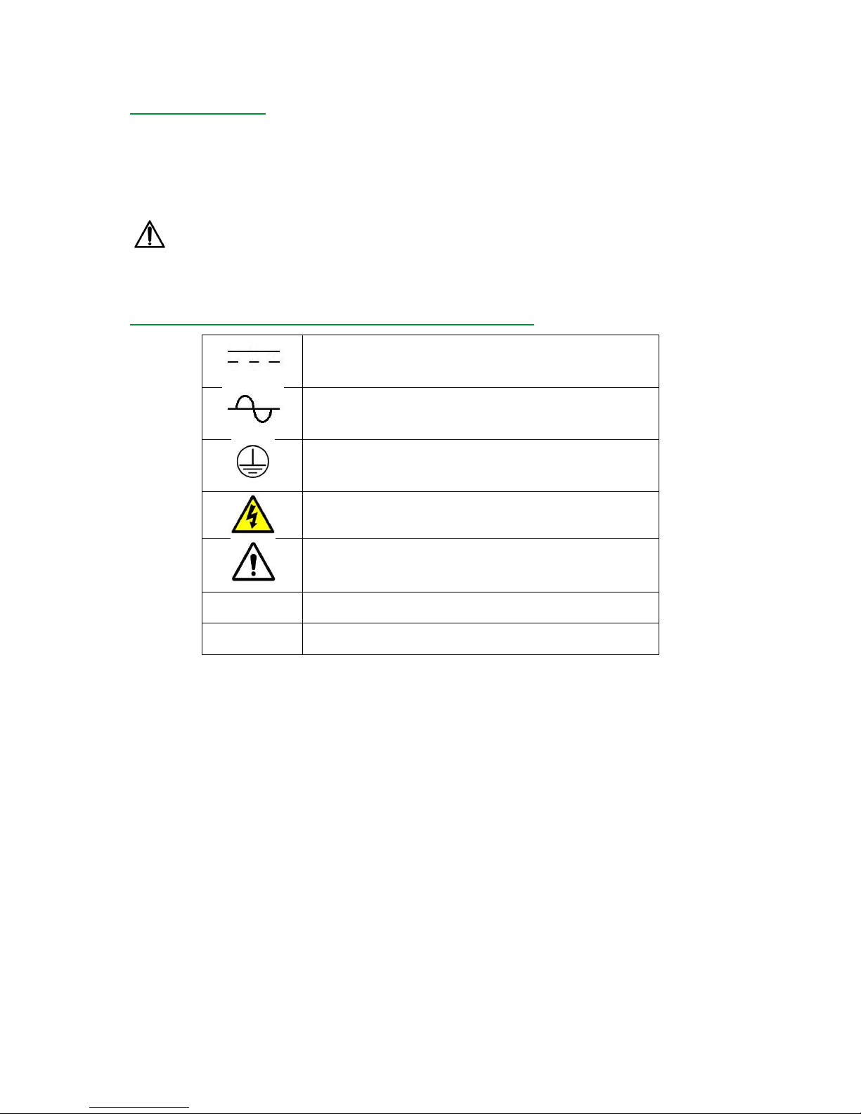
Symbols used in this document and on FG-NET panel
Direct current
Alternating current
Protective conductor terminal
Caution, risk of electric shock
Caution, risk of danger: please consult the current
document where this symbol is marked on the panel
L
Live
N
Neutral

7
Sep 2018 – Version 3.1.5
FG-NET_Operation & Installation Manual_UK_v3.1.5_201809.docx
CHAPTER I: FG-NET DIGITAL UNIT INSTALLATION
1. MOUNTING THE FG-NET DIGITAL UNIT: E AND F
The FG-NET E Digital Unit is available in a rack mounted version (in a bay or a 19’ casing).
It is advised to choose a location at eye-height level in order to facilitate reading the display.
The dimensions are as follows:
Width: 483 mm
Height: 177 mm
Depth: 74 mm
Weight: 3 kg
FG-NET (E) Rack mounted version
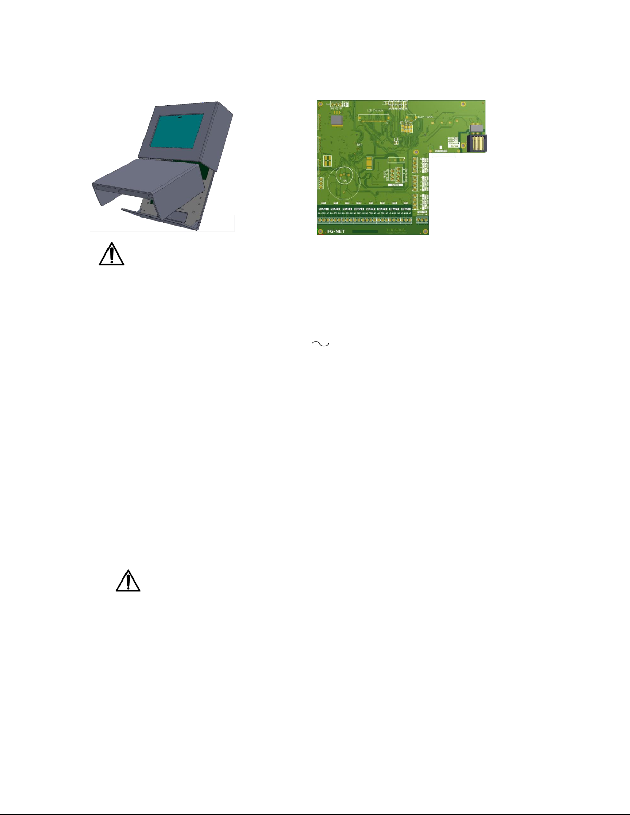
FG-NET F Digital Unit is also available in a wall-mounted version.
The dimensions are as follows:
Width: 228 mm
Height: 303 mm
Depth: 67 mm
Weight: 2.3 kg
FG-NET (F) Wall-mounted version
8
Sep 2018 – Version 3.1.5
FG-NET_Operation & Installation Manual_UK_v3.1.5_201809.docx
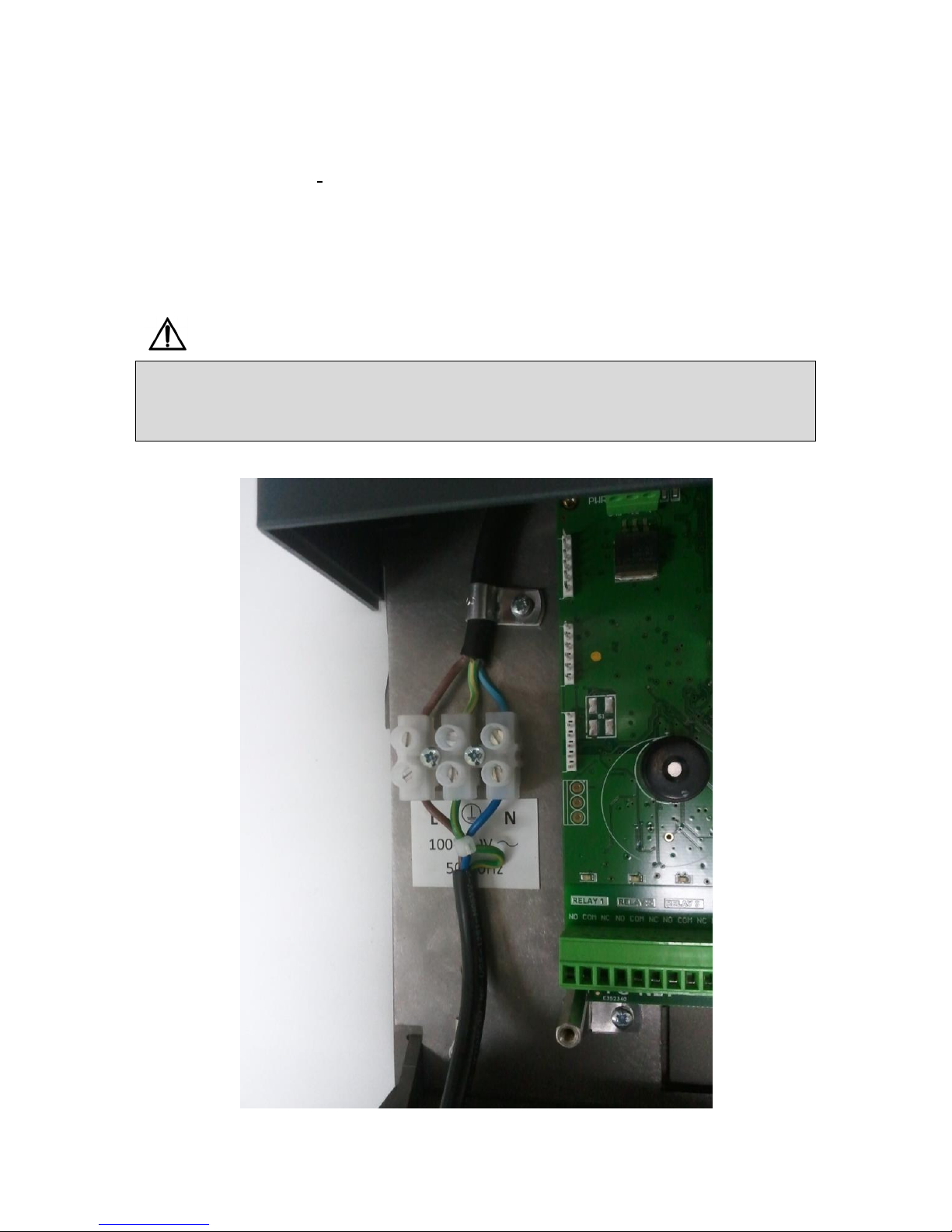
Open the cover of the wall-mounted Digital Unit in order to reach the motherboard which is fixed to
the interior of the casing (as shown below):
PLEASE DISCONNECT POWER PRIOR TO MOUNTING, OPENNING OR CONNECTING THE
PANEL TO ANY ELECTRIC CABLE.
2. ELECTRICAL CHARACTERISTICS
- Power Supply:
100-240V , 50/60Hz (1).
- Power Consumption: 36 VA Max.
- Input Current Rating: 1.3 A
- Overvoltage Category: Class II
- Temperature Range: 0 – 40 °C
- Relative Humidity: 80% Max (2).
- Altitude Max.: 2000 m
- Ingress Protection Rating: IP40/NEMA1 – Indoor Use Only
- Sound level: Max. 70 dB @ 30 cm (buzzer annunciating an alarm)
(1) Mains supply voltage fluctuations not to exceed ± 10 percent of nominal voltage
(2) Maximum relative humidity 80 percent for temperatures up to 31°C decreasing linearly to 50
percent relative humidity at 40°C
A readily accessible disconnect device (of Live or Live + Neutral wires) shall be
incorporated external to the equipment in the electrical cabinet powering the panel. The
disconnect device shall meet the requirement of the relevant to the country of equipment
installation standard. The nominal rating of the disconnect device is 2 A.
9
Sep 2018 – Version 3.1.5
FG-NET_Operation & Installation Manual_UK_v3.1.5_201809.docx
Dry contacts Characteristics:
Type: 1 RT
Max. switching voltage: 125 V / 60 V
Max. switching current: 2 A
Max. switching power: 62,5 VA / 60 W
Working load min.: 5 V - 1 mA
Nominal load: 0,5 A at 125 V
2 A at 30 V
Please note embedded relays are signal relays used for interfacing to BMS and other
low-current signaling purposes. Do not use the dry contacts for direct connection to power
loads as solenoid valves, etc.
Sensing Cables Outputs:
- Rating: 12 V
- Nominal Voltages on the sense cable circuit (all voltages referred to Ground):
- 1A, 2A, 3A, 1B, 2B, 3B: 5 V
- 1D, 2D, 3D: 12 V
- 1C, 2C, 3C: 0 V (electrically connected to Ground)
Please use only FG-EC, FG-AC sensing cables supplied by TTK or authorized distributors!
10
Sep 2018 – Version 3.1.5
FG-NET_Operation & Installation Manual_UK_v3.1.5_201809.docx
3. ELECTRICAL CONNECTION OF THE FG-NET DIGITAL UNIT
All connections are made on the Digital Unit’s motherboard. The connector blocks are directly
accessible and removable on the FG-NETF E; for the FG-NET F however (the metal wall mounted
version), it is necessary to remove the three screws on the lower section to open the front panel.
See Appendix no.1: ‘FG-NET E / F Digital Unit Connection’ at the end of this guide.
3.1. Connecting the FG-NET Digital Unit to the earth
Respect the rules for Electromagnetic Compliance and Electrical Safety:
It is absolutely necessary to connect the Protective Ground (PE) to the AC Power terminal connector!
The use of the cable tie to hold together the three wires of the power supply is compulsory!
11
Sep 2018 – Version 3.1.5
FG-NET_Operation & Installation Manual_UK_v3.1.5_201809.docx
3.2. Connecting the power supply cable
Prior to connecting the power, please ensure the mains cord is disconnected from any
source of electrical energy!
A flexible mains cord H05VV-F 3 x 1.0mm² or H07VV-F 3 x 1.5 mm² meeting the requirements of the
country where equipment is installed*, not provided by TTK, shall be used for the connecting the AC
power supply of FG-NET. The power supply is connected to fixed 3-points terminal block on
backplane of the panel. Respect the colour identification code:
Brown – Live
Blue – Neutral
Yellow/Green – Protective Earth
The mains cord is entering the bottom of the panel enclosure by cable gland PG-11. Please ensure
the gland is turned tight on the cable and there is no excessive pull force on the cord inside and
outside the enclosure. Excessive pull force on the power cord may lead to loosing the power supply
from terminal block!
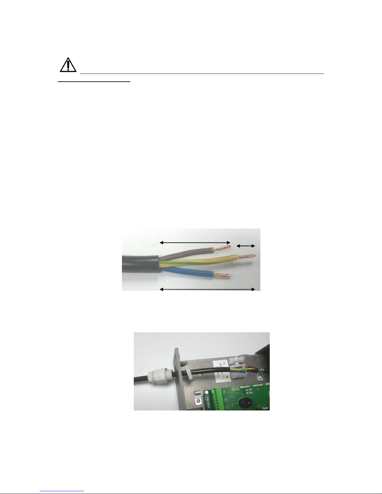
Please use the following procedure to prepare and connect the power supply cord:
1. Carefully strip the overall jacket and the individual wire insulation of flexible cord H05VV or
H07VV as shown on the picture below. The yellow/green wire shall be left abt 10 mm longer
than brown and blue:
2. Introduce power cord into cable gland on bottom on the panel and connect the stripped cord
wires to the terminal block as follows – brown to L, yellow/green to PE and blue to N:
8 mm
40 mm
30 mm
12
Sep 2018 – Version 3.1.5
FG-NET_Operation & Installation Manual_UK_v3.1.5_201809.docx
*For Europe, the mains cord shall meet the requirements of IEC 60227 or IEC 60245. For USA and
Canada, the mains cord shall meet the requirements of ANSI/UL 817 and CSA C22.2 No.21. For
other countries, please refer to relevant standard.
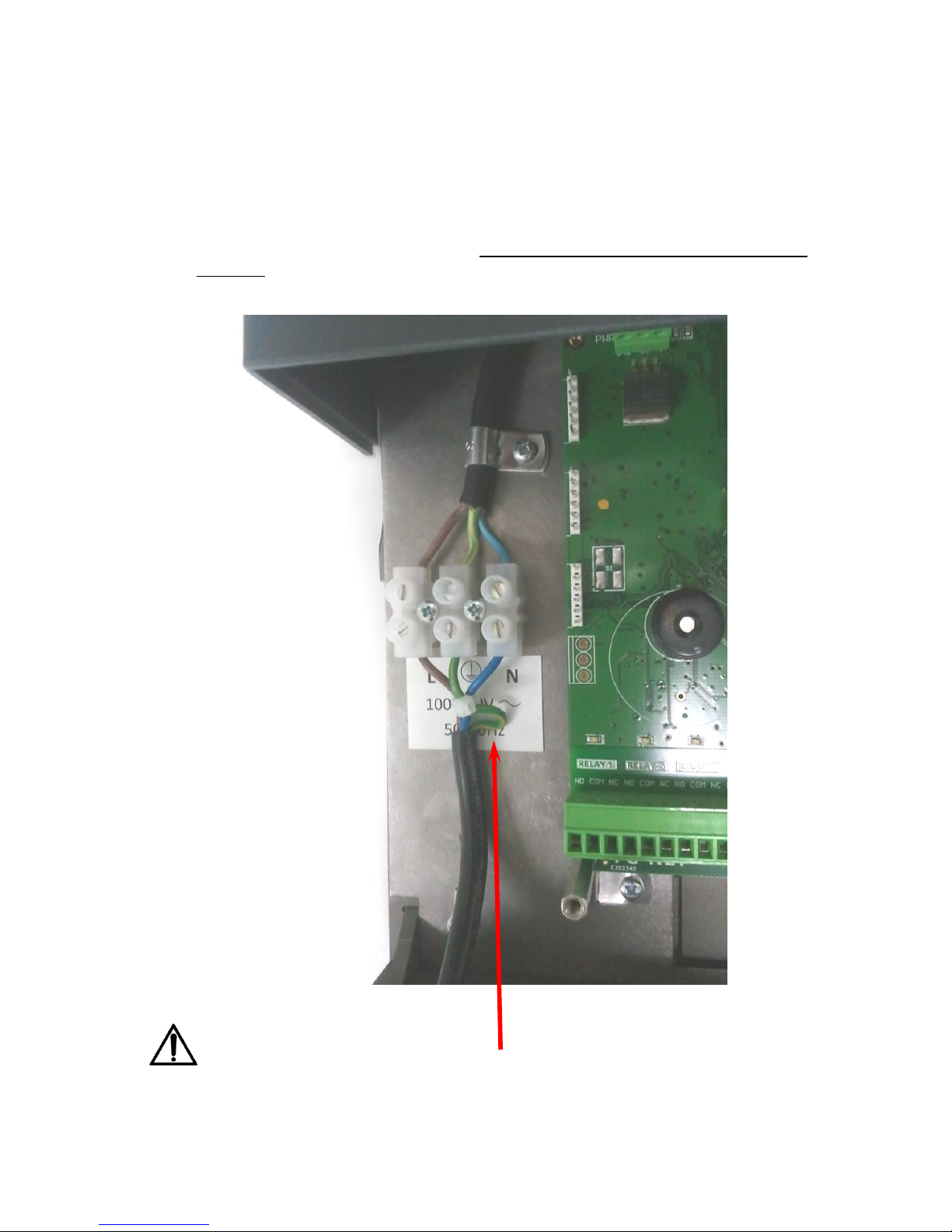
3. Fix tightly together the three wires of the power cord at the terminal block with the supplied
cable tie as shown on the picture. Cut the free length of the cable tie and fix the cable gland
on the panel bottom and on the cable – the power cord shall be slightly loose inside the
enclosure:
Please note the extra length of the grounding wire!
(See also Appendix n°1: FG-NET Digital Unit Electrical Connections)
13
Sep 2018 – Version 3.1.5
FG-NET_Operation & Installation Manual_UK_v3.1.5_201809.docx
When the unit is used in a way not specified by the manufacturer, the protection guaranteed by the
device can be compromised.
IF THE DEVICE IS PERMENANTLY IN USE an interrupter or circuit breaker must be used.
If there is no interrupter included with the unit:
- An interrupter or circuit breaker from the site‘s electrics should be put into use.
- It should be in close proximity to the unit and within easy access of the OPERATOR.
- It should be marked as the unit’s disconnecting and earthing device.
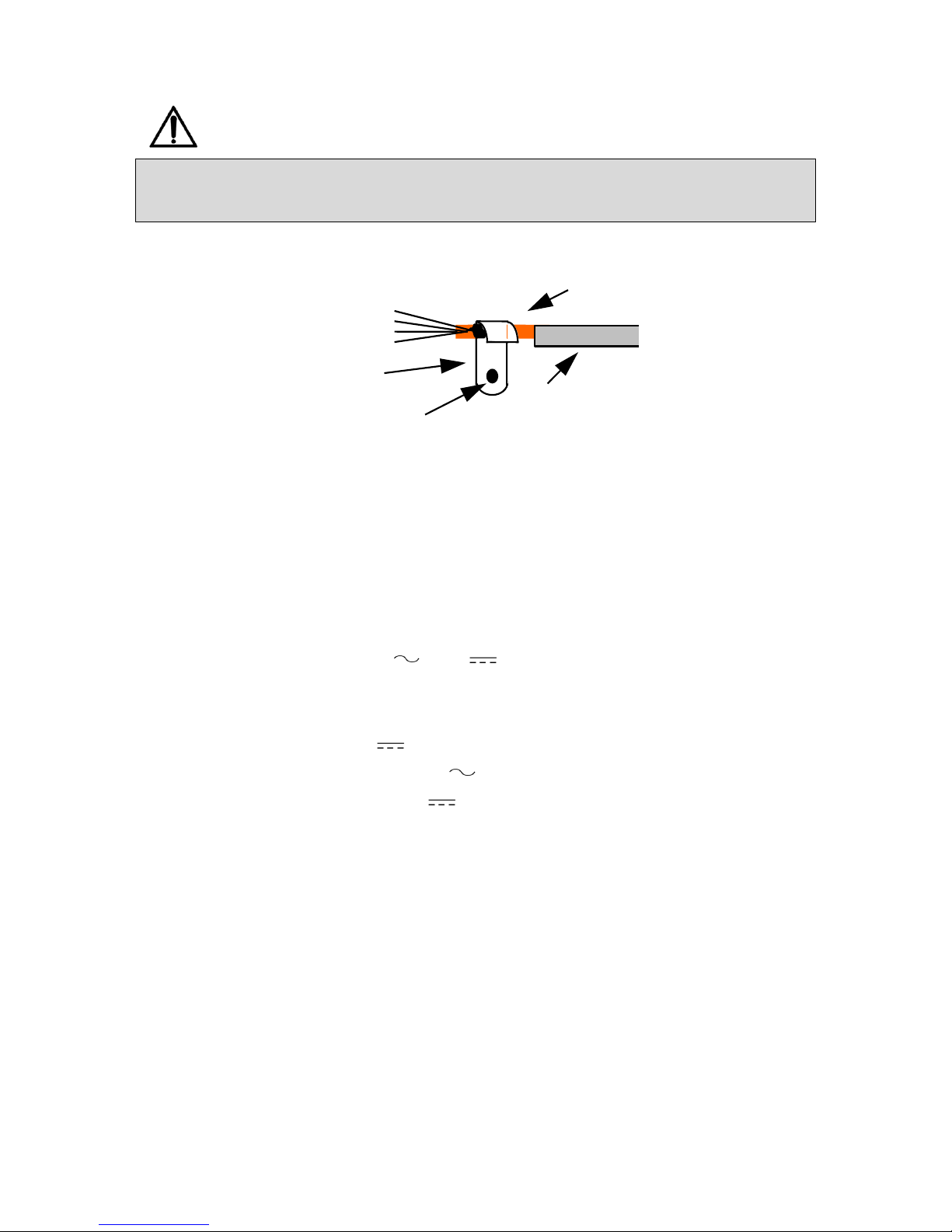
3.3. Connecting the leader cable FG-CLC
(See Appendix no. 1)
Each circuit of sense cables (1, 2 or 3) is connected to the FG-NET Digital Unit with a TTK leader cable
(Belden 8723), ref. FG-CLC
An inversion between the two couples red + black, and green + white can damage the electronics of
the first connected sense cable.
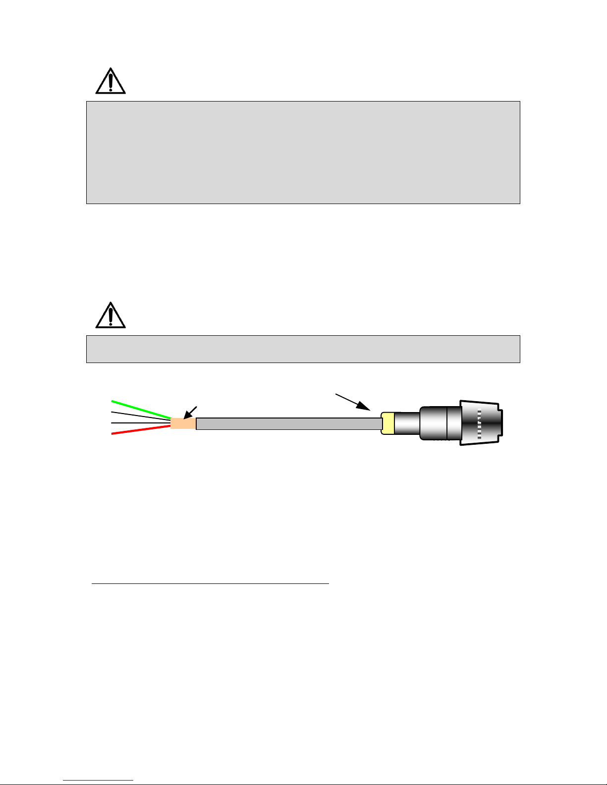
Female connector
Adhesive ring
Heat shrinkable tube
Green
Black
Red
White
C
L I P P E
R
Leader Belden 8723 Cable : FG-CLC
Shielding with copper adhesive
Three circuits are available; use circuit no.1 initially, then the following circuits (if necessary).
Each circuit has a maximum capacity of 40 sense cables.
When circuit no.2 is used:
• Remove the existing shunt between 2A and 2B.
When circuit no.3 is used:
• Remove the existing shunt between 3A and 3B.
14
Sep 2018 – Version 3.1.5
FG-NET_Operation & Installation Manual_UK_v3.1.5_201809.docx
To avoid electromagnetic disturbances and emissions (ECM), it is necessary to connect the shielding
of the leader cable to the earth. Fix the shielding of the leader cable using a metal cable clamp
(available inside the casing).
(See Appendix: Digital Unit Connection: FG-NET E / FG-NET F)
Metal cable clamp
Cable
Shielding
Insulation
Earth
screw
3.4. Connecting the internal relays
Nine internal relays are available on the FG-NET Digital Unit with connector blocks. The electric
characteristics of these relays are as follows:
Type: 1 RT
Max. Switching Voltage: 125 V / 30 V
Max. Switching Current: 2 A
Max. Switching Power: 62.5 VA / 60 W
Working load min.: 5 V / 1 mA
Nominal load: 0.5 A to 125 V
2 A to 30 V
You can configure each of the relays in the ‘CABLES’ MENU.
Relay configurations are as follows:
- Fault type: Leak or cable break, leak and cable break, OFF.
For each sense cable, the user can create a list of relays to be activated on leaks, or cablebreaks, or
both of them. It’s possible to use the internal relays, and/or external relays when using a FG-RELAYS
additional device providing up to 24 relays per box (max 16 boxes) for a total of 393 relays.

15
Sep 2018 – Version 3.1.5
FG-NET_Operation & Installation Manual_UK_v3.1.5_201809.docx
3.5. Connecting the serial cable
The serial cable is used as an exit towards a JBUS/MODBUS communication in RS232 or RS422/48. It
is connected to a SERIAL connector (see Appendix: Digital unit connection: FG-NET E / FG-NET F).
The 4-point connector is used for the RS422/485 and the 3-point connector for the RS232. Please
note that the simultaneous use of RS232 and RS422/485 is impossible.
3.6. Closing the FG-NET F Digital Unit
Once all connections have been finished, close the FG-NET F Digital Unit (as shown below):
For the rack version (FG-NET E), we recommend fixing the various cables carefully to the 19’ bay,
using a comb (for example).
16
Sep 2018 – Version 3.1.5
FG-NET_Operation & Installation Manual_UK_v3.1.5_201809.docx
CHAPTER II: CABLE AND ACCESSORIES
INSTALLATION
The FG-NET system is modular. All the sense cables and accessories are pre-terminated with both
male and female connectors. This makes the installation quick, easy, and safe.
We recommend drawing a precise map of all zones to be fitted with sense cables, ensuring that all
installation zones are clean and dry before installation.
1. INSTALLING ADDRESSABLE SENSE CABLES
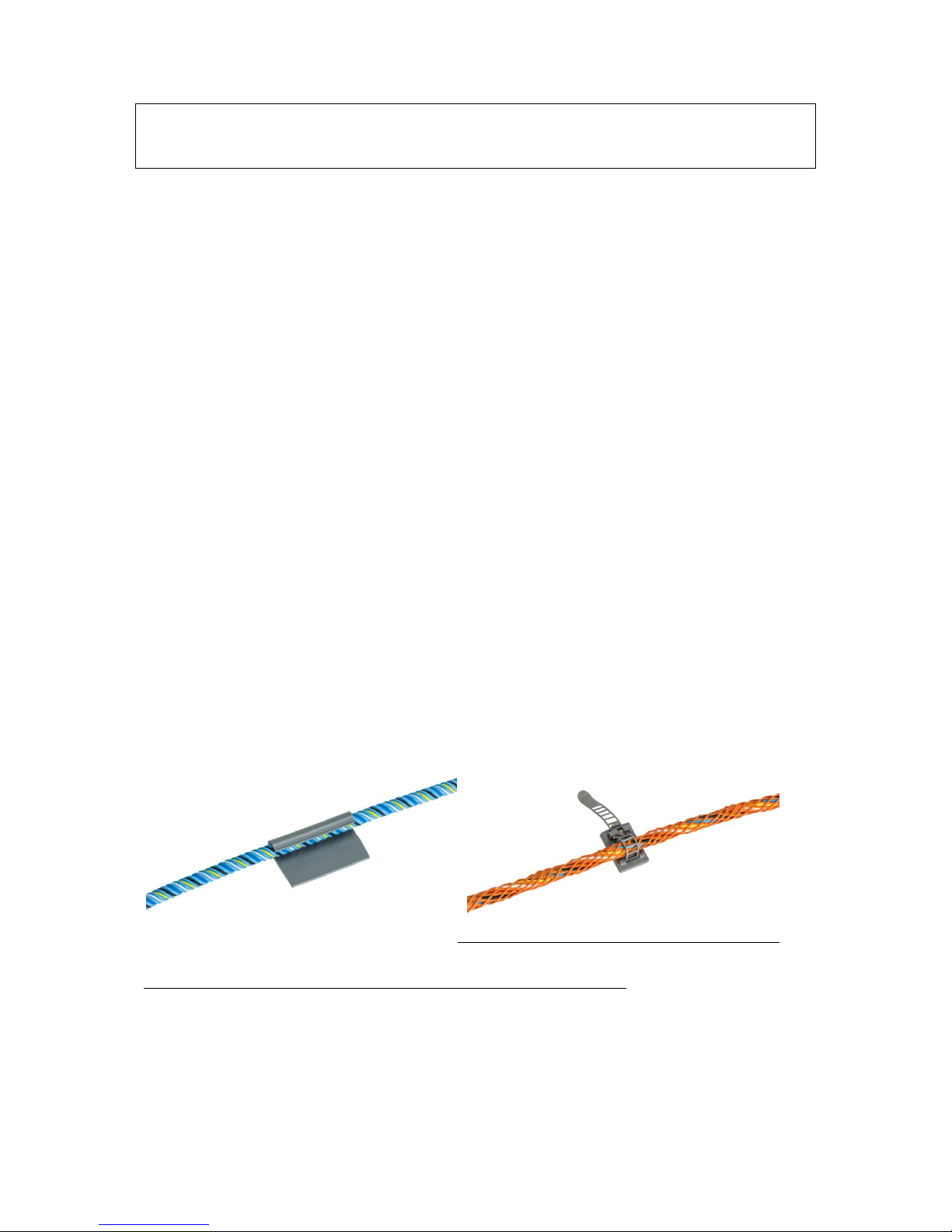
1.1. Hold-down adhesive clips
The sense cables are fixed to the earth with adhesive clips, type CF-EC100. (100 clips available per
tube of adhesive).
The first stage of the installation consists of sticking these clips to the earth using the adhesive
provided.
Recommendations:
1. To ensure the cable sticks correctly to the earth, alternate the direction of the clips on the earth.
2. The clips must follow the drawing of the sense cables and be spaced approximately 1 metre apart.
3. Wherever there is a curve of the trajectory, stick 1 clip the entry point and a second at the exit
point of curve.
4. Please wait for the clips to be completely dry (three to four hours), before installing the sense
cables.
5. When fixing the sense cables into the clips, keep a length of approximately 10 cm between the
connector and the clip.
Hold-down adhesive clips on a section of the sense cable (product ref. CF-EC100; CF-OD50)

17
Sep 2018 – Version 3.1.5
FG-NET_Operation & Installation Manual_UK_v3.1.5_201809.docx
1.2. Installing sense cables: FG-EC, FG-AC and FG-ECX
Unroll the entire length of the sense cable and place in the clips fixed on the floor before
installation.
Caution!
Pay attention to the direction of the sense cables!
The FG-CLC leader cable is connected to the FG-NET Digital Unit. The sense cable starts with a male
connector, and ends with a female connector. On board electronics are located at the end of the
sense cable.
1. Connect the first sense cable to the leader cable (coming from the FG-NET Digital Unit).
2. It is recommended that you avoid placing the cables in direct contact with the jacks (on the
raised floor), the cable trays, any other obstacles...
3. Take care to circumvent the air-conditioning system (at a distance of approximately 50 to 75
cm), to avoid false leak alarms related to harmless water projections.
4. All partitions must be fitted with pre-determined neutral Belden 8723 cables: type FG-NC (1
or 3 metres).
5. Once the sense cables are fixed with clips, their length must be maintained along the flooring
or ceiling in a closed retention tray, etc…
6. ES-40 tags must be placed along the length (packet of 40 tags) and spaced approximately
every 4 metres.
7. Place a new length of sense cable (a pre-terminated neutral Belden 8723 cable and finish the
circuit with a modular end termination plug.
1.3. Installing hydrocarbon and solvent sense cables: FG-OD
DESCRIPTION
The Oil&Gas FG-OD detection cable from TTK allows for the fast detection of any leaks of
hydrocarbon liquids. The presence of a real liquid leak, hydrocarbon or solvent, activates an audible
alarm, and detailed information is displayed on the Digital Unit with the hour, date, and type of fault:
leak or cable break. The dry contact related to the fault switches to the alarm position. This dry
contact makes it possible to drive an external alarm and be reported to a management team via
BMS, remote monitoring, solenoid valve, etc...
The dry contact remains activated as long as the alarm is present. Once the alarm has been cleared,
the relay returns to its initial position.
Due to ATEX regulations, FG-OD cables are using a different communication protocol, and they must
be connected to the system through a bus interface box FG-DOD. Up to 10x FG-OD cables can be
connected to one FG-DOD box.

18
Sep 2018 – Version 3.1.5
FG-NET_Operation & Installation Manual_UK_v3.1.5_201809.docx
The FG-OD kit contains:
1. A OD bus interface box for up to 10x FG-OD (FG-DOD)
2. A length of FG-OD sense cable (3, 7 or 12m)
3. A OD leader cable (FG-CLOD)
4. A OD end termination plug (FG-TMOD)
5. Hold-down adhesive clips (CF-OD50)
6. FG-OD kit installation instructions
Caution!
All FG-OD hydrocarbon or solvent sense cables must be installed in clean areas.
Connection with a FG-NET Digital Unit:
The set contains:
1. FG-NET Digital Unit
2. One or more Digital FG-OD kits for FG-NET (up to 40x FG-OD cables per circuit)
3. One or more additional FG-OD sense cables (max 10 FG-OD per FG-DOD)
To connect the FG-NET Digital Unit, follow the FG-NET installation instructions guide in chapter 1.3 of
this document.
FG-NET haves a capacity of 40x FG-OD cables per circuit. Those cables must be connected to the
panel through a FG-DOD bus interface by groups of ten cables maximum.
Example: 4x FG-DOD with 10x FG-OD cables each = 40x FG-OD
Or: 8x FG-DOD with 5x FG-OD cables each = 40x FG-OD
Or: 2x FG-DOD with 10x FG-OD cables each + 4x FG-DOD with 5x FG-OD cables each = 40x FG-OD
The FG-NET power supply must be switched off.
1. Connect the Belden 8723 cable to circuits 1, 2 or 3 in the FG-NET Digital Unit:
On circuit no.1:
Green wire: Point 1A
White wire: Point 1B
Black wire: Point 1C
Red wire: Point 1D
2. Connect the other end of the Belden jumper cable to the INPUT points of the first FG-DOD
interface box.
3. Take the FG-CLOD 3.5 m leader cable and connect it to the following points of the ‘OD BUS’
terminal of the first FG-DOD interface box:
White wire: Point B
Black wire: Point C
Red wire: Point D
19
Sep 2018 – Version 3.1.5
FG-NET_Operation & Installation Manual_UK_v3.1.5_201809.docx
4. Fix the provided hold-down clips (1 clip per meter) and place the FG-OD sense cable in the
clips.
5. Connect the FG-OD cable to the FG-CLOD leader cable, then add a second, third… FG-OD
cable (10x max) and put the FG-TMOD end plug at the end of the last FG-OD cable.
6. 7. Pour some light Naphta on the cable to simulate a leak alarm.
7. ‘OUTPUT ’ is reserved for the neutral cable going towards the next detection zones.
8. Proceed as with stage 2 for the second (and third etc.) FG-OD kits.
9. Note: on the last FG-DOD box, a bridge must be installed on the unused ‘OUTPUT ’ terminal
between points A and B.
OPERATION AND MAINTENANCE
The FG-OD sense cable is insensitive to the limited presence of conducting liquids (water, bases or
acids); FG-OD is also insensitive to any residual traces (lower than 35 ml) of non-conducting liquids
(hydrocarbons or solvents). The sense cable absorbs this limited presence of liquid and does not
react.
In the presence of a quantity (at least equal to 50 ml) of non-conducting liquids (hydrocarbons or
solvents), the FG-OD sense cable activates an alarm on the Digital Unit.
FG-OD cables are reusable after a limited contact with hydrocarbons. Immerse the cable in light
Naphta during 30 minutes, then remove and allow drying for few hours.
Caution!
All hydrocarbon sense cables must be installed in clean areas.
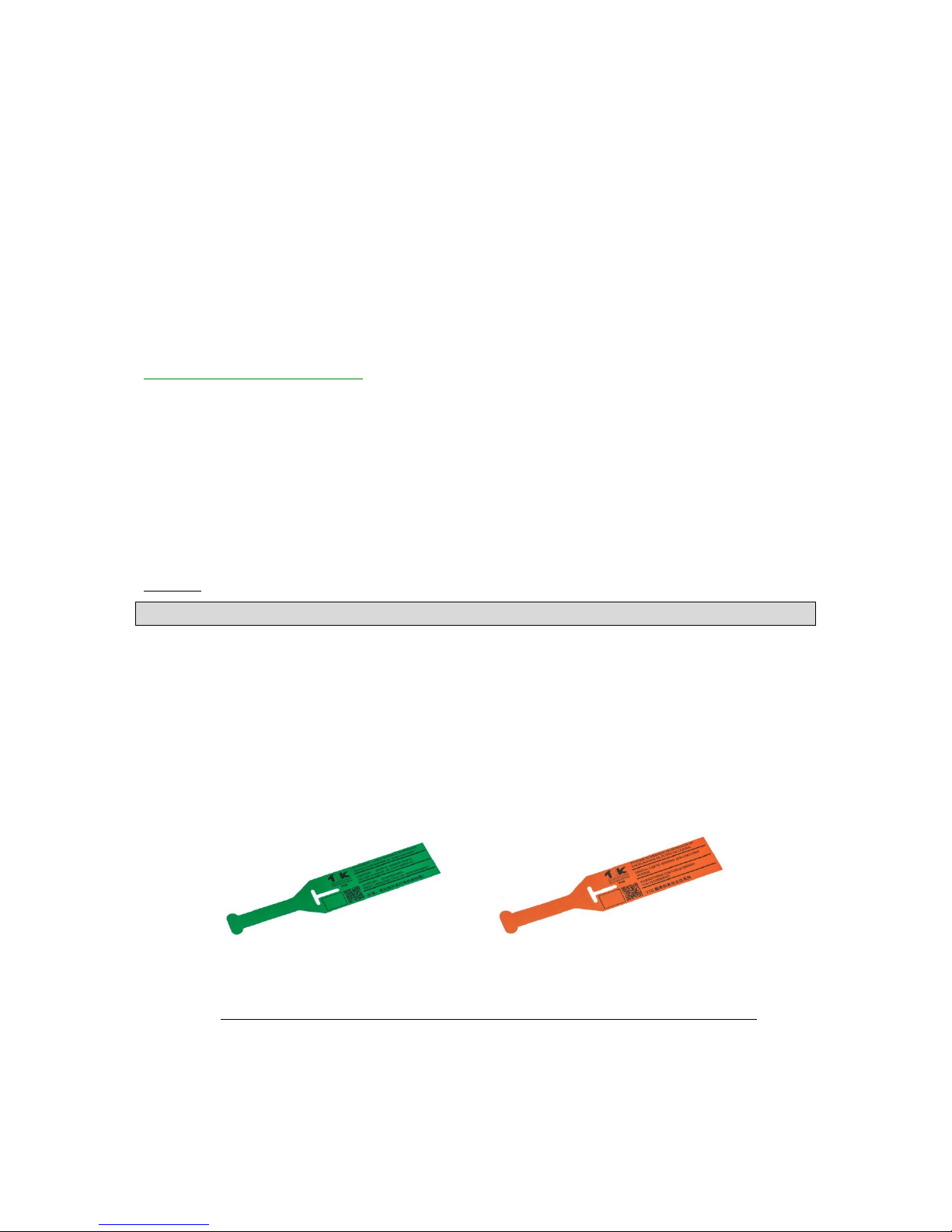
1.4. Labelling with tags
ES-EC and ES-OD tags indicate the presence of installed sense cables. Part of the label is intended for
the user to note the distances during water leak simulations.
• Fix the tags every five metres on the sense cable circuit.
• Ensure the tags are clearly visible.
Pack of 40 Tags, ref.: ES-EC (for water and acid sense cables); ES-OD (for oil sense cables)

20
Sep 2018 – Version 3.1.5
FG-NET_Operation & Installation Manual_UK_v3.1.5_201809.docx
2. INSTALLING FG-NC JUMPER CABLES
It can be necessary to use jumper cable to:
• Pass from one detection zone to another
• Connect the Digital Unit to the first detection zone
• Pass through any partitions...
Note:
To pass through partitions, the sense cable must be adapted with a product that suits any regulations
and / or the on-site architecture (partition wall, fireproofed walls etc.).
In order for the system to operate correctly, the following jumper cable should be used:
BELDEN 8723 (LSZH, if required)
This jumper cable must be equipped with a male and female connector in order to be compatible
with TTK sense cables. The FG-NC kit includes the following material for this purpose:
• A male CLIPPER with its 4 contacts
• A female CLIPPPER with its 4 contacts
• 2 heat-shrinkable sleeves (45 mm in retractable thermal heat gain (restraint: 24/6)
• 2 hot melt glue rings
• 1 jumper cable instructions
Tools required:
• Stripping pliers
• 800 w heat gun
• Flat-nose pliers
21
Sep 2018 – Version 3.1.5
FG-NET_Operation & Installation Manual_UK_v3.1.5_201809.docx
Jumper cable connection
The FG-CLC jumper cable is installed. The beginning of the jumper cable is at the end and coming
from the Digital Unit. Always start by making the connection at the beginning of the cable. The
beginning of each cable must be provided with a male connector and the end of the jumper cable
with a female connector.
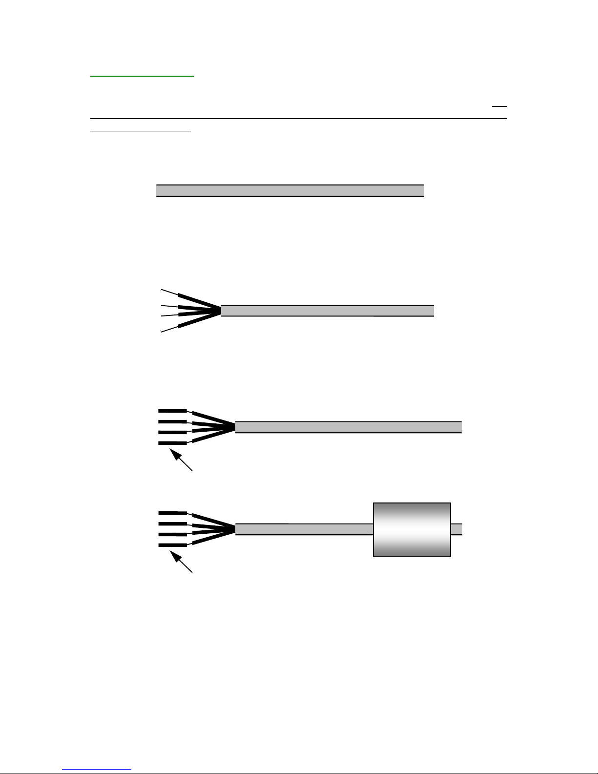
At the beginning of the Belden jumper cable: 8723 (8723LS):
Jumper cable BELDEN 8723
• Strip the external sheath by 20mm.
• Strip the 4 wires by 5mm.
• Do not cut the shielding wire.
Jumper cable: BELDEN 8723
• Crimp a male contact on each of the four wires. The shielding wire is to be crimped in the
same contact as the black wire.
Jumper cable: BELDEN 8723
4 Male Contacts
• Slide a 45 mm heat shrinkable tube onto the jumper cable.
Male contacts
45 mm heat shrinkable tube
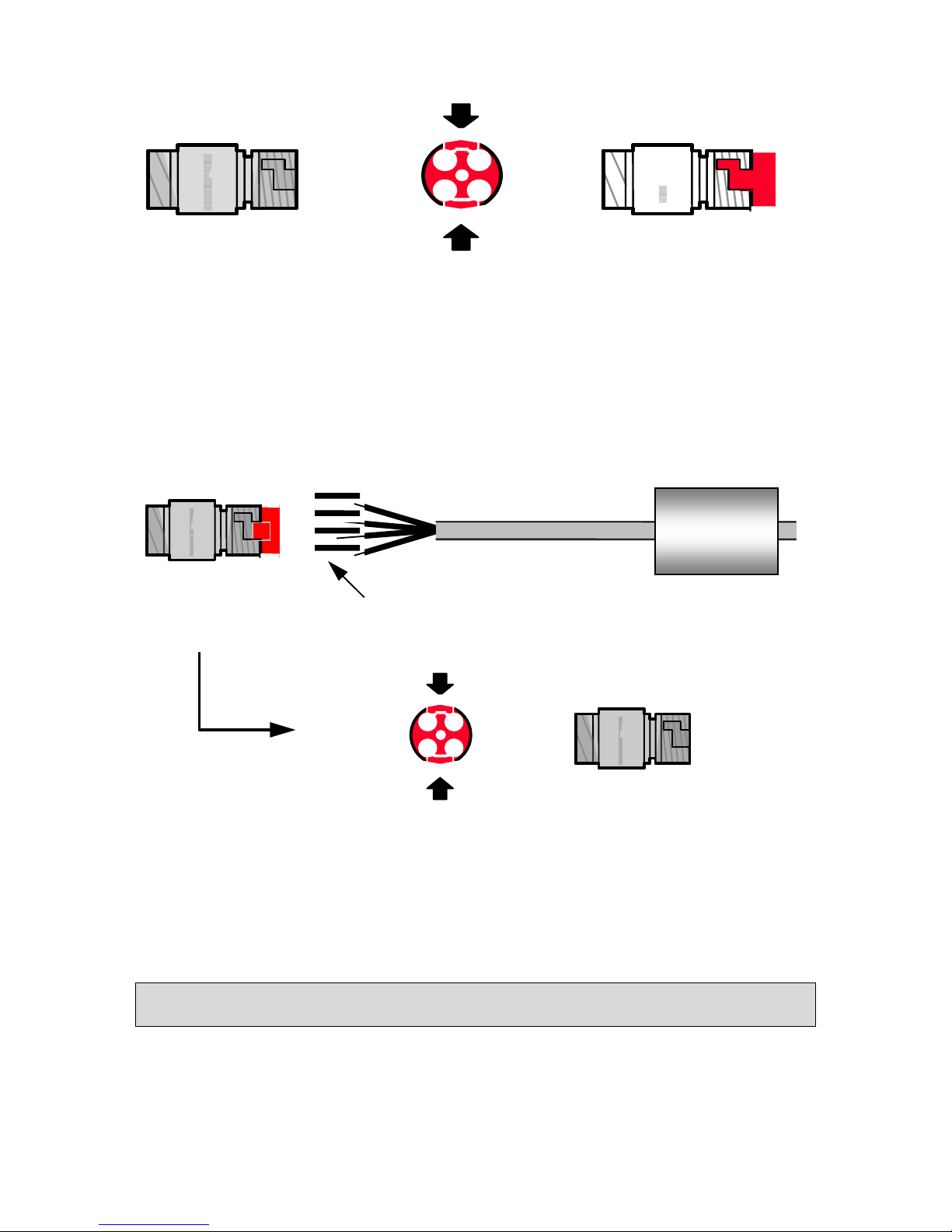
• Do not cut the shielding wire. Prepare the male connector (the longest).
• Encase the 4 contacts in the connector, pull the red plate while pressing on the sides (it
should not be entirely removed. This is normal).
22
Sep 2018 – Version 3.1.5
FG-NET_Operation & Installation Manual_UK_v3.1.5_201809.docx
Male connector
C
L I P
P E R
Press and pull
The red plate is
extended
C
L I P
P E R
1
4
3
2
Insert the four contacts then using the following code:
Red wire: point no.1 of Male Connector
Black wire + shielding: point no.2 of Male Connector
White wire: point no.3 of Male Connector
Green wire: point no.4 of Male Connector
And then, return the red plate to its original position by pressing on the sides.
4 Male contacts
45 mm heat shrinkable tube
1 2 3
4
Male connector
Insert the 4 contacts
C L I
P
P
E
R
The red plate is pushed in and
the contacts are blocked
Press and push
1
4
3
2
Green
White
Black
Red
C L I P P E R
The wires are now blocked.
This process makes it possible to easily remove at a later date if necessary.
Caution!
If the contacts are not entirely inserted into the connector, the red plate will not go back into the
connector.
23
Sep 2018 – Version 3.1.5
FG-NET_Operation & Installation Manual_UK_v3.1.5_201809.docx
Male connector
45 mm heat shrinkable tube
C L I
P P E
R
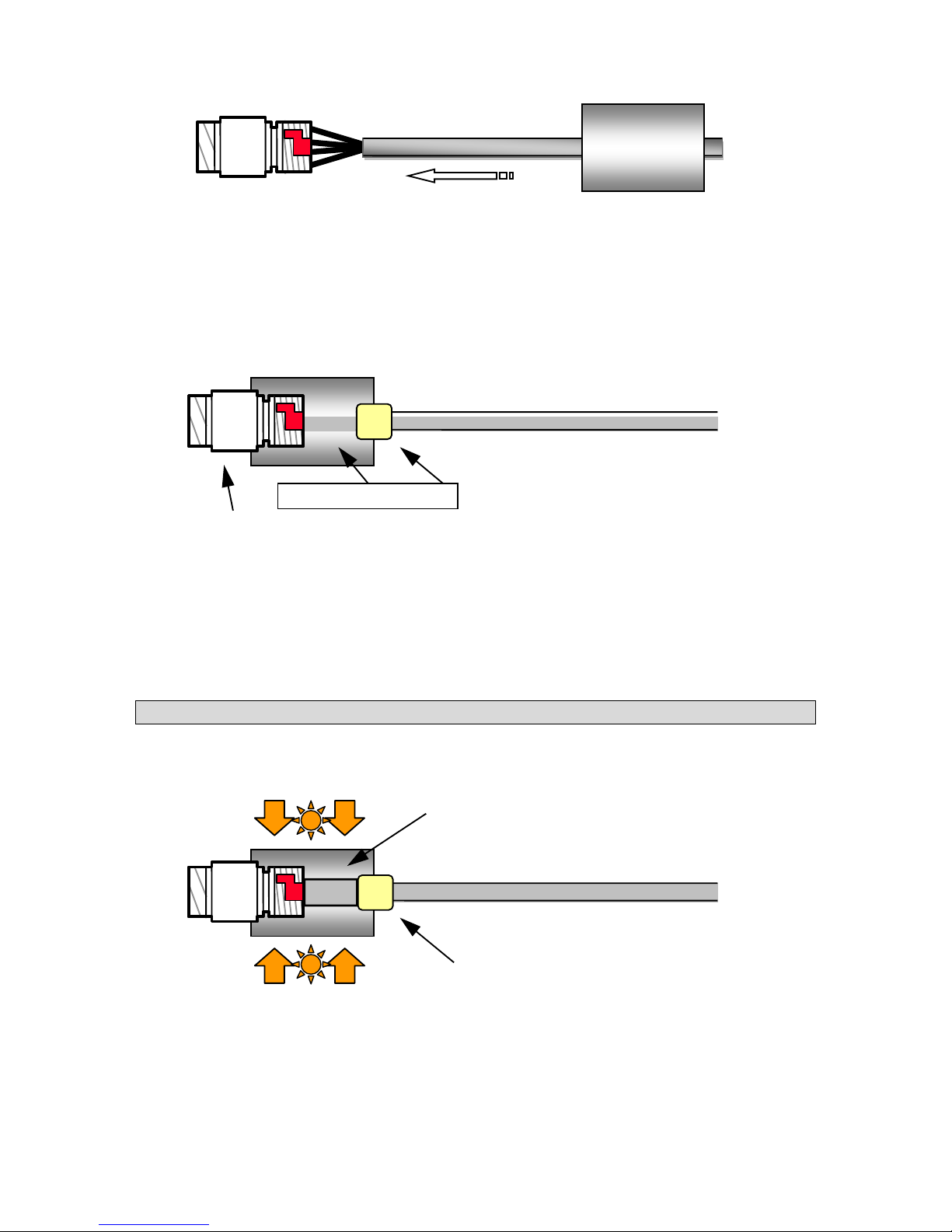
• Cover the connections and screw with the heat shrinkable tube (which should already have
been slipped onto the cable).
• Place an adhesive ring (a circle of glue) at the rear of the tube, on the cable side.
Adhesive ring
C
L I P P E
R
Jumper cable:BELDEN 8723
Male connector
45 mm heat shrinkable tube
• Heat the whole cable with a heat gun to shrink the tube. Heat it on the side of the male
connector whilst holding it down so that it remains in place. Then heat the whole of the
heat shrinkable tube.
• Heat it sufficiently to melt the adhesive ring until the adhesive is visible outside the tube (on
the cable side).
Caution!
Do not heat it too much, or you risk the cable overheating and melting.
Heat to shrink the tube
Adhesive ring
C L I P P
E
R
Jumper cable: BELDEN 8723
Heat shrinkable tube
Apply heat
24
Sep 2018 – Version 3.1.5
FG-NET_Operation & Installation Manual_UK_v3.1.5_201809.docx
Male connector
Jumper cable
Adhesive ring
Heat shrinkable
tube
C
L
I
P P E
R
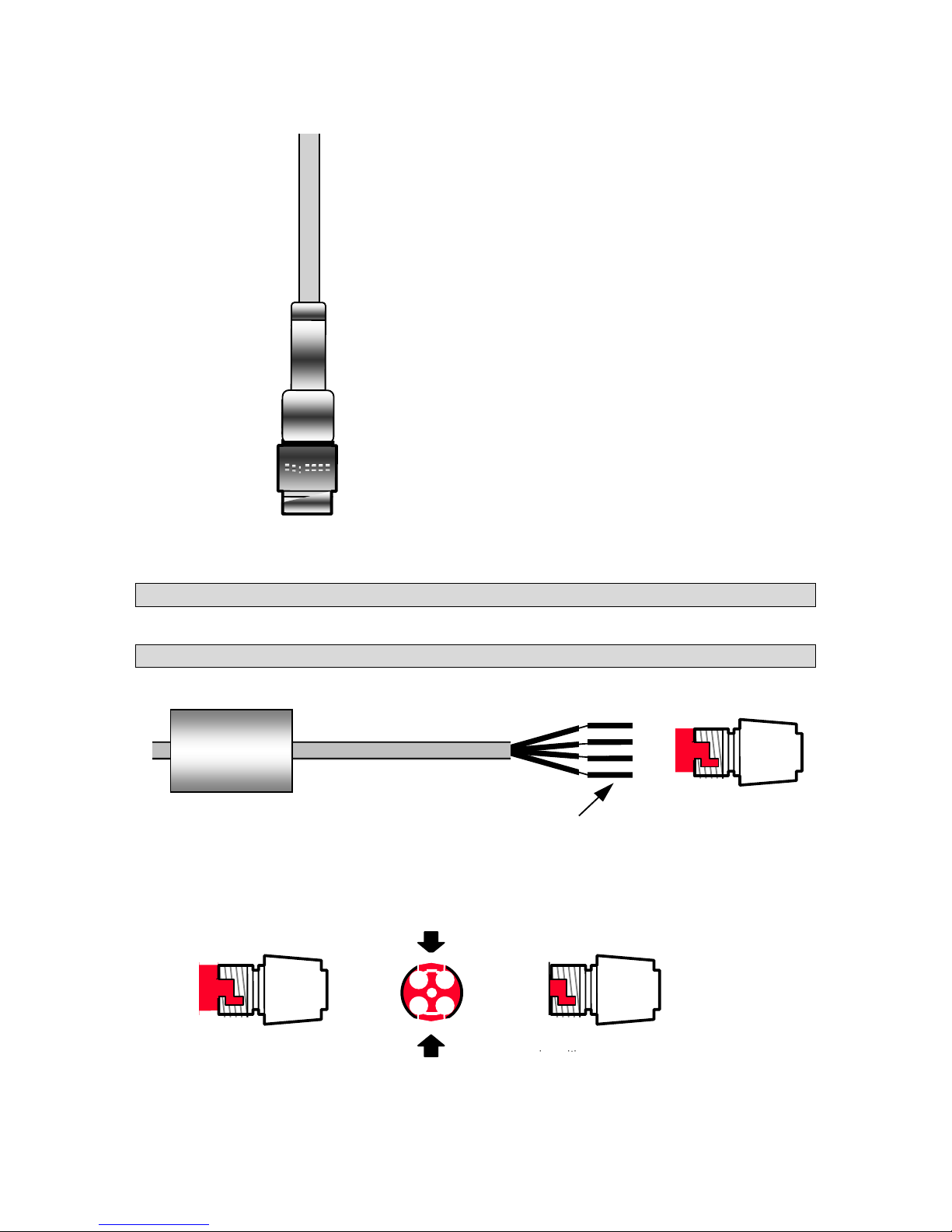
- Leave the tube cools down in a vertical position, with the connector facing downwards.
Proceed in the same way for the other end with a female connector and female contacts.
DO NOT CONNECT THE SHIELDING WIRE!
Female contacts
45 mm heat shrinkable tube
1
2 3 4
Green
White
Black
Red
Female connector
C L I P P
E
R
Female connector
Press and Pull
The red plate is back
Contacts are blocked
C L I
P P E R C L I
P P E
R
1
4
3
2
25
Sep 2018 – Version 3.1.5
FG-NET_Operation & Installation Manual_UK_v3.1.5_201809.docx
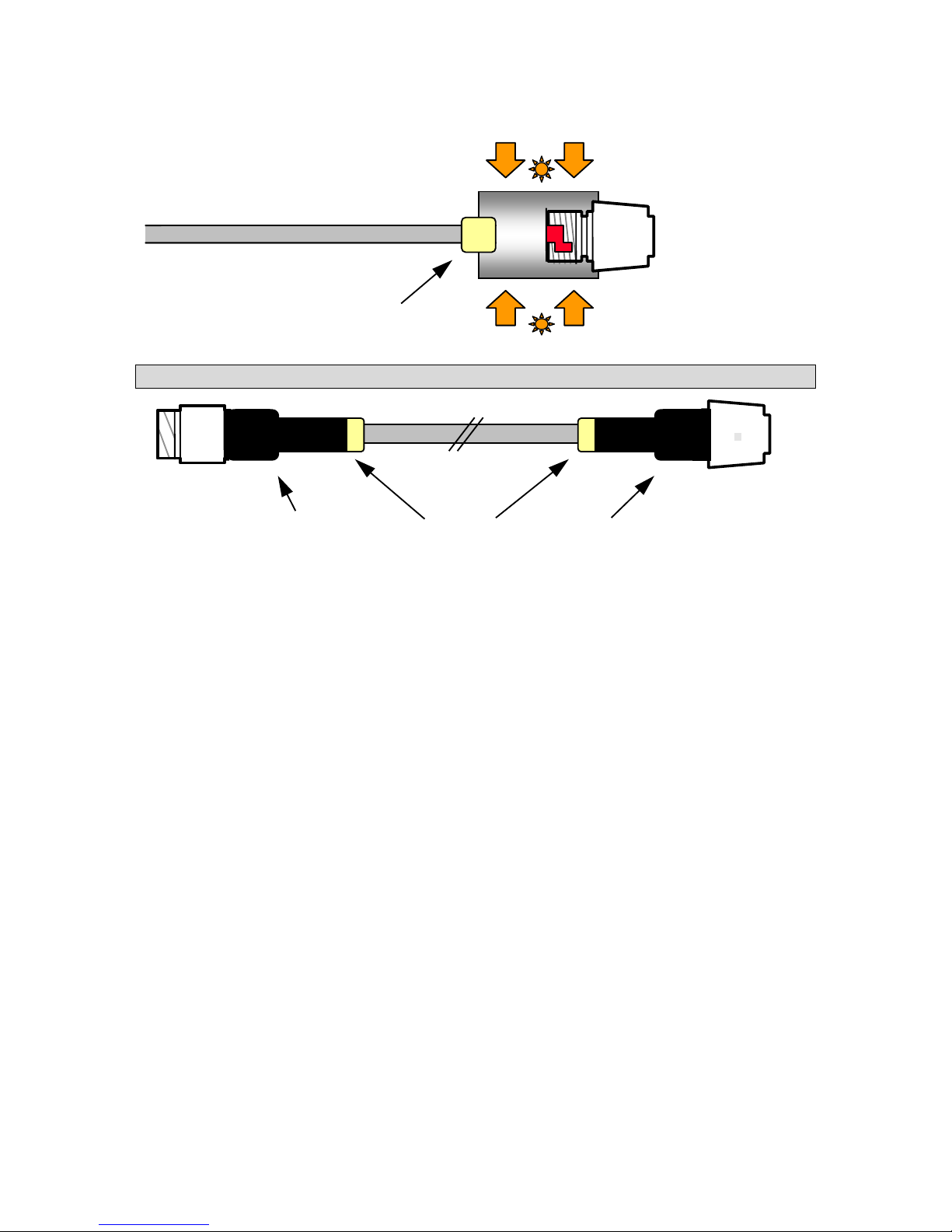
Heat to shrink tube
l
Adhesive ring
Jumper cable: BELDEN 8723
Apply heatr
C L I P P E R
The completed jumper cable is as follows:
Male connector
Female connector
Adhesive rings
Heat shrinkable tube
C L I
P P E
R
C L I
P P E
R
Heat shrinkable tube
BELDEN 8723
26
Sep 2018 – Version 3.1.5
FG-NET_Operation & Installation Manual_UK_v3.1.5_201809.docx
3. INSTALLING CONNECTION ACCESSORIES
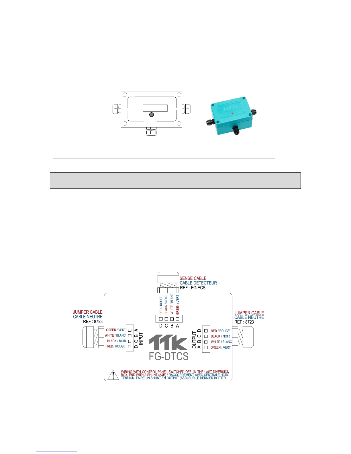
3.1. FG-DTCS - Addressable Box
The FG-DTCS addressable box allows the connection of the FG-ECS sense cable to the main bus wire;
this box is provided with three holes with cable glands: 'INPUT', 'OUTPUT' and 'FG-ECS '.
INPUT OUTPUT
LIQUID LEAK DETECTION SYSTEMS
TTK
Made in France
FG-DTCS
CE TUV LR
AMONT
AVAL
DERIVATION
SENSOR
The connection diagram is located on the addressable box packaging. (See below for details)
Caution!
In the last sector addressable box, the circuit must be completed with a shunt in the OUTPUT of the
circuit board (between A and B).
The INPUT is linked to the Belden cable coming from the FG-NET Digital Unit, or from the last FGDTCS addressable box
The OUTPUT is linked to the Belden cable leaving towards the next addressable box
The FG-ECS / FG-ACS exit is linked to the FG-ECS or FG-ACS sense cable.
The LED on the front face of the box indicates the box’s status in real time:
• Blinking green: normal, no alarm.
• Blinking red: leak detected on the box.
• No LED light: cable break detected on the box or loss of communication.

27
Sep 2018 – Version 3.1.5
FG-NET_Operation & Installation Manual_UK_v3.1.5_201809.docx
3.2. FG-DCTL – “Cut-to-Length” Addressable Box
The FG-DCTL “Cut-to-Length” addressable box allows the connection of custom lengths (from 1 to 45
meters) of FG-ECS, FG-ACS, FG-ECX and FG-ACX sense cable to the main bus wire; this box is provided
with three holes with cable glands: 'INPUT', 'OUTPUT' and 'SENSOR '.
INPUT OUTPUT
LIQUID LEAK DETECTION SYSTEMS
TTK
Made in France
DERIVATION
AVAL
FG-DCTL
AMONT
CE TUV LR
SENSOR
The connection diagram is located on the addressable box packaging. (See below for details)
Caution!
In the last FG-DCTL addressable box, the circuit must be completed with a shunt in the OUTPUT of
the circuit board (between A and B).
The INPUT is linked to the Belden cable coming from the FG-NET Digital Unit, or from the previous
FG-DCTL addressable box
The OUTPUT is linked to the Belden cable leaving towards the next FG-DCTL addressable box.
The SENSOR output is linked to the FG-ECS, FG-ACS, FG-ECX or FG-ACX sense cable.
Up to 30 FG-DCTL boxes can be installed on one circuit, with a maximum of 70 FG-DCTL boxes on one
panel.
The LED on the front face of the box indicates the box’s status in real time:
• Blinking green: normal, no alarm.
• Blinking red: leak detected on the box.
• No LED light: cable break detected on the box or loss of communication.
28
Sep 2018 – Version 3.1.5
FG-NET_Operation & Installation Manual_UK_v3.1.5_201809.docx
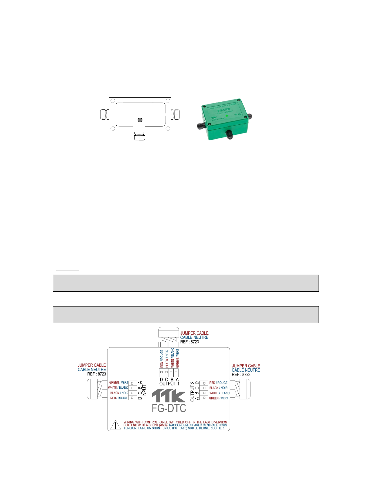
3.3. FG-DTC - TTK Bus Diversion
The TTK Bus Diversion box makes it possible to break up a detection circuit into two parts. The box is
provided with three cable glands: ‘INPUT’, ‘OUTPUT2’ and ‘‘OUTPUT1’.
Diagram:
INPUT OUTPUT 2
LIQUID LEAK DETECTION SYSTEMS
TTK
Made in France
AMONT
DERIVATION
AVAL
FG-DTC
CE TUV LR
OUTPUT 1
The connection diagram is located on the box packaging.
See below for instructions on how to connect the FG-EC or FG-AC cables to the main bus wire, or to
connect the sense cables to each other.
The INPUT is linked to the Belden cable coming from the FG-NET Digital Unit, or from the last FG-
DTCS diversion box
OUTPUT1 is linked to the FG-EC or FG-AC sense cables.
OUTPUT2 corresponds to the Belden cable at the end of the circuit.
The LED on the front face of the box indicates the box’s status in real time:
• Blinking short blue followed by a long green: normal, no alarm.
• Blinking short blue only: cable break detected on the box.
• No LED light: loss of communication.
Caution!
When an output is not being used (for example OUTPUT 2 in the last diversion box), a shunt is
needed between A and B.
Caution!
Installation of the FG-DTC diversion box must ONLY be performed when the FG-NET Digital Unit is
switched off.

29
Sep 2018 – Version 3.1.5
FG-NET_Operation & Installation Manual_UK_v3.1.5_201809.docx
3.4. FG-DOD - OD Bus Interface
The OD Bus Interface box makes it possible to integrate FG-OD cables on a standard TTK Bus
installation with water/acid sensors. The box is provided with three cable glands: ‘INPUT’, ‘OD BUS’
and ‘‘OUTPUT’.
Diagram:
INPUT OUTPUT
LIQUID LEAK DETECTION SYSTEMS
TTK
Made in France
AMONT
DERIVATION
AVAL
FG-OD
CE TUV LR
OD BUS
The connection diagram is located on the box packaging.
See below for instructions on how to connect the FG-OD cables to the main bus wire.
The INPUT is linked to the Belden cable coming from the FG-NET Digital Unit, or from a previous box
OD BUS is linked to the FG-OD sense cables (10 x max per FG-DOD box)
OUTPUT corresponds to the Belden cable towards the end of the circuit.
Caution!
When an output is not being used (for example OUTPUT on the last box), a shunt is needed between
A and B.
Caution!
Installation of the FG-DOD Interface box must ONLY be performed when the FG-NET Digital Unit is
switched off.
 Loading...