

THURLBY THANDAR INSTRUMENTS
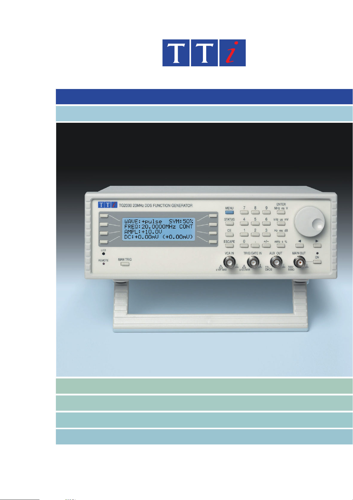
TG1000 & TG2000
10MHz & 20MHz DDS function generators
Sweep, AM, FSK & Tone switching modes
RS-232 and USB interfaces (TG2000 only)
Direct Digital Synthesis
A value-for-money 10MHz or 20MHz function generator
with the precision of Direct Digital Synthesis
A new price point
The TG1000/2000 breaks new groundby offering ahigh quality
DDS function generator at a significantly lower price.
DDS (direct digital synthesis) is a technique for generating
waveforms digitally usinga phaseaccumulator, a look-up table
and a DAC. The accuracy and stability of the resulting wave
forms is related to that of the crystal master clock.
When correctly engineered, the DDS generator offers not only
exceptional accuracy and stability but also high spectral purity,
low phase noise and excellent frequency agility.
Total digital control
Unlike some othergenerators whichonly provide digital control
of frequency, every function is digitally controlled enabling
complete instrument set-ups to be stored, or full remote control
to be implemented (TG2000 only).
Wide frequency and amplitude range
The TG2000 can generate waveforms between 0.001Hz and
20MHz with a resolution of six digits and a one year accuracy
better than 10ppm. The TG1000 has a 10MHz limit.
Amplitude is variable between 5mV and 20V pk-pk from a source
-
impedance of 50W or 600W.
Unlike many generators, the waveform quality remains excellent
over the full amplitude range.
RS-232 and USB interfaces
The TG2000 also includes both an RS-232 interface and USB
interface.
These interfaces can be used for remote control of all of the in
strument functions and for remotely storing instrument
set-ups.
-
u
0.001Hz to 10MHz or 20MHz frequency range, 6 digits or 1mHz setting resolution.
u
1ppm stability and better than 10 ppm absolute accuracy for one year.
u
Sine, square, triangle, positive pulse and negative pulse waveforms.
u
Low distortion, high spectral purity sine waves.
u
Internal sweep, linear or logarithmic, full range phase continuous, adjustable marker.
u
Modulations modes of gated, AM, FSK and tone switching; built-in trigger generator.
u
5mV to 20V pk-pk output from 50Wor 600W; plus multi function auxiliary output.
u
Storage for up to nine complete instrument set-ups in non-volatile memory.
u
Fully programmable via RS-232 or USB interfaces (TG2000 only).

and full digital control via RS-232 or USB (TG2000 only)
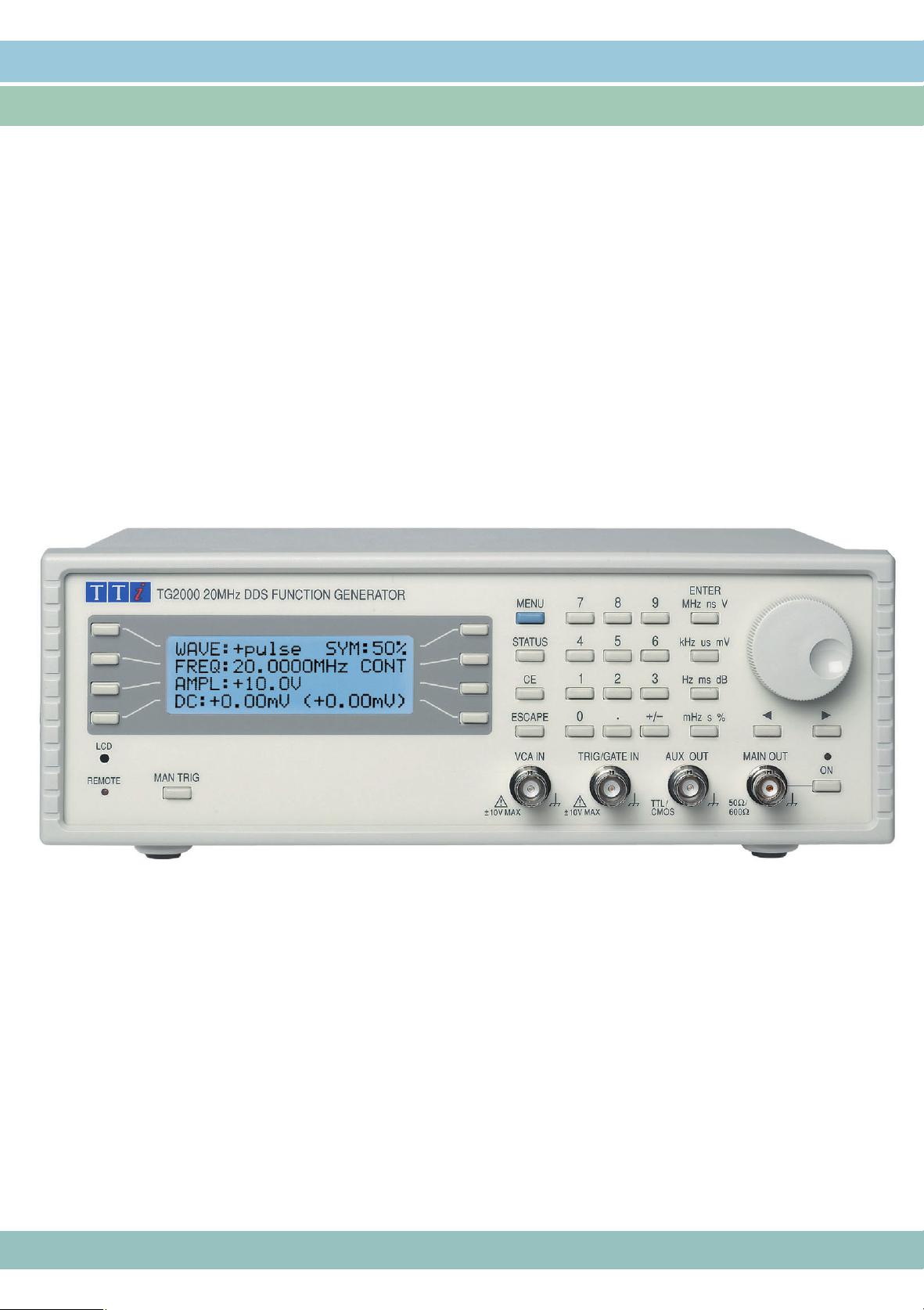
Ease of use
The TG1000 and TG2000 are particularly
easy to use. All of the main information is
clearly displayed on a backlit LCD with 4
rows of 20 characters. Sub menus are
used for the modulation modes and other
complex functions.
All parameters can be entered directly from
the numeric keypad. Alternatively most pa
rameters can be incremented or decre
mented using the rotary encoder for
quasi-analogue control.
Frequency or period entry
The generator frequency can be set in
terms of either frequency or period.
Numeric entry is floating point using what
ever units the operator prefers.
Flexible amplitude entry
Amplitudes can be enteredin termsof peak
to peak voltage, RMS voltage or dBm.
The output impedance can beset to 50W or
600W, and the amplitude can be set in
terms of either the voltage into the correct
termination, or the source EMF (for a high
impedance load).
Quick recall of settings
Both generators provide nine memories for
storing settings.
Because all parameters are controlled
electronically, the memories store the full
set-up of the instrument and automated
test sequences are easy to set up.
In addition to the nine user memories, the
current state of the instrument is saved at
switch off. The user can choose to have
this state restored at switch on, or choose a
pre-defined default set-up.
Synchronisation
The auxiliary output socket canprovide any
one of three different Sync. signals.
Waveform Sync isa 50% duty cycle square
wave at the frequency of themain output.
Sweep Sync. outputs a pulse at the start of
each sweep andcan also output a pulse at a
user defined marker frequency.
Trigger Out provides a replica of the trigger
signal which can be from the trigger input
socket, the internal trigger/gate generator,
the manual trigger key, or thebus interface.
Modulation modes
Sweep
All waveforms can be swept over their full
frequency range (0.2Hz minimum) at a rate
variable between 50 milliseconds and
more than 15 minutes. The sweep is fully
phase continuous.
Sweep can be linear or logarithmic, single
or continuous. Single sweeps can be trig
gered from the frontpanel, thetrigger input,
or the digital interfaces.
A sweep marker is provided that is adjust
able whilst sweep is running. The markers
can provide a visual indication of frequency
points on a ‘scope or chart recorder.
-
Gated
The Gated mode sets the output signal on
or off depending on the gatingsignal state.
The gating source can be the front panel
key, internal trigger generator, trigger input
socket, or bus interface signal.
AM
External Amplitude Modulation of up to
100% is available for all waveforms via the
VCA input.
FSK
Frequency Shift Keyingprovides phasecoherent switching between two selected frequencies at a rate defined by the source.
The switching source can bethe front panel
key, internal trigger generator, trigger input
socket, or bus interface signal.
Tone Switching
The generator can be set to switch be
tween a number of different frequencies in
response to a trigger signal.
Up to 16 frequencies can be defined.
See the difference !
Ultimately what matters in a function gener
ator is the quality of the output signal.
The TG1000/2000 maintains the TTi
reputation for high signal quality at all
frequencies and all levels.
The waveform capture opposite shows just
how much difference that can make !
The 'scope display opposite was captured
from two 5MHz square wave signals each at
60mV pk-pk level into 50
The upper waveform is from a widely avail
able competitive DDS generator.
The lower waveform is from a TG2000.
W
.
-
Phase continuous frequency sweep.
-
Amplitude modulation using an external sine
wave modulation source.
-
Frequency switching in FSK mode.
-
-

Technical Specifications
Specifications apply at 18°- 28°C after 1 hour warm-up, at maximum output into 50W.
FREQUENCY
All waveforms are derived from a crystal clock using Direct Digital Synthesis.
Frequency Range: 1mHz to 10MHz (TG1000) or 20MHz (TG2000)
Resolution: 6 digits or 1mHz
Accuracy: ±10ppm for 1 year, 18
Tempco.: Typically <1ppm/
o
C to 28oC; ±1mHz below 0.2Hz
o
C outside of 18oC to 28oC
WAVEFORMS
Sinewave
Range: 1mHz to 10MHz/20MHz
Resolution: 6 digits or 1mHz
Distortion: <0.3% THD to 20kHz (typically 0.1%), <-45dBc to
Spurii: Non harmonically related spurii <-55dBc to 1MHz,
Output Level:
300kHz, <-35dBc to 20MHz (typically <-40dBc)
<(-55dBc + 6dB/octave) 1MHz to 20MHz
5mV to 20V pk-pk from 50W or 600W
Squarewave
Range: 1mHz to 10MHz/20MHz
Resolution: 6 digits or 1mHz
Symmetry: variable 20% to 80% in 1% steps
Aberrations: <5% + 2mV
Rise & Fall Times: <22ns
Output Level:
5mV to 20V pk-pk from 50W or 600W
Triangle
Range: 1mHz to 1MHz
Resolution: 6 digits or 1mHz
Linearity error: <0.5% to 100kHz
Output Level:
5mV to 20V pk-pk from 50W or 600W
Positive and Negative Pulse
Range: 1mHz to 10MHz/20MHz
Resolution: 6 digits or 1mHz
Symmetry: variable 20% to 80% in 1% steps
Aberrations: <5% + 2mV
Rise & Fall Times: <22ns
Output Level:
2.5mV to 10V pk-pk from 50/600W positive or negative
only pulses with respect to the DC Offset baseline
MODULATION MODES
Continuous
Continuous cycles of the selected waveform are output at the selected frequency.
Gated
Non phase-coherent signal keying - output is On while Gate signal is high and Off
while low.
Carrier frequency: From 0.1Hz to 10MHz/20MHz
Carrier waveforms: All
Trigger rep. rate: dc to 100kHz external, dc to 5kHz internal
Gate source: Front panel MAN TRIG key, Internal Gate Generator,
Sweep
Carrier waveforms: All
Sweep Mode: Linear or logarithmic, single or continuous
Sweep Width: 0.2Hz to 10MHz/20MHz in one range. Phase continuous.
Sweep Time: 50ms to 999s (3 digit resolution)
Markers: Available from AUX output. Variable during sweep
Sweep Trigger
source:
Amplitude Modulation
Carrier frequency: 1mHz to 10MHz/20MHz
Carrier waveforms: All
Modulation source: VCA IN socket
Frequency Shift Keying (FSK)
Phase coherent switching between two selected frequencies at a rate defined by the
switching signal source.
Carrier frequency: 1Hz to 10MHz/20MHz
Carrier waveforms: All
Switch rate: dc to 5kHz (internal), dc to 1MHz (external)
Switching signal
source:
TRIG/GATE input, or Remote Interface
Independent setting of the start and stop frequency
The sweep may be free run or triggered from: front panel
MAN TRIG key, TRIG/GATE input, or Remote Interface
Front panel MAN TRIG key, Internal Trigger Generator,
TRIG/GATE input, or Remote Interface
Tone
The tone is output while the trigger signal is high, and stopped when the trigger signal
is low. The next tone is output when the trigger signal goes high again.
Carrier waveforms: All
Frequency list: Up to 16 frequencies between 1Hz and 10MHz/20MHz
Min. switching time: 1ms per tone
Switching source: Front panel MAN TRIG key, Internal Trigger Generator,
TRIG/GATE input, or Remote Interface
Internal Trigger/Gate Generator
Period: 0.2ms to 999s (resolution 0.2 ms)
Waveform: Square wave (1:1 duty cycle)
MAIN OUTPUT
Output Impedance:
Amplitude:
Output can be specified as V-HiZ (open circuit value) or V (potential difference) in
pk-pk, RMS or dBm. Note that in positive or negative Pulse modes the amplitude range
is 2.5mV to 10V pk-pk O/C.
Accuracy:
Flatness: ±0.2dB to 500kHz; ±1dB to 10MHz; ±2dB to 20MHz
DC Offset:
Resolution: 3 digits for both amplitude and offset
50W or 600W switchable
5mV to 20V pk-pk open circuit (2.5mV to10V into 50/600W)
±3% ±1mV at 1kHz into 50W/600W
±10V from 50W/600W. DC offset plus signal peak limited to
±10V. Accuracy ±3% ±10mV
AUXILIARY OUTPUT
Multi-function output user definable to be any of the following:
Waveform Sync: Outputs a 50% duty cycle squarewave at the main wave
Trigger Out: Outputs a replica of the current trigger signal
Sweep Sync: Outputs a trigger signal at the start of sweep (for synchro
Signal Levels:
form frequency
nising an oscilloscope or chart recorder). Can additionally
output a sweep marker.
Output Impedance 50W nominal. Logic levels of <0.8V and
>3V. Sweep Sync is a 3 level waveform, low at start of
sweep, high at end of sweep, with a narrow 1V pulse at the
marker point
-
-
INPUTS
Ext Trig/Gate
Frequency Range: DC to 1MHz for FSK; DC to 100kHz for Gate; DC to 2.5kHz
Signal Range:
Min. Pulse Width: 100ns for Gate/FSK; 0.2ms for Sweep and Tone
Input Impedance:
for Tone and Sweep
Nominal TTL level threshold; maximum input ±10V
Typically 10kW
VCA In
Frequency Range: DC - 100kHz
Signal Range: 2.5V for 100% level change at maximum output
Input Impedance:
Typically 6kW
INTERFACES (TG2000 only)
Full remote control facilities are available through the RS232 or USB interfaces.
RS232: Variable Baud rate (19200 max), 9-pin D-connector. As
USB: Standard USB hardware connection. Conforming USB 1.1
well as operating in a conventional RS-232 mode the inter
face can be operated in addressable mode whereby up to
32 instruments can be addressed from one RS-232 port
-
GENERAL
Display: 20 character x 4 row alphanumeric LCD
Data Entry: Keyboard selection of mode, waveform etc.; value entry di
Stored Settings: Up to 9 complete instrument set-ups may be stored in
Size & Weight: 260(W) x 88(H) x 235(D) mm; 2kg (4.5lb)
Power: 100V, 110-120V or 220-240V ±10% 50/60Hz, adjustable in
Operating Range: +5
Storage Range: -20
Environmental: Indoor use at altitudes up to 2000m, Pollution Degree 2
Safety & EMC: Complies with EN6010-1 and EN61326
Thurlby Thandar Instruments Ltd. operates a policy of continuous development and re
serves the right to alter specifications without prior notice.
rect by numeric keys or by rotary control.
battery-backed memory.
ternally. 40VA max. Installation Category II.
o
C to 40oC, 20-80% RH
o
C to +60oC
-
-
-
Designed and built in Europe by:
Thurlby Thandar Instruments Ltd.
Glebe Road, Huntingdon. Cambs. PE29 7DR United Kingdom (UK)
Tel: +44 (0)1480 412451 Fax: +44 (0)1480 450409
Email: sales@tti -test.com Web: www.t t i -test.com
82100-1240 Issue 2
 Loading...