

Page 1
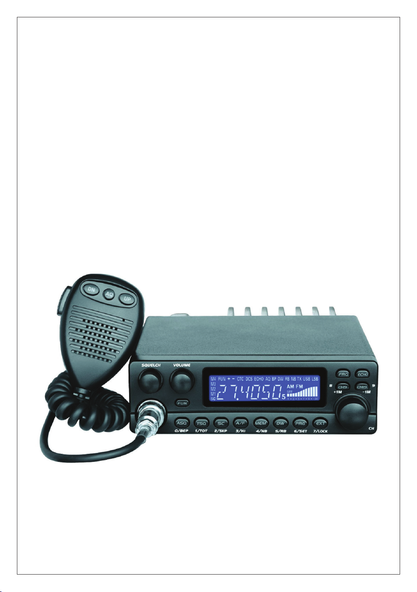
TTi TCB-5289
User manual / Manual de usuario / Használati utasítás
Manuale dell’utente / Instrukcja obsługi / Manual de utilizare
Page 2
WARNINGS
Please read the following precautions to prevent re, personal injury or the radio destruction.
Do not attempt to adjust the radio while driving; is dangerous.
This radio is designed for power supply at 13.8V DC. Do not use a 24V battery to power the radio.
Do not place the station on an excessively dusty, damp or unstable surface.
Do not connect the antenna during transmission, risk of burning or electric shock.
Please keep distance from devices that cause interference (such as TV, generator, etc.)
People who use pacemakers are advised to keep distance from the antenna during transmission and
especially not to touch it.
Do not connect metal objects to the internal electrical side; danger of electric shock.
Avoid exposing the radio to temperatures below -30°C and above + 60°C, the temperature on a vehicle
may sometimes exceed 80°C, which can cause irreparable damage to electric devices. Do not expose the
radio to sunlight.
Do not place anything on the radio, it will prevent it from cooling down.
Check to see if you have enough charged battery to avoid rapid discharge.
It is important to stop the radio before starting the engine, to avoid damage caused by high starting voltage.
You must use a 2A 250V fuse type F. Under no circumstances use a higher value.
If an abnormal odor or smoke is detected as coming from the radio, switch o the appliance immediately.
Do not transmit for a long time, the radio may warm up.
Keep the station away from children.
OTHER WARNING:
Before connecting or using this product, please read these operating instructions carefully. Keep this manual
for future reference.
Before using the radio, please connect the antenna, then check the SWR before transmitting. A too high SWR
can cause demage to the CB nal output transistors, which is not covered by the warranty.
The radio does not includes components that can be repaired by the user. Please contact an authorized
service center.
To prevent the risk of re, use only a suitable power supply.
INSTALL THE CB RADIO
• For installation, choose a location as simple and practical as possible.
• The radio station should not disturb the driver or passengers.
• The power and antenna cables should not disturb the driver while driving.
• To install the radio, use the holder and the self-adhesive screws included in the package (4 mm diameter
of drilling). Be careful not to damage the car’s electrical system when drilling the dashboard.
• Do not forget to insert the rubber joints between the radio and its support as these have a shock-absorbing
eect which permits gentle orientation and tightening of the set.
• Choose where to place the microphone support and remember that the microphone cord must stretch to
the driver without interferingwith the controls of the vehicle.
• If you install the radio in-board, to improve the sound quality, we recommend installing an external speaker
(the EXT SP connector on the rear panel)
ANTENNA INSTALLATION
• When choosing an antenna, keep in mind that the longer the antenna, the better its results
• Mount the antenna on the dome of the vehicle, on a metal surface
• If you already have a radio antenna installed, the CB antenna must be higher than this one
• There are two types of antennas: the pre-calibrated ones that should be installed on a surface with a good
ground plane and the adjustable ones that cover a larger frequency range and which can be installed on
a smaller ground plane.
2
Page 3

• For antennas that are xed by drilling, you need a good contact between the antenna and the table plane.
EN
To get this done, you should lightly scratch the surface on which the screw and nut are tightened.
• Be careful not to pinch or atten the coax cable to avoid the risk of permanent or short-circuit hazards.
• Connect the antenna to the station after it has been placed in the nal position.
• A xed antenna should be installed on as large an area as possible.
POWER CONNECTION
This is protected against an inversion of polarities. However, before switching it on, you are advised to check
all the connections. Your equipment must be supplied with a continued current of 12 volts (A). Today, most cars
and lorries are negative earth. You can check this by making sure that the negative terminal of the battery is
connected either to the engine block or to the chassis.
WARNING: Lorries generally have two batteries to supply a voltage of 24 volts, in which case it will be
necessary to insert a 24/12 volt converter into the electrical circuit. The following connection steps should be
carried out with the power cable disconnected from the set.
To power the radio, follow the steps below:
• Check if the battery has a voltage of 12 V
• Identify the positive and negative terminals of the battery (+ is red, - is black). If it is necessary to extend
the power cord, please use the same type of cable or a superior type of cable.
• It is necessary to connect your radio to a permanent (+) and (-). We advise you to connect the power
cable directly to the battery (as the connection of the cable to the wiring of the car-radio or other parts of
the electrical circuit may, in some cases, increase the possibilities of interference).
• Connect the red wire (+) to the positive end of the battery and the black wire (-) to the negative terminal.
• Connect the power cord to the radio station
WARNING: Never replace the original fuse (5A) by one of dierent value.
BASIC OPERATIONS
1. Connect the microphone
2. Check the antenna connections
3. Turn the set on by turning the volume knob clockwise
4. Turn the squelch knob to minimum(Full-anti clockwise)
5. Adjust the volume to a comfortable level
6. Go to channel 22 EC by using the channel knob
ADJUSTMENT OF SWR (STANDING WAVE RATIO)
WARNING: This must be carried out when you use your radio for the rst time (and whenever you re-position
your antenna). The adjustment must be carried out in an obstacle-free area.
• Connect the SWR meter between the antenna and the CB radio, as close as possible to the radio (use
a maximum 40 cm cable)
• Set the radio to 20 @ EC FM channel
• Place the button on the SWR meter on the CAL or FWD position
• Press the PTT key on the microphone to emit
• Bring index index to position ▼ using the calibration key
• Change the switch to the SWR (SWR level) position. The value of the SWR must be as close as possible
to 1. If you do not, adjust the antenna until you get a value as close to 1. A value between 1 and 1.8 is
acceptable.
• It is necessary to re-calibrate the SWR meter after each antenna setting
• The station is now ready to be used
3
Page 4

PRODUCT DESCRIPTION
1 2
SQUELCH
VOLUME
FU N
ASQ T SQ SC
/
/
BE P
O
3
/
1
2
SK P
TOT
4 5 6 7 8 9
INSTRUCTIONS FOR USE
14
15
EC HO
FR Q
CH9
CH 19
8
M
+
1
A /F
MEM
DW PRG EXT
/
/
HI
4
3
NB
/
/
6
SE T
5
RB
LOC K
7
/
10 11
12 13
9
M
-
1
CH
16
17
Front panel
B
ANT
EXT SP
19
18
DATA
Rear panel Microphone
1. Manual Squelch
Turn the SQUELCH knob clockwise to the exact point where all background noise disappears. Please note
that this control is ne regulation, if you set it to the maximum (fully clockwise), the radio can only receive the
strongest signal.
2. Volume switch
a. To turn the radio on, turn the VOLUME knob clockwise
b. To increase the sound level, turn the knob further clockwise.
3. FUN key (Functions)
a. Choose band
Press and hold it for over 2 seconds to enter band selection, turn the channel knob to choose a band, press
FUN again to exit, the radio will work on selected band.
The frequency and channel information in band A to band L, VFO (1 channel), MEM (8 channels) total 12
bands can be programmed by software. The frequency in band E, UK, PL can not be programmed, but the
channel information can be changed by software. Factory Defaulted with only E, UK band, add other bands by
software if need. Pay attention to the local laws.
b. Combined Functions
Press FUN, the LCD display “FUNC”, when “FUNC” disappear, press ASQ, TST, SC, A/F, MEM, DW, PRG key
to enter the function printed below the buttons.
4. Tasta ASQ
a. ASQ: Press ASQ, The LCD displays “ASQ”, the ASQ function is on; press it again to turn o ASQ.
4
Page 5

Note: ASQ will automatically turn o if the TSQ function turned on
EN
b. BEP: Press FUN, the LCD display “FUNC”, when “FUNC” disappear, press ASQ, the LCD displays “BP”, the
key beep function is on, press it again to turn o BEP function.
5. TSQ key
a. TSQ: CTCSS and DCS code
Press TSQ, The LCD will display “CTC or DCS”, the CTCSS or DCS function is on; press it again to turn o
the function.
Note1: This function is available only when you installed optional CTC board.
Note2: when you choose RXC or TXC o, this function is not valid.
Note3: When the CTCSS or DCS is on, the speaker will boot only when it receive corresponding CTCSS or
DCS code.
Note4: When the CTCSS or DCS is on, the RB function will turn o.
b. TOT (Timer Out Timer)
Press FUN, the LCD displays “FUNC”, when “FUNC” disappear, press TSQ, the LCD displays “XXX S”, you
can adjust the TX limit time by the channel knob, press any other key to exit, or wait for 5 seconds , the radio
will store the setup and exit.
When the continuous TX time is over the TOT limit, the radio will stop TX.
TOT Optional: 15-600 seconds, step 15seconds, default: 180 seconds
6. SC key
SC (Scan function)
Apasati SC, ecranul aseaza “SC” si clipeste, statia porneste functia de scanare, rotiti butonul de canale
pentru a selecta modul de scanare, apasati orice tasta pentru a iesi din functia de scanare.
Note: the scan only on pre-stored channels in present BAND or MEM.
SKP (Scan Skip function)
Press FUNC, the LCD display “FUNC”, when “FUNC” disappear, press SC, the present channel will delete
from the scan list. The scan will skip this channel. Press the key again to add present channel to scan list..
7. A/F key
A/F (AM/FM)
Press it to switch between AM and FM mode, the LCD will display AM or FM.
HI (High / Low power function)
Press FUN, the LCD display “FUNC”, when “FUNC” disappear, press A/F. The LCD displays “XXX”, then turn
the channel knob to choose the TX power, press any other key to exit.
8. MEM key
MEM (Memory channel)
Press MEM key, the radio will work in channel store mode, you can add 8 channels to it.
You can store any channel inside any band, for example, if you want to store the E band channel 9 to MEM
2, the steps are:
A. Change to E band 9CH, then hold and press MEM for over 2 seconds, the LCD will display “MEM” and
ashes.
B. Turn channel knob to choose MEM2.
C. Hold and press MEM for over 2 seconds to conrm the setup and exit. The storage is done.
NB (Noise blanker)
Press FUN, the LCD display “FUNC”, when “FUNC” disappear, press
MEM, the LCD displays “NB”, the NB/ANL function is turned on, press
the MEM key again to turn this function o.
9. DW key
DW (Dual Watch)
Turn channel knob to choose rst channel, then press DW, the LCD display “DW’ and ashes, then turn
channel knob again to choose second channel, then press DW key to enter Dual watch function. Press any
5
Page 6

key to exit dual watch.
RB (Roger beep)
Press FUN, the LCD display “FUNC”, when “FUNC” disappear, press DW, the LCD displays “RB XXX”, turn the
channel knob to choose the RB sound you need. Press any other key to exit. When any RB sound be choose,
the LCD will displays “RB”
Note: RB sound can be programmed by software, 8 groups in total
10. PRG key
PRG (Programming)
Press PRG key to enter channel data menu. You can change the channel data by turning the channel knob,
the programming is for single channel. Press EXT to exit this function.
For example if you want to change the DCSSN754 code into E BAND 9CH, following:
A. Turn the channel to E BAND 9CH.
B. Press PRG
C. Turn channel knob to choose TXC menu.
D. Press PRG key, the LCD display CTC or DCSN or DCSI or OFF, turn channel knob to choose DCSN
E. Press PRG to show the group number of DCSN, turn channel knob to choose 754N
F. Press PRG key to exit and store the DCS number.
G. Press EXT key to exit channel data edit.
The menus available in the PRG:
A. RXC the signaling for RX: CTC, DCSN , DCSI, OFF
B. TXC the signaling for TX : CTC, DCSN, DCSI, OFF
SET (Function menu setup)
For example to turn o Beep sound.
A. Press FUN, the LCD display “FUNC”, when “FUNC” disappear, press PRG, then turn channel knob to
choose BEP menu.
B. Press PRG again, then turn channel knob to choose o.
C. Press PRG to exit BEP setup.
D. Press EXT to exit SET.
The functions menu in the set SET function:
TOT : Time out timer
SCN : Scan mode,optional TI. SQ Default mode: SQ
• SQ: When scanning nd a signal, the scan will not stop when the signal existing. if the signal last for 30
seconds, the scan will stop for 30 seconds, then stop for 5 seconds(Depend the Scan recovery time you
set), if no operation during the 35 seconds, the scan will start again.
• TI: When scanning nd a signal, the scan stops for 5 seconds(Depend the Scan recovery time you set),
if nooperation during this 5 seconds, the scan will start again.
SCT : Scan recovery time optional: 5S. 10S. 15S Default: 5S
BEP : key sound optional: ON. OFF, Default: ON
PD : channel data edit mode, Optional: ON. OFF Default: OFF
• OFF: When enter channel date edit (PRG function), the changes is only for present channel.
• ON: When enter channel date edit (PRG function), the changes is
for all the channel.
STEP : In VFO mode,turn the channel knob to choose the step size,
Optional: 5K. 10K. 100K. 1M Default: 5K
Note1:The function menu setup can be done also by FUN key+ function buttons, they are same.
11. EXT key
EXT: Press this key to exit channel data setup and function menu setup.
LOCK (channel lock function)
Press FUN, the LCD display “FUNC”, when “FUNC” disappear, press EXT, the LCD displays “LOCK” then
disappear, all the keys except FUNC,CH9,CH19 is valid, the rest keys are locked. Press FUNC+EXT again,
LCD displays UNLOCK then disappear, the LOCK function is o.
6
Page 7

12. CH9 key
EN
CH9: Press CH9 to jump to emerge channel 9 in present band, the
LCD will ash; all key except CH9, FRQ key is valid. Press CH9 again to turn o emerging channel.
+1M In VFO mode, press CH9 to increase the frequency by1MHZ.
13. CH19 key
CH19: Press CH19 to jump to emerge channel 19 in present band, the
LCD will ash; all key except CH19, FRQ key is valid. Press CH19 again to turn o emerging channel.
-1M : In VFO mode, press CH9to decrease the frequency by1MHZ.
14. FRQ (Frequency mode: VFO)
Press it to switch between channel mode and frequency display mode. In VFO mode, press FRQ key, the
LCD will display “-- --. -- -- --”, you can input the frequency by the keys, ,The numbers are below the buttons.
for example, 0/BEP stands for 0, 1/TOT stands for 1, after input 5 numbers, the radio will exit frequency input
mode and back to normal states.
15. ECHO
Press ECHO key, they LCD will display “ECHO”, and Echo function is turned on, press it again to turn o echo
function.
16. PTT key (Push to talk - Transmitting)
To transmit, press and hold the key (16) [PTT] and the TX icon will appears on the LCD.
For best quality, please speak normally at a distance of 2 - 4 inches.
Speaking too loudly will cause distortions and make the signal dicult to understand.
On completion of the transmission release the PTT key and the radio will revert to receiving mode.
17. UP / DN
All channels can be selected by channel selector keys [UP] or [DN].
The selected channel is displayed on the LCD. In communication both transceivers (the receiving and
transmitting party) need to be in the same channel and under same modulation type.
18. Mufa difuzor extern
The radio is equipped with a 3.5 mm jack socket at the rear panel to connect an external speaker of 4 - 8 ohm
impedance. At 4 ohms the speaker load can be 4 watts. When the external speaker is connected, the internal
speaker will be switched o
19. Programming port
Connect the PC cable (not included) here to program the radio.
7
Page 8

TECHNICAL SPECIFICATIONS
GENERAL
Modulation modes AM/FM
Frequency ranges
Antenna impedance 50 Ohms
Power supply 13.2V
Dimensions 15.8X 4.8X16.5 mm
Weight 1.1KG
TRANSMISSION
Frequency error +/- 300HZ
Output power AM: 4W,15W ; FM: 4W,15W, 50W
Transmission interference inferior to 4nW(-54dBm)
Audio response 300HZ to 3KHZ in AM/FM
Emitted power in the adj. channel inferior to 20uW
Microphone sensitivity 3mV
Maximum current max 11A
Modulated singal distortion inferior to 5%
Max sensitivity at 20dB sinad 0.8uV -113 dBm FM 1.5uV -103 dBm AM
Frequency response 300HZ to 3KHZ in AM/FM
Adjacent channel selectivity 60dB
Maximum audio power 3W
Squelch sensitivity Minimum 0.2uv -120 dBm Maximum 1mV -47 dBm
Maximum current 0.3A nominal/1.2A maximum
28.000-29.700MHz (programmable)
25.615-30.105MHz
RECEPTION
8
 Loading...