

Page 1
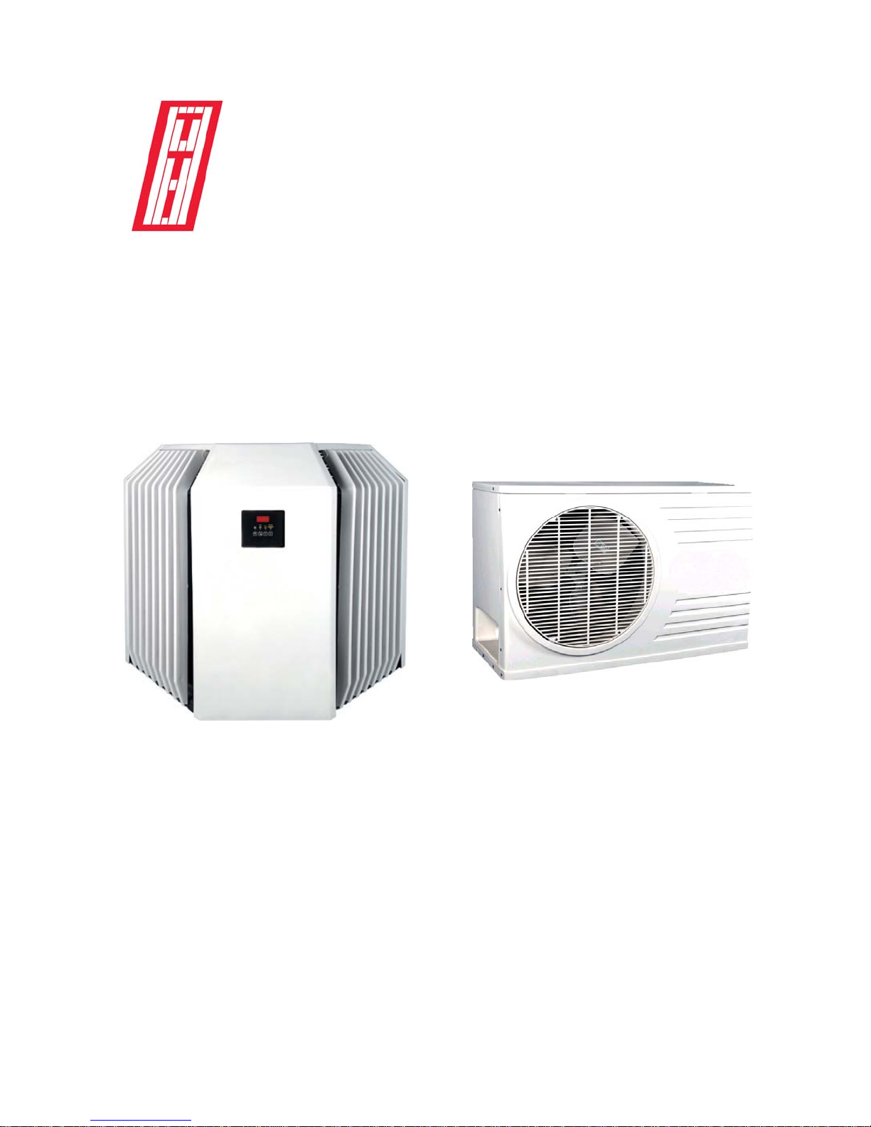
POOL HEAT PUMP
OWNER’S MANUAL
INST ALLA TION MANUAL
No : 2004.1
GENERA TION MODEL ECLIPSE MODEL
READ THESE INSTRUCTIONS CAREFULLY BEFORE INSTALLING OR
USING YOUR NEW POOL HEAT PUMP.
Page 2

TABLE OF CONTENTS
Introduction...............................................................................................p.3
A Cost-Efficient Heater
How Does It Work?
Low Maintenance
Selecting the location.................................................................................................p.4
Supply and Accessibility
Other Recommendations for Spas
Water Inlet and Outlet Connections..............................................................p.5
Basic Connection
Chlorinators, Brominators and Other Automatic Systems
Pressure-Type Chlorinator or brominator
In-line Chlorinator or Brominator
Salt Chlorinator
Dual Units Connection
Pool and Sp a Connection............................................................................p.8
Using One Pump and One Filter for the Pool and the Sp a
Using Independent Pumps and Filters for the Pool and the Spa
Electrical Connection..................................................................................p.9
Maintenance...........................................................................................p.10
Cleaning
Winterizing
Seasonal Start-up
Water Deviation
Water Maintenance.....................................................................................p.13
Why Perform Water Maintenance?
Water Chemistry
Sanitizers
What to Do?
Swimming Pool Heat Pump Control.....................................................p.18
Solving Problems........................................................................................p.24
Questions and Answers.............................................................................p.25
Warranty..................................................................................................p.26
Page 3
INTRODUCTION
A Cost-efficient Heater
Y our new pool heat pump will help you save money compared to other types of pool heat-
ers.
In fact, even if your pool heat pump has a lower heat capacity which makes it run for 24
hours a day , the pool heat pump remains the most economic system, because of the use of state
of the art technics in thermodynamics.
How Does It Work?
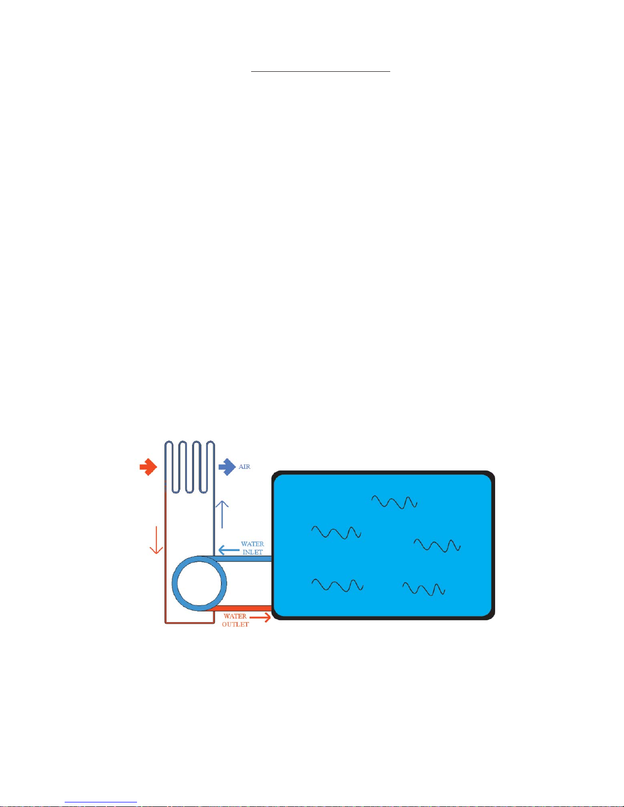
Y our pool heat pump works just as a water pump does. Whereas a water pump is tranferring
water from one place to another , your pool heat pump is transferring heat between the surrounding air and your pool water. Moreover , your pool heat pump is not producing heat with the energy
it is consuming just as a water pump is not producing water. It is because of this principle that
your pool heat pump may attain efficiency ratios going up to 600% or 700% in the best climatic
conditions. This means that for each kilowatt your pool heater consumes, it is transfering 6 or 7
kilowatts from the surrounding air to the pool water . The difference is astronomical compared to
oil, gas or electric resistance heaters yielding only 80 to 95% output. But it is true to say that the
output of traditional pool heaters stays constant at any outdoor climatic conditions whereas the
output of a pool heat pump varies. However , even when temperatures are cooler the pool heat
pump continues to transfer heat between air and water and it stays the best choice for temperatures down to 5 Celcius (41 Fahrenheit) overnight.
Y our pool heat pump is designed for lower maintenance at a lower cost. But if you want
your pool to be heated efficiently , you must follow the advice supplied in this manual.
3
Low Maintenance
Page 4

SELECTING THE LOCATION
The area you choose for your pool heat pump is very important. Y ou must consider the
following.
Air Supply and Accessibility
Y our heat pump uses the surrounding air to work. It is very important that you make sure
there is enough air circulation around the heat pump. Do not install the heat pump in a closed
space like a garden shed, a garage, or a basement.
The table below indicates the minimum distance from the heat pump that any object should
be located.
Generation (CP) Eclipse (MP)
(1) facing the coil surfac es
(2) facing other surfaces
(3) facing fan *
(4) facing servi ce panel
* Objects should be placed as far as possible from where the air is discharged.
2 feet = 61 cm
10 inch = 25.4 cm
4 feet = 122 cm
2 feet = 61 cm or accessible
2 feet = 61 cm
14 inch = 35.5 cm
4 feet = 122 cm
2 feet = 61 cm or accessible
3
2
2
1
1
4
2
3
CP Model MP Model
Other Recommendations
Do not install the heat pump under a roof. Doing this will protect the heat pump from being
buried by snow or receiving heavy rainfall from the roof that does not have gutters.
Also, make sure that the digital control does not face the sun. The control will not break
but its digital display will be more difficult to read.
If you have an automated sprinkler system for your lawn, make sure that the heat pump is
not showered by a sprinkler.
The pool heat pump should be installed on a firm and leveled surface, preferably on a
concrete slab or something equivalent.
Keep in mind that the heat pump will cause condensation. Therefore water will be dripping from the heat pump.
1
4
4
Page 5
WATER INLET AND OUTLET CONNECTIONS
)
)
W
For your own security , and to ensure proper operation of the unit, the water connection must be performed by a qualified person as per all applicable national, provincial, state or local codes.
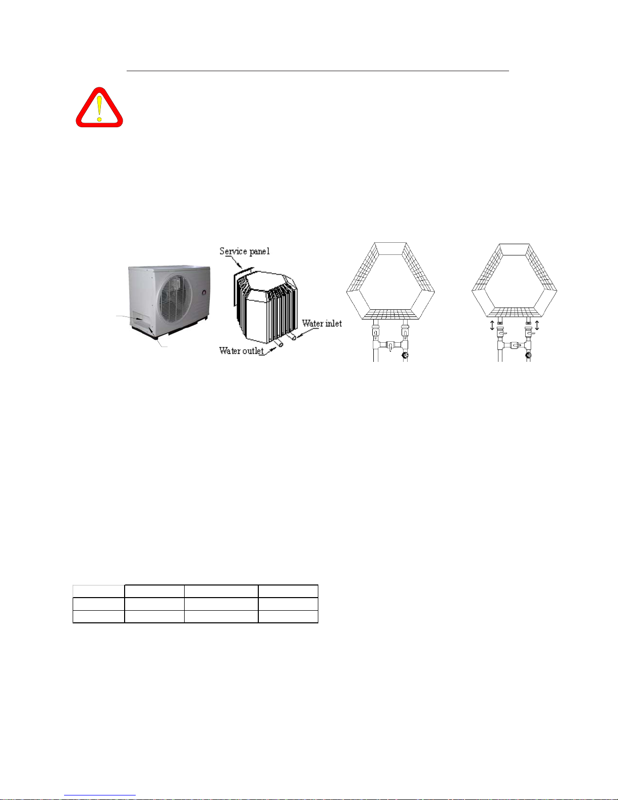
For all Eclipse (MP) models, connection pipes are 1 1/2 inches in diameter . For all
Generation (CP) models, the connection pipes are 2 inches in diameter. For all the pool
heaters, we recommend (obligatory for the Eclipse series) the installation of a set of valves
allowing to isolate the pool heater from the filtration system when necessary . (See the drawing
below.) Moreover , you have to make sure that your pool heat pump may be disconnected from
the pool pipes without having to stop the water pump or without losing great quantities of water .
Front View
ater Outlet
Water Inlet
a
Set of valves
a
T o adjust the water flow going through the pool heater , please adjust the by-pass valve (a)
in the following way:
MP30 - MP50 : 3/4 opened
MP70 : 1/2 opened
All CP’s : Closed - the internal calibrated valve regulates the water flow , exception
for those who have a water pump of 2hp or greater , adjust the valve to obtain the flows listed
below.
If the previous settings are not respected, the pump or the pool heater may be over-
charged and result in failure of your equipement.
Y our water pump must provide the quantity of water indicated in the table below . These
numbers must be used for each pool heat pump installed. A flow meter must be installed on the
water inlet of the pool heater to know the exact water flow . Caution : many flow meters require a
long distance of straight tubing on the inlet side to offer an adequate measurement.
Minimum Ideal Maximum
Eclipse 15 GPM(US) 20-30 GPM(US) 50 GPM(US
Generation 25 GPM(US) 40-50 GPM(US) 65 GPM(US
GMP(US) : American gallons (3,78l) per minute
5
Page 6
Basic Connection
P-trap
Check-Valve
Chlorinators, Brominators and Other Automatic Systems
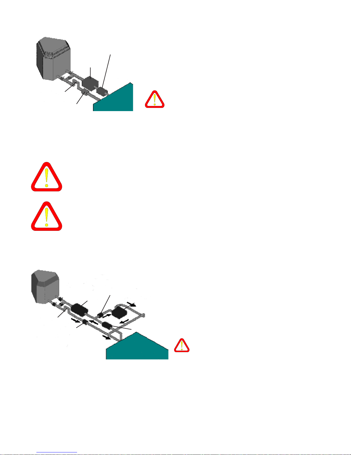
Any automatic distribution system of chemical products, chlorine, bromine or others,
must be installed after the outlet of water from the heat pump. The warranty of the
heat pump will be voided for any installation that is not in accordance with
this rule.
The use of a brominator or a chlorinator tends to lower pH and total alkalinity because
of the chemicals in it. If you use such a product, you must check the quality of the
water regularly. (Addition of sodium bicarbonate is recommended to restore the
balance.) (See the section Water Maintenance on p.12.)
Water pump
Filter
This connection method is strongly recommended
to enhance the life-span of your pool heat pump.
If you connect the unit this way , you have to pour
chemicals directly into the pool or the spa, as far as possible from the water supply point.
Do not pour chemicals in the skimmer or at the
bottom of the pool, if you have a drain, because of
the possibility of migration of the chemicals to the
heater .
P-trap
Check-valve
Pressure-type Chlorinator or Brominator
The pressure-type chlorinator or
brominator takes a small amount of water from
the outlet side of the filter, adds chemicals to it
Filter
Check-valve
Chlorinator
Water pump
and returns this highly concentrated solution to
the pool. The check valves must be highly resistant to corrosion. Use only a check-valve either supplied or recommended by the chlorinator (brominator) manufacturer .
The p-trap should be installed higher than
the top of the chlorinator (brominator) to
prevent migration.
6
Page 7
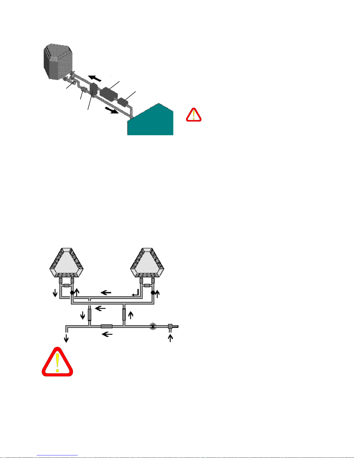
P-trap
Check-valve
In-line Chlorinator or Brominator
The in-line chlorinator or brominator
should be installed on the pool water return line,
between the heat pump and the pool. This type
of chlorinator (brominator) should be installed
Filter
Water pump
as far as possible from the heat pump. Install a
check-valve between the heat pump and the
chlorinator (brominator).
Chlorinator
The p-trap should be installed higher than
the top of the chlorinator (brominator) to
prevent migration.
Salt Chlorinator
Salt chlorinators are made to be installed like in-line chlorinators. Therefore, they must
be installed in accordance with the “In-line Chlorinator or Brominator” connection directives, else the warranty of the heat pump will be voided. (See the section “Water Main-
tenance” on p.12 and the section «Salt Generated Chlorine» on p.15 for more information on
operating salt chlorinators.)
Dual Unit Connection
For some larger pools, it may be necessary to install two units in parallel. In this
case, double the distances recommanded in
the table 1 of the page 5. Never place two MP
models coil against coil, fan against fan or coil
6
1
3
2
6
4
5
against fan.
1,2 and 3 : calibrated valves
4 : filter
5 : water pump
6 : flow meters
When the access to a heat pump is shut off, the water flow passing through this heat
pump will be redistributed among all others. Therefore, the valves mus be re-adjusted to meet the water flow requirements.
7
Page 8
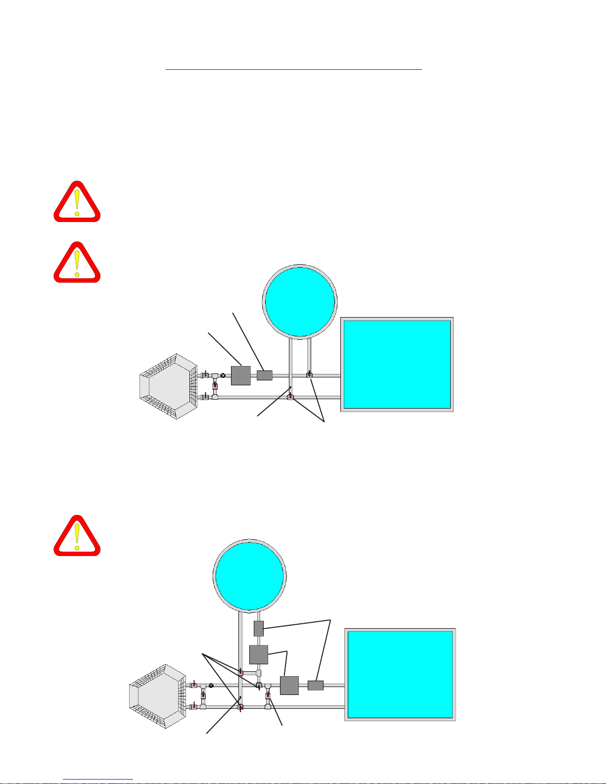
POOL AND SP A CONNECTION
Using One Pump and One Filter for the Pool and the Spa
An installation featuring a single pump and a single filter for the pool and the spa is easier
and more economical. Using home automation, it is possible to always keep the pool and the
spa to the desired temperature. Otherwise, it is always possible to have only the desired system
functioning by positioning the valves to have the water circulating in the pool or in the spa.
1) It is more difficult to maintain ideal levels of chemicals in the water when using a
single filter because this type of installation prevents the pool or the spa from being
filtered. An independent home automation system with automatic valves can reduce
this problem, or you must be very assiduous in maintenance.
2) For the pool heat pump to automatically detect the switch over from pool to spa and
vice versa, a flow switch must be added on the spa line.
Water pump
Filter
Flow switch
Spa
Pool
Manual or automatic 3
ways valve
Using Independent Pumps and Filters for the Pool and the Spa
An installation featuring independant pumps and filters for the pool and the spa is a little
more complicated and expensive. However, it is more advant ageous because the pool or the
spa is never left without filtration. W ater is therefore easier to maintain.
1) For the pool heat pump to detect the change made either manually or by an
independant system, a flow switch must be added on the spa line.
Spa
Manual or automatic 3
ways valve
Flow switch
Water pumps
Filters
Pool
Ball valve
8
Page 9
ELECTRICAL CONNECTION
For your own safety , and to ensure proper operation of the unit, the electrical connections must be performed by a qualified electrician as per all applicable national, provincial, state or local electrical codes.
A breaker must be installed near the heat pump in an accessible area.
Never open the electrical box without shutting off all power sources to the heat pump.
If your heat pump features a water pump control option, do not forget to shut off the
breaker to this water pump.
The identification plate on the heat pump identifies all voltage requirements.
If the supply cord is damaged, it must be replaced by the manufacturer or its service
agent or a qualified electrician to avoid electrical shock.
9
Page 10

MAINTENANCE
Before performing any maintenance on the heat pump you must turn off the breaker of
the electrical supply line.
Cleaning
T o ensure optimum performance of the heat pump, follow these recommendations:
- Backwash the filter of the pool on a regular basis in order to ensure proper flow rate
through the pool heater;
- Keep the surfaces of the coil clean and free of any obstruction such as papers, leaves or
other debris;
- Carefully clean the unit using a soft, non abrasive and bleach free cleaner , and rinse
using a garden hose without the nozzle;
- Check the drainage holes of the base of the unit to make sure that they are clean and
unobstructed. (This prevents water from accumulating in the heat pump.)
Winterizing (Cupro-nickel heat exchanger)
If you close the swimming pool during the winter season, it is essential to drain the unit in
order to prevent the formation of ice in the condenser (water section). To winterize the heat
pump, you must :
1. Stop the unit;
2. Shut off the breaker of the heat pump electrical supply line;
3. Disconnect the water intlet and outlet connections (See “Water Deviation” for details.);
4. Freely flush the condenser with tap water . Completely drain the system using air pres-
sure or vaccum system. We do not recommand putting anti-freeze into the heat pump
pipes, but if you chose to put some, make sure it is compatible with copper , otherwise, it
would do more damage to the condenser than small quantity of ice would;
5. If the heat pump is left outside during winter , protect it with a waterproof cover .
Winterizing (Titanium heat exchanger)
If you close the swimming pool during the winter season, it is essential to drain the unit in
order to prevent the formation of ice in the condenser (water section). To winterize the heat
pump, you must :
1. Stop the unit;
2. Shut off the breaker of the heat pump electrical supply line;
3. Loseen the bypass valves (photo A) and let the water drain out (See “Water Deriva
tion” for details.);
4. Unscrew the small cap (photo B) with the help of two wrenches (photo C) and freely
flush the condenser with tap water. Completely drain the system using air pressure or
vaccum system. Store the small cap during winter .
5. Block the opening of either the water inlet or outlet pipe (photo D) with your hand and
blow air into the pipe not covered by your hand to flush out the water completely . If the heat
pump is left outside during winter , cover it with a waterproof cover.
10
Page 11
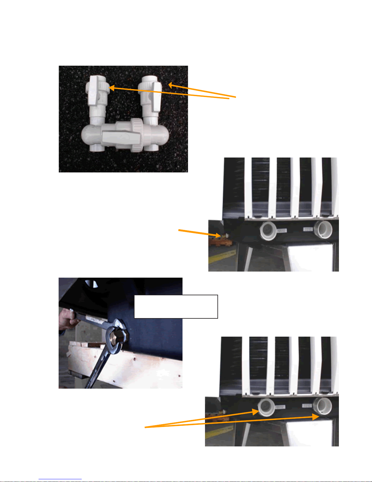
A.
Winterizing (Tit anium heat exchanger)
Loosen bypass valves
B.
C.
Brass cap
Unscrew brass cap
D.
W ater inlet and outlet pipes
11
Page 12
Seasonal Start-up
Before starting the pool heat pump for the first time of the season, you must :
1. Verify and adjust the quality of the pool water (see chapter "W ater Maintenance" to find
out about the amount of chemicals to be used in your swimming pool);
2. Make sure that the electrical breaker of the pool heat pump is in the off position;
3. Connect the heat pump to the water circuit;
4. Clean the pool filter and make sure that the water is flowing adequately through the pool
return line;
5. Switch on the breaker of the heat pump electrical supply line.
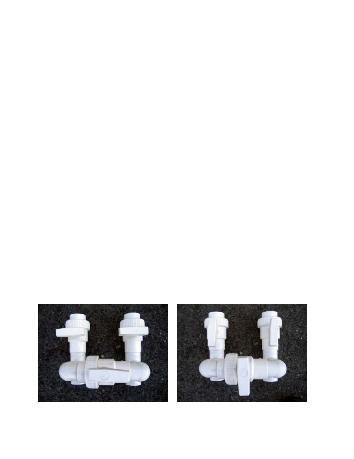
Water Deviation
Some maintenance operations(System Shock) require that the pool heat pump be isolated from the filtration system to keep the heat exchanger from suffering damage over time. By
using the method of deviation, you will be able to block access of pool water from entering the
pool heat pump. T o derive the water , you must :
1. Stop the unit.
2. Open the by-pass valve and close the water inlet and outlet valves (Photo 1.)
After a longer period of inactivity (1 week or more):
3. At the beginning of spring, when you prep are your swimming pool, make sure that the
water is stable by checking the pH, alcalinity and chlor level before starting your pool heat
pump. (T o find out about the amount of chemical products to use in your swimming pool,
consult the chapter on "Water Maintenance" in the manual.)
4. When the water is stable, you can close the by-pass valve and open the water inlet and
outlet valves (Photo 2) to end the deviation process.
Photo 1
Photo 2
12
Page 13

pool 1.0-3.0
pool 2.0-4.0
WATER MAINTENANCE
Why Perform Water Maintenance?
Contrary to traditional heat pumps that treat air only , pool heat pumps deal with water and
are much more sensitive. This is mainly caused by water chemistry . Only you, the owner of the
heat pump, can control the chemistry of your swimming pool water to avoid premature degradation
of your pool heat pump.
Water Chemistry
Many chemicals are used to control the quality of swimming pool water. W e use different
types of chlorine or bromine to control microorganisms and algae. We also use various products
to regulate pH and other aspects of the water chemistry. Every product added produces an
effect on water chemistry that must often be balanced with other chemical products. For example,
trichlor addition induces a diminution of pH and of total alkalinity (T A). We must balance those
effects by adding sodium bicarbonate (baking soda).
Some organizations, like the NSPI (National Spa & Pool Institute), publish standards on
pool water chemistry. Those standards are made to protect swimmers and swimming pool
equipments, particularly their metal parts, copper , steel and even stainless steel, that will corrode
under the effect of bad chemistry . Generally , if the equipment can be damaged by bad chemistry ,
this can also be a health hazard. (See the following table for the standards.)
Table 1: Chemical Products Concentration in Pool W ater S tandard
Minimum Ideal Maxim um
pool 3.0
Free chlorine* 1.0
Combined c hlorine* None None 0.2
Brom ine* 2.0
pH 7.2 7.4 - 7.6 7.8
Total alkalinity * 80 80-120 150
Total dissolved solids* 300 1000-2000 3000
Calcium hardnes s * 150 200-400 500-1000
Cyanuric ac id* 10 30-50 150
Salt * (salt c hlorinator) None None 3000
*Ppm: parts per million
spa 3. 0-5.0
spa 3. 0-5.0
spa 10.0
pool 4.0
spa 10.0
Your heat pump, just as any type of pool heater (gas, oil, electric, etc.), features some
metal parts that can be damaged by bad chemistry. The condenser of your pool heat pump is
made of a copper alloy that, as resistant as it is, is sensitive to pH. That is why we strongly
recommend testing the quality of the pool water regularly . These controls must be made on a
weekly basis and must at least feature the following: chlorine or bromine, pH and T A. Moreover ,
13
Page 14

we suggest having the pool water tested by a professional (often free of charge) once a month.
The water of the pool or spa must be maintained within the standards included in this
manual. Any negligence to do so, will void the warranty. These standards are from the
NSPI and are common throughout the swimming pool industry; they are not particular to T urcotte
heat pumps.
The most important factor for the durability of the pool heat pump is the pH because the
capability of the water to cause the degradation of metal is directly related to it. Let’s also
mention that T A is the measure of the capacity of water to resist to pH variation; therefore it is as
important. T aylor , an important manufacturer of pool water test kit for professionals states:
“Corrosive water will dissolve copper piping and heat exchangers and leave stain on
pool walls.” [T aylor , A T esting & T reatment Guide part #2004B, p.35]
“The result is a highly unbalanced water condition resulting in damage to copper heat
exchangers, light rings, stainless steel ladders an concrete pool surface.” (T alking about
acidity and low T A) [Taylor , A T esting & T reatment Guide part #2004B, p.1 1]
Below is a chart presenting pH associated to concentrated solutions of various chemical
products for pools.
Table 2: pH of V arious Chemical Products for Pools
Chemical pH
Chlorine
Trichlor (puck s) 2.5-3.0
Sodium Dichlor 6.8-7.0
Lithi um Hy pochlorite (powder) 10. 7
Calcium Hypoc hlorite (cylinder) 11.8
Liquid Chlorine 13
Bromi ne (t abs ) 3.6
pH Regulating P roduc t s
Muriatic A c id 0.1
Dry Aci d 1. 4
Cyanuric Ac id 3
Sodium B i carbonate 8.3
Sodium S esquicarbonate 10.1
Soda A s h 13
14
Page 15

Sanitizers
Sanitizers are products used to purify water , to relieve it from microbes and algae. They
are chlorine, in its different forms, and bromine in the case of the pools. Each of them has its
advantages and inconveniences. They are sometimes basic, sometimes acid. They can have
different impacts on water chemistry and can necessitate various chemical products to counterbalance those impacts or to stabilize them. W arm water is more difficult to maintain, it necessitates
greater quantities of sanitizers and, therefore, greater quantities of other chemical products.
Never pour any sanitizer directly into the water intake (skimmer) without having deviated
the water from the pool heat pump previously. (See the section "Water Deviation",
p.11.)
NOTE: The use of a floatting distributor is recommended as an alternative to pourring chlorine
directly into the skimmer. Maint aining the chlorine level using this method can however be more
difficult because the water flow dissolving the chlorine is less important on the top of the pool than
in the water pump system.
Shock Treatment
Before performing any shock treatment, deviate water from the pool heat pump to
prevent chemical products from damaging it
1) Trichloro-s-triazinetrione (TCCA or trichlor or pucks)
Trichlor is a very common and practical sanitizer because it dissolves into hypochlorous
acid, a powerful sanitizer, and into cyanuric acid, a st abilizer improving the duration of its efficiency .
However , it produces 2 acids that contribute to lowering pH and AT of the pool water . This can
cause severe damage to the pool and to its system because of corrosion:
“…having a strongly acidic pH, TCCA tablets will reduce total alkalinity and, if not moni-
tored, low total alkalinity will cause corrosive damage to the pool.” [Taylor, A Testing &
Treatment Guide part #2004B, p.26]
Usage of trichlor requires the addition of sodium bicarbonate to higher the pH and TA
level. Warning: many users testing only pH will be tempted to use sodium carbonate, or pH+,
however this product does not increase T A level and pH will decrease back rapidly . As acidic
water is also most of the time very clear because it is free of microorganisms, T.T.I. wants to
remind you to test water regularly to avoid problems caused by acid water . Clear water is not a
synonym of good quality water.
NOTE: With trichlor, it is possible to use what is called a chlorinator . A chlorinator is an
automatic chlorine distribution system, but in no case it is controlling pH and TA of
water. Thinking their system is completely automatic, users of those systems of ten
neglect to test their water . Moreover, make sure that your heat pump installer has modified the
circuit of your chlorinator in a manner to prevent it from pouring out its concentrated solution of
chlorine into the pool heat pump. (See p.7)
15
Page 16

2) Bromine
Bromine is a very good sanitizer. It is safe and practical. It does not require any st abilizer
and it does not cause irritation nor has any odor . Furthermore, its efficiency is independent from
pH of water. However, it is acid and it destroys T A. W ater that is acid and low in TA becomes
corrosive and disintegrates metallic pieces of the pool system, including the heat exchanger of
your pool heat pump. Therefore, it is imperative to test water frequently, even if water is very
clear, to avoid problems caused by water acidity . Acid water is often very clear because it is free
of microorganisms, but it is damageable and of bad quality .
NOTE: with bromine, it is possible to use what is called a brominator. A brominator is
an automatic bromine distribution system, but in no case it is controlling pH and T A of
water. Thinking their system is completely automatic, users of those systems of ten
neglect to test their water. Moreover , make sure that your heat pump installer has modified the
circuit of your brominator in a manner to prevent it from pouring out its concentrated solution of
bromine into the pool heat pump. (See p.7)
3) Sodium hypochlorite (liquid chlorine)
Liquid chlorine is completely soluble in water and does not leave any residue in pool
water, but it decomposes rapidly , even when stored, and require usage of a stabilizer like cyanuric
acid. As it is alkaline, it contributes to raise pH and TA. High pH and TA can contribute to the
formation of a deposit of limestone on the condenser of the heat pump, creating an isolating
layer on the heat exchanger and reducing the heat pump efficiency .
4) Calcium Hypochlorite (granular or stick chlorine)
Granular chlorine is easy to use and dissolves rapidly . On the other hand, it increases pH,
T A and calcium hardness significantly . Like with liquid chlorine, high calcium hardness, pH and
T A can contribute to the formation of an isolating layer on the heat exchanger reducing the heat
pump efficiency .
5) Salt Generated Chlorine
A salt chlorinator produces bleach and other components through the electrolysis of salted
water. The proccess does not affect pH nor T A. However , users of those systems must test
their pool water on a regular basis since pH and T A may vary because of other factors.
Salt concentration must also be tested because a salted solution contains ions that may
corrode the cupro-nickel heat exchanger. Do not put more salt in your system than the
quantity recommended by the manufacturer of the salt chlorinator and do not exceed
the recommended concentration. Usually , if the water tastes salted, it contains too much salt
and can damage the heat exchanger of the pool heat pump.
NOTE: Other types of sanitizers exist; all of them have their advantages and
inconveniences. What is truly important to keep in mind is that pool water is something
that should be maintained regularly and that should be balanced according to standards
established throughout the pool and spa industry .
16
Page 17

What to do?
The purpose of maintaining the water of your pool is not only to protect the swimmers, but
also to improve the working conditions of your pool equipment, particularly of your pool heat
pump to increase its durability and its efficiency . To achieve this goal, the user must:
1. T est pool water regularly (chlorine or bromine, pH and total alkalinity);
2. Balance the pool chemistry within the level of the standards using the appropriate products;
3. Protect the pool heat pump whenever the water should be beyond the standards.
1) T esting
We highly recommend checking the level of chlorine or bromine, and the level of pH and
T A at least once a week. Moreover , we suggest that you have your water tested professionally
once a month, particularly the following variables:
· Calcium hardness: a low calcium hardness level implies corrosive water that can
damage your pool heat pump. A high level of calcium hardness contributes to the
formation of deposits on the surface of the heat exchanger reducing the efficiency of
the pool heat pump;
· T otal dissolved solids: a high total implies a tendency of the water to corrode, therefore
gradually destroys the pool equipment;
· Copper level: a high copper level can indicate a degradation of the cupro-nickel heat
exchanger of the pool heat pump. So this can be considered as a warning urging you
to verify the pool water more often. For the users of copper algaecides, a higher level
of copper is normal; but verify if there is no gray-black stain deposit indicating the
saturation of the water in copper and a possible degradation of the heat exchanger;
· Stabilizer (cyanuric acid): a high level of cyanuric acid can damage the equipments
and, especially , is toxic for the swimmers.
2) Balancing
According to the levels given by the test results and according to the volume of water of
your pool, always balance the pool water in a manner that meets the standards. Y our swimming
pool service company can help you choose the proper chemical products and the appropriate
quantities. Always carefully follow the instructions given by the chemical products suppliers.
Never pour more into the water than prescribed.
Warning: any chemical product, acid or basic, is susceptible of provoking the
degradation of the heat exchanger of your pool heat pump. Never pour any chemical
product into the water intake (skimmer) of your pool to prevent the product from
damaging your pool heat pump.
3) Protecting the Pool Heat Pump
If you observe that your pool water is beyond the established standards, we urge you to
shut down your pool heat pump, to divert the water from it and to disconnect it from the plumbing,
as described in the section “Maintenance”, p1 1. Af ter, wash the heat exchanger using tap water .
17
Page 18
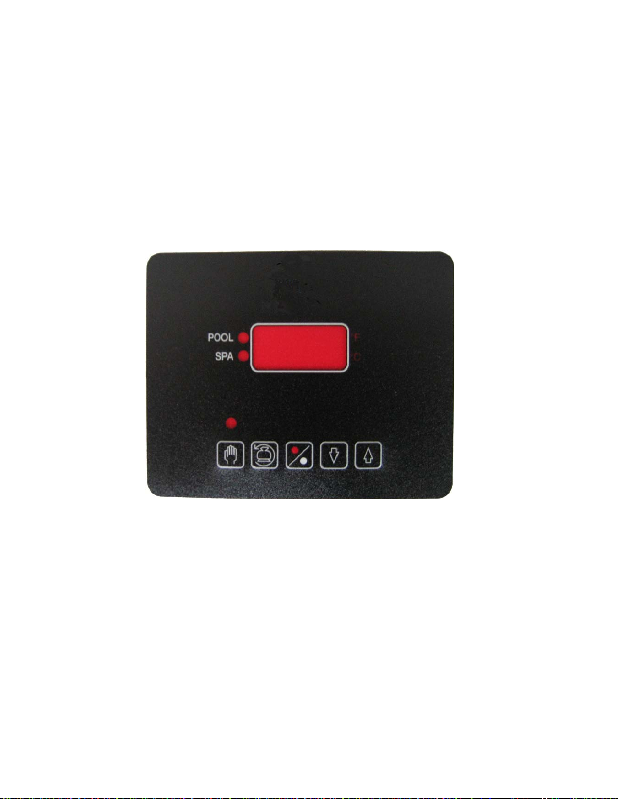
HP706
SWIMMING POOL HEATPUMP CONTROL
USER GUIDE MANUAL
18
Page 19
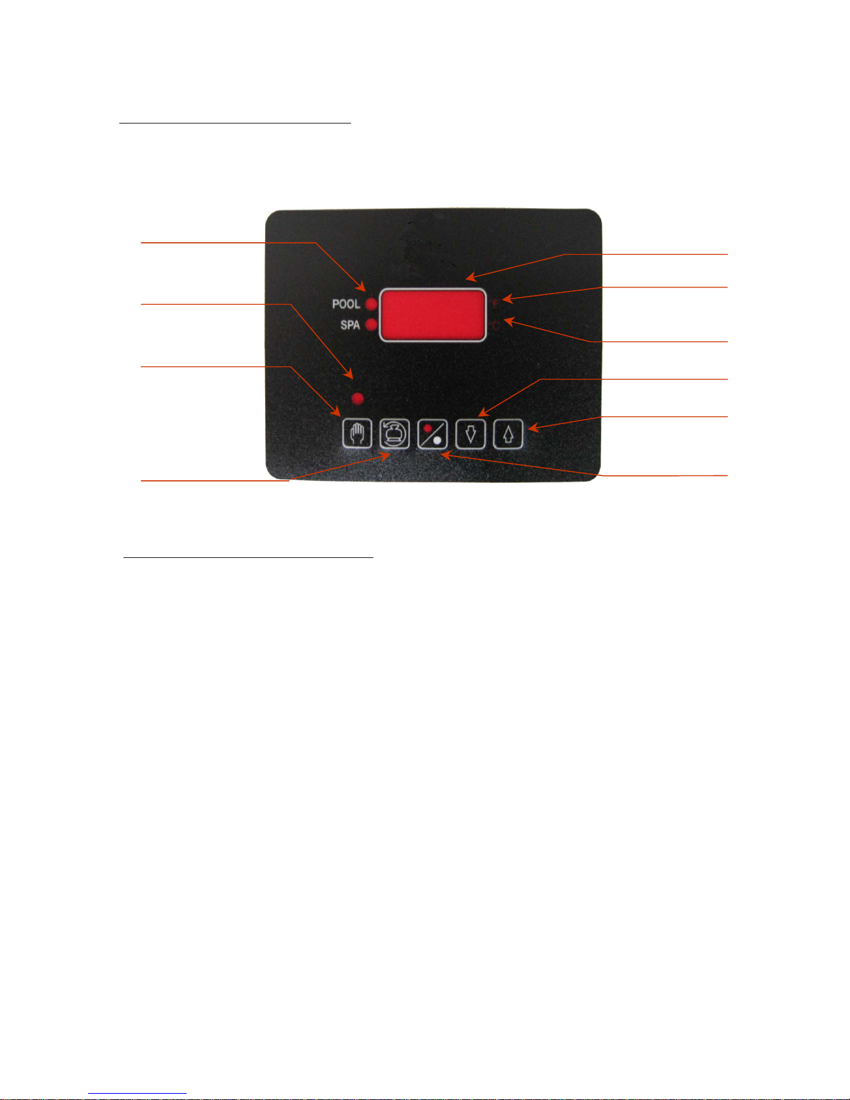
1. INSTRUMENT IDENTIFICATION
HEA T ON LED
POOL or SPA
SET UP MODE LED
DIGIT AL DISPLA Y
F DEGREES LED
C DEGREES LED
SET-UP KEY
BACKWASH KEY
2. DESCRIPTION OF FRONT PANEL:
DIGIT AL DISPLAY: Display normally shows the actual water temperature.
HEAT ON LED: Indicates that the heat pump is heating the pool or the spa.
°F LED: Indicates that the temperature is being displayed in °F.
°C LED: Indicates that the temperature is being displayed in °C.
SET MODE LED: Indicates the setup or adjustment mode.
DECREASE KEY
INCREASE KEY
ON/OFF KEY
ON/OFF KEY [%]: Turns the heat pump ON or OFF.
BACKWASH KEY [BACKWASH]: Hold for 3 seconds to activate the backwash mode.
SET KEY [SET]: Hold for 3 seconds to activate the setup mode.
INCREASE KEY [^]: Increases the desired or setpoint temperature.
DECREASE KEY [v]: Decreases the desired or setpoint temperature.
NOTE: The display may be changed in steps by pushing the [^] or [v] keys briefly, or automatically by holding down
the same key.
19
Page 20

3. OPERATION:
The control is first shipped in the OFF mode. The digital display will show «- - -» , indicating the OFF mode. THE
CONTROL MUST BE IN THE ON MODE IN ORDER TO CHANGE THE SETPOINT (THE DESIRED W ATER
TEMPERA TURE) OR HAVE ACCESS TO THE OTHER FEATURES! The setpoint is factory set at 70 °F.
a. SWITCHING THE HEATPUMP ON:
Hold the [SET] key for 3 seconds. The set mode LED will come on to indicate the set mode. Now touch the [%] key.
The display will now show the actual water temperature. If there is a demand for heat, that is if the actual water
temperature is lower than the desired or setpoint temperature, the Heat On LED, the compressor and fan will come
on. Note that each time the compressor turns off there will be a 5 minute delay before it can be turned on. After 8
seconds the set mode LED will go off.
b. SWITCHING THE HEA TPUMP OFF:
Hold the [SET] key for 3 seconds. The set mode LED will come on to indicate the set mode. Now touch the [%] key.
The display will now show «- - -». After 8 seconds the set mode LED will go off.
c. TO VIEW THE SETPOINT OR DESIRED TEMPERA TURE:
Hold the [^] key to display the setpoint or desired temperature.
d. TO VIEW THE DEFROST TEMPERATURE:
Hold the [v] key to display the defrost temperature.
e. TO CHANGE THE SETPOINT TEMPERA TURE:
Hold the [SET] key for 3 seconds. The set mode LED will come on to indicate the set mode. Now touch the [^] key to
increase the value or the [v] key to decrease the value. The adjustment range is from 70 °F to 105 °F ( 21 °C to 41 °C
in Celsius mode ). You have 8 seconds from the time that the last key was touched to make the adjustment. After 8
seconds the set mode LED will go off.
f. BACKWASH OPERA TION:
Hold the [BACKWASH] key for 3 seconds. The display will show [bac] to indicate the backwash mode. In this mode
the heatpump is turned off for 20 minutes in order to allow time for backwash. The heatpump will turn on
automatically at the end of the 20 minutes. If you would like to turn on the heatpump before the 20 minute delay,
simply press the [BACKWASH] key for 3 seconds ( when the circulation pump is returned to the filter position).
g. SWITCHING BETWEEN °F AND °C:
Hold the [SET] key for 3 seconds. The set mode LED will come on to indicate the set mode. Touch the [^] key and
the [BACKWASH] simult aneously to select the °F mode. T ouch the [v] key and the [BACKWASH] simult aneously to
select the °C mode. After 8 seconds the set mode LED will go off.
4. CALIBRATION:
Other features are available on the control which aid for both installation and servicing.
a. TO VIEW DEFROST TEMPERATURE:
To view the defrost temperature, push the [v] keys.
b. TO CANCEL THE 5 MINUTE ANTI-SHORT CYCLE DELA Y :
For a quick restart, push both the [BACKWASH] and [%] keys for 3 seconds. Ensure that the high and low pressures
are equalized.
20
Page 21

Another mode exists which permits the service technician to modify the calibration of the sensors as
well as different control parameters.
TO ENTER THE SERVICE MODE:
To access the service mode hold the [SET] key for 3 seconds. The set mode LED will come on to indicate the set
mode. Now hold both the [^] and the [v] key simultaneously for 3 seconds. The service mode LED will come on to
indicate the service mode. In the service mode, unlike the set mode, the control does not return automatically to the
normal mode 8 seconds after the last key was touched. To exit the service mode you must step through the
parameters until you come to the setpoint adjustment mode ( see i. on page 9 ). The first parameter is the water
sensor calibration.
c. WA TER SENSOR CALIBRA TION:
The digital display will show [CXX]. «C» represents the water sensor calibration mode. «XX» is the actual water
temperature in °F. If water sensor calibration is necessary, measure the water temperature with a precise digital
thermometer and adjust the digital display to show the same value using the [^] and the [v] key. To view or step to the
next parameter (defrost sensor calibration), touch the [SET] key.
d. DEFROST SENSOR CALIBRATION:
The digital display will show [cXX]. «c» represents the defrost sensor calibration mode. «XX» is the actual defrost
temperature in °F. If defrost sensor calibration is necessary, measure the temperature of the defrost sensor, installed
on the side of the evaporator, with a precise digital thermometer and adjust the digital display to show the same
value using the [^] and the [v] key. To view or step to the next parameter (defrost cut-in temperature), touch the [SET]
key .
e. DEFROST CUT-IN TEMPERA TURE ADJUSTMENT :
The digital display will show [LXX]. «L» represents the defrost cut-in temperature adjustment mode. The defrost cutin temperature is the temperature of the evaporator at which the defrost sequence is initiated. «XX» is the defrost
cut-in temperature in °F. This adjustment is factory set at 30 °F. If it is necessary to change this adjustment, adjust the
digital display to show the desired value using the [^] and the [v] key. The range of this adjustment is from 10 °F to 60
°F. To view or step to the next parameter (defrost cut-out temperature), touch the [SET] key.
f. DEFROST CUT -OUT TEMPERATURE ADJUSTMENT :
The digital display will show [HXX]. «H» represents the defrost cut-out temperature adjustment mode. The defrost
cut-out temperature is the temperature of the evaporator at which the defrost sequence is terminated. «XX» is the
defrost cut-out temperature in °F. This adjustment is factory set at 48 °F. If it is necessary to change this adjustment,
adjust the digital display to show the desired value using the [^] and the [v] key. The range of this adjustment is from
10 °F to 60 °F. To view or step to the next parameter (deadband adjustment), touch the [SET] key.
g. DEADBAND OR TEMPERATURE DIFFERENTIAL ADJUSTMENT :
The digital display will show [bXX]. «b» represents the deadband adjustment mode. The deadband is the differential
between the cut-in and cut-out water temperatures. «XX» is the differential in °F, This adjustment is factory set at ±0.4
°F ([b0.4] on the display). If it is necessary to change this adjustment, adjust the digital display to show the desired
value using the [^] and the [v] key. The range of this adjustment is from ± 0.1 °F to ± 1.0 °F. To view or step to the next
parameter (compressor defrost delay-off time adjustment), touch the [SET] key.
h. COMPRESSOR DEFROST DELA Y -OFF TIME ADJUSTMENT :
The digital display will show [dX.X]. «d» represents the compressor defrost delay-off time adjustment. The
compressor defrost delay-off time adjustment is the time that the compressor continues to operate after the defrost
temperature falls below the defrost cut-in temperature (ie. 30 °F) «X.X» is the delay time expressed in hours and
fractions of hours. This adjustment is factory set at 1.0 hour ([d1.0] on the display). If it is necessary to change this
adjustment, adjust the digital display to show the desired value using the [^] and the [v] key. The range of this
adjustment is from 0.1 hours to 1.5 hours. To view or step to the next parameter or to exit the service mode (setpoint
adjustment), touch the [SET] key.
i. TO CHANGE THE SETPOINT TEMPERA TURE OR TO EXIT THE SERVICE MODE:
Touch the [^] key to increase the setpoint or the [v] key to decrease the setpoint. The adjustment range is from
70 °F to 105 °F (21 °C to 41 °C in the °C mode). Y ou have 8 seconds from the time that the last key was touched to
make the adjustment. After 8 seconds the set mode LED will go off and the control will exit the service mode and
return to the normal mode.
21
Page 22

ERROR CODE LIST
CODE SY MPTOM PROBABL E CAUSE SOL UTION
DSO
SO
DSc
Sc
LP
Open-Circuit in evaporator
temperature sensor
Heat pump stopped
Open-Circuit in water
temperature sensor
Heat pump stopped
Short circuit in evaporator
temperature sensor
Heat pump stopped
Short circuit in water
temperature sensor
Heat pump stopped
Low pressure detected in
circuits
The evaporator temperature sensor
is incorrectly plugged in or defective
The water temperature sensor is
incorrectly plugged or defective
The evaporator temperature sensor
is incorrectly plugged in or defective
The water temperature sensor is
incorrectly plugged or defective
Loss of refrigerant
Defective captor or cable
Reset the heat pump from the
breaker
Call an authorized technician
Reset the heat pump from the
breaker
Call an authorized technician
Reset the heat pump from the
breaker
Call an authorized technician
Reset the heat pump from the
breaker
Call an authorized technician
Reset the heat pump from the
breaker
Call an authorized technician
Call an authorized technician
HP
HP4
Heat pump stopped
High pressure detected in
circuits
Working resumption when
the pressure becomes
normal again
4 high pressures detected
in circuits
Heat pump stopped
Defective fan
Dirty evaporator
Defrosting captor is defective
Water flow either slow or blocked
by an obstruction
Defective captor or cable
Water flow either slow or blocked
by an obstruction
Defective captor
Call an authorized technician
Clean the evaporator
Call an authorized technician
Reset the heat pump from the
breaker
Adjust the water flow
Call an authorized technician
Adjust the water flow
Clean pool filter
Reset the heat pump from the
breaker
Call an authorized technician
22
Page 23

CODE SYMPTOM PROBABLE CAUSE SOLUTION
Reset the heat pump from
the breaker. The control is
back to factory setting s,
Loss of memory in the co ntrol
PE
Resu mption of default par a meters
Error of communication
CO
between the control and the remote control
For th e hot-g as d efrosting option. Th e
defrosting operation has not finished in the
predefined time.
DF
Heat pum p stopped. Unplug the heat pump
and then plug it ba ck in to restart the co n tr ol.
If the problem persis ts, consider the
following options.
Power failure
Power output variation. The control
accepts a voltage range betw een 20 VAC
and 30VAC
Cables are incorre ctly plugged in or
defective
Defective control or remote control
Reversing valve blocked
Defrosting cap tor is defec tive
Compre ssor is in active in d efrosting
mode
call a n au t hor ized
technician to recover
personalized settings (not
covered by warranty)
Call an authorized
technician if th ere ar e still
problem s
Reset the heat pump from
the br eaker.
Check connections.
Call an authorized
technician
Reset the heat pump from
the br eaker.
Call an authorized
technician
Reset the heat pump from
the br eaker.
No water flow when pump op era ted by the
control (swimming pool pump control option
only)
FF
Resu mption of activities if w ater flow is
detected
Configuration of invalid option
CF
Loss of power
PF
Dis appear 10 s ec.
The valves of the heat pum p are closed
The pump is disconnected
The pipes a re o bstructed
The water flow detec tor is defective: the
water circulates in the heat pum p but is
not detected
Heat pump wa s disconnected
There was a po wer failure
Open th e valves of the
heat pump
Conn ect back the heat
pump
Unblock the pipes
Call an authorized
technician
Reset the heat pump from
the br eaker.
Reset the heat pump from
the br eaker.
Wait
23
Page 24

SOLVING PROBLEMS
Error Possible Causes Possible Solutions
Unit does not run.
The actual w ater
temperature increases
when the compressor
starts.
The heat pump ru ns
but does not ge ner a te
enough he at.
The heater seems to
have a water leak.
The defrost s e nsor
temperature decreases
when the compressor
starts.
The digit al contr ol
displays “888”.
Only the fan is runni ng. 1. Defrost mode.
1. Power is no t supplied to the
heat pump.
2. No demand for heat.
3. Anti cycle delay (5 minutes).
Water is not circulating in the
right direc ti o n.
1. Water is not circulating in
the right direction.
2. The heat loss of the pool
exceeds the heating capacity
of th e heat pum p.
3. The pool size exceeds the
specified capacity of the model
selected.
1. Normal - water caused by
condensation.
2. Water leak.
Normal.
The digital display is exposed
to the sunlight.
2. Anti cycle delay (5 minutes).
3. Defective compressor.
1. Make sure that the heat pump
electrical s u ppl y line breaker is
ON.
2. Make sure that the
temperature control is set at a
proper level. Adjust as required.
3. Whenever the compressor is
stopped, th e di gi tal control
imposes a minimal time delay of
5 minutes before restarting it to
allow gases to calibrate.
Check connections.
1. Check connections.
2. See “Heat Pump Sizing”
section on pa ge 4.
3. Use a more powerful model or
use more than one heat pump.
1. No action required.
(Install a derivation drain if
necessary.)
2. To verif y if it is a leak, you
need to stop the pool heat pump
unt i l all the condensation has
disappeared. Verify if there is
water remaining around the
machine after 24 to 48 hours.
(See p. 18 Q2)
No action required.
Make shade on the display to
distinguish lights that are ON
from those that are OFF.
1. No action required.
2. No action required.
3. Call an authorized service
technician.
24
Page 25

QUESTIONS AND ANSWERS
1) Is it possible that my pool is losing water since my pool heater was installed?
-Y our pool is not losing water , but because the pool water is at a higher temperature, there
is more evaporation. When the difference of temperature between the pool water and the
surrounding air is increased, more evaporation happens.
2) Some water drops beside my pool heater, does my pool heater have a leak?
-It probably does not. The water droping from your pool heater must come from
condensation of the humidity on the evaporator of your pool heater, just as condensation forms
on a cold water glass for example. But, if you really think a leak could be present in your pool
heater and want to be sure, you can stop the filter pump and the pool heater, or stop the pool
heater and use the by-pass set of valve to prevent water from accessing your pool heater . Wait
until the water evaporates beside the pool heater and have the water circulates again into the
pool heater without putting the pool heater on. If water drops, it comes from a leak, not from
condensation.
3) My pool heat pump indicates a temperature that is different from the temperature
indicated on my pool thermometer. Does my pool heat pump have a problem?
-Chances are that it does not. Y our pool heat pump features calibrated digital control and
sensors. Most of the time, the problem comes from the pool thermometer. Even though the
mercury thermometer is precise, its box is not and the thermometer is often not in line with the
graduations written on the box. In this condition, the thermometer reads a temperature higher or
lower than the real pool temperature. T o measure the temperature of water , you can use a mouth
thermometer on which the graguations are written directly .
-When the pool features a bottom drain, it is possible that the pool heater shows a
temperature 1 or 2 degrees lower than what is measured on surface. This situation is normal
since the water at the bottom of a pool is always cooler than on surface.
4) Since the installation of my pool heat pump, the pressure in my filter pump has risen,
is it normal?
-Y es. The new heat pump, as well as the new tubing, is an added resistance to the water
flow. Therefore, it is normal to have a rise of the pressure of 5 to 7 psi after the installation of a
new pool heat pump.
5) Why isn’t the pool water heating as my pool heat pump is working?
-3 cases exist as the pool heat pump is functioning:
The heat pump provides more energy than the pool is losing, the temperature rises.
The heat pump provides as much energy as the pool is losing, the temperature is stable.
The heat pump provides less energy than the pool is losing, the temperature lowers.
We should not forget that the pool heat pump efficiency varies with the operation conditions
and that the energy losses of the pool are relative to the outdoor temperature, to the wind, to the
size of the pool and to many other factors.
25
Page 26

WARRANTY
POOL HEA T PUMPS
EXCLUSIVE LIMITED WARRANTY
5 YEAR - W ARRANTY ON ALL P ARTS INCLUDING ELECTRONICS FOR
RESIDENTIAL SECT OR ONLY
2 YEAR - W ARRANTY ON ALL SERVICE LABOR
(ASK YOUR RETAILER FOR ADDITIONAL W ARRANTY INFORMA TION)
5 YEAR - W ARRANTY ON TURCOTTE CUPRO-NICKEL HEA T EXCHANGER
(5 YEARS P AR TS; 2 YEAR LABOR / NO W ARRANTY IF USED WITH SAL T CHLORINA T OR)
20 YEAR - W ARRANTY ON TURCOTTE EXCLUSIVE RESIN CABINET
LIFETIME LIMITED W ARRANTY ON TIT ANIUM HEAT EXCHANGER
P ARTS ONL Y
26
Page 27

POOL HEA T PUMPS
LIMITED WARRANTY
5YEARS P ARTS & 2 YEARS LABOR ST ARTING FROM THE INST ALLA TION DATE
A vailable only for brand new products purchased
Parts: As described in this agreement, we will replace all parts judged defective or having a fabrication
flaw if they were used under normal conditions for all TURCOTTE pool heat pumps for the duration of this
agreement. Pool Heat Pumps are warranted for (5) Five Years Parts (2) years labor .
heat exchanger is not under warranty if used with a salt chlorinator . Also, the titanium tube portion
only , of the heat exchanger, has a lifetime warranty for as long as the heat pump is installed at the original
address of the original owner or purchaser. On the other hand, the heat exchanger reservoir carries a 5 year
warranty .
Labor: W e will be responsible for labor in relation to the service required to replace defective parts.
On the other hand, we will not be responsible for the labor related to the installation of a replacement unit if
the present one cannot be repaired.Replacement of defective parts, as per this agreement, must be performed during normal work hours. W e will not be responsible for labor charges under this agreement if
there were no defective part, as per this agreement.
Owner: The warranty service agreement remains in effect until the expiration date of the here said
agreement and as long as the product remains at the original installation address and was installed according
to manufacturer’s recommendations located in the owner's manual. This agreement may be transferred to a
second owner of the same address by sending a written request to T .T .I. accompanied by a copy of a
notarized transfer of ownership document and a check or money order of $70.00 covering transfer and
administrative fees within 60 days.
The cupro-nickel
Limited Responsibility: W e will repair the heat pump under warranty as long as the cost of repairs
does not exceed the cost of the heat pump. If the cost of repairs exceeds the cost of the machine, the
machine will be replaced by an equivalent unit according to availability .
Termination: All our obligations cease at the anniversary date of the said agreement which starts on
the installation date.
Exclusion: This warranty agreement does not cover products or parts which may have been subject
to alteration, abuse, abusive usage, accident, omission or stability of the installation, excessive voltage, acts
of God, corrosion, commercial use, or any other usage not approved by T .T .I. This warranty does not
cover the following items:
• All equipments not approved by T.T.I.
• Base and Support
• Paint, finishing or rust
• Cost for shipping parts directly
• All applicable taxes on parts and labor when required
• Decorations and borders
• Fuses and breakers other than the product’s
• All electrical services required beyond the warranted equipment
• Adjustments
27
Page 28

• Chemical damage due to improper maintenance of pool water as described in the
owner's manual (excluding pool heat pumps containing a titanium heat
exchanger) (See chapter “Water Maintenance” in the owner’s manual)
Consumer’s Responsibility: The warranty card included with the purchase of a TURCOTTE pool
heat pump must be sent back to T .T .I. within 30 days following receipt. Y ou are responsible for the cost of
all service calls made in regards to instructing you on how to operate your system or to correct an improper
installation of the system not approved or not described in the manufacturer’s instruction manual. This
agreement does not cover the cost of preventive maintenance, we suggest that you contact an authorized
TURCOTTE service center for your annual inspection, it is the owner’s responsibility to have an annual
inspection and preventive maintenance of the equipment. This agreement does not cover cleaning, lubrication and adjustment of items such as evaporators, condensers, or air exchangers. You must provide reasonable access to the unit(s) for servicing at all times. Any work required to restore the property after servicing, is solely the consumer’s responsibility . Also, it is the owner’ s responsibility to have proper bonding of
the equipment to avoid heat exchanger corrosion.
Overtime: Overtime is not covered under this agreement, you will be invoiced for all overtime if you
decide to have the service performed outside regular business hours.
Responsibility: Our responsibility is strictly limited to the terms and conditions of this agreement. All
servicing will be done according to the standards of the trade. T .T .I. can not be held responsible for any
incidents or damages resulting of services rendered.
Application of the law: This agreement submits to all the conditions and laws in the state or province
in which it is in effect.
Model and serial number: The model and serial number of the equipment(s) covered by this agree-
ment must be clearly written on the registration card. Y ou must verify the numbers on the equipment label
correspond with the numbers on the registration card. You must inform us in writing of all errors, omissions
or divergences in the identification numbers appearing on the registration card.
Documentation: Always keep your invoice with the installation date as well as your model and serial
number on hand for all verbal or written communications with T .T .I. in regards to services rendered under
this agreement.
Service: Only T .T .I. or an authorized T .T .I. agent are permitted to service the equipment covered
under this agreement. If you choose not to use T .T .I. or an authorized T .T .I. agent for the servicing of the
equipment covered under this agreement, you will be responsible for the cost of repair.
Reference: All references to T .T .I. are in reference to the manufacturer of the product. All refer-
ences to TURCOTTE are in reference to the product itself.
T. T.I.
690, Place Trans-Canada
Longueuil, QC, J4G 1P1
28
 Loading...