

Page 1

FTE7000A
Optical Time Domain Refl ectometer
User's Guide
Revision B
05/2014
Information contained in this manual is believed to be accurate and reliable. However, no responsibility is
assumed by Terahertz Technologies Inc. for its use nor for any infringements of patents or other rights of third
parties that may result from its use. No license is granted by implication or otherwise under any patent rights of
Tera her t z Te chn olo gi e s I nc..
The information contained in the publications is subject to change without notice.
Copyright 2014
Page 2

Chapter PAGE
1. Using This Manual.….....…………................................……....................................................….…………………1
2. Safety...................…...................................................…….………..............................…………………...…………2
3. FTE-7000A Quick Start Guide.................................................................................................…….……..………4
4. Introduction ………….........……................................................................................................…….……...……..6
5. OTDR Inspection and Identifi cation.....................................................................................………………...……7
5.1 Inspection
5.2 Identifi cation and Confi guration
6. FTE-7000A Depscription…….……….........................................................................................…….......……….8
6.1 OTDR Physical Description/Packaging
Instrument Enclosure
Front Panel
Top Plate
6.2 Home Screen Display
6.3 Power Requirements
6.4 Battery Replacement
7. OTDR Operations............................................……..............................................................................................11
7.1 Key Pad
7.2 Entering OTDR Function
7.3 Icon Defi nitions
7.4 Main OTDR screen
7.5 OTDR Parameter Settings Screen
Trace Parameters
Event Table/Fib0R-Map Sensitivity Settings
Pass/Fail Thresholds Settings
Date/Time Settings
Exit Parameter Settings Screen
7.6 Auto Test
Set IOR
Set Wavelength
Start Auto Test
7.7 Manual Expert Mode
Set IOR
Set Wavelength
Set Range
Set Pulse Width
Set Averaging Time
Scan
I
Page 3

Chapter
7.8 Construction Mode
Open or Create a Project Folder
Set Base File Name
Set Wavelenghts
Start Testing
Exit Construction Mode
7.9 Trace Analysis
Unit of Measure
Zoom
Cursor Movement
7.10 Loss Measurements
2 Point Loss
dB/km
Optical Return Loss
Basic Splice Loss
Least Square Approximation (LSA)
Table of Contents
(Continued)
PAGE
7.11 Loss Measurement Settings
Setting Basic Splice Loss Measurement Areas
Splice Loss Adjustment Areas
Splice Loss Adjustment Positions
LSA Examples
7.12 Event Analysis
Enter Event Analysis
Threshold Settings
Sensitivity Settings
Macrobend Analysis
Event Analysis Screen
Fib-R-Map
Event Table
Table Defi nitions
8. Project Management............................................................................................................................................29
8.1 Project Management Description
Project Management Screen
Project Management Menu
Project Management File Tab
Project Management Edit Tab
Project Management View/Help Tabs
II
Page 4

Chapter
8.2 Project Management Operation
Create a New Project
Open an Existing Project
Delete a Project
Upload a folder to CertSoft
Rename a Project
Modify Properties
Temporary Modifi cation of Parameters
Exit Project Management
9. File Management..................................................................................................................................................33
9.1 File Management Description
File Management Screen
File Management Menu
File Management File Tab
File Management Edit Tab
File Management View/Help Tab
9.2 File Management Operation
Saving a Trace
Open/View a Trace
Dual Trace
Delete a File
Upload a Trace to CertSoft
Rename a Trace File
Exit File Management
Table of Contents
(Continued)
PAGE
10. Video Scope........................…..................................................................….................................…...................36
10.1 Entering Video Scope Function
10.2 Video Scope Display
10.3 Video Scope File/Help Icon Menu
Home
Quick Save
Project Management
File Management
Help
10.4 Video Scope Operations Icon Menu
Grading Rings
Pass/Fail Label
Brightness
III
Page 5

Chapter
10.5 Video Scope Operation
Video Probe Tips
Viewing/Focusing a Connector
Centering a Connector Image
Pausing Image Scan
Grading Rings
Pass/Fail
Marking Points of Contamination
Exiting Video Scope Operation
10.6 Pass/Fail Criteria Tables
Fiber End Face Criteria Table for Angled PC Polished Connectors
Fiber End Face Criteria Table for Ultra PC Polished Connectors
Fiber End Face Criteria Table for PC Polished Connectors
11. Loss Test Set.......................................…...................................................…..................................…..................41
11.1 Entering Loss Test Set Function
11.2 LTS File/Help Icon Menu
Home
Quick Save
Project Management
File Management
Help
11.3 Light Source Operation
Selecting Light Source Wavelength
Selecting Source Modulation
11.4 Power Meter Operation
Set Power Meter Wavelength
Set Reference
Set Measurement Units
11.5 LTS Project Management
11.6 LTS File Management
11.7 Exit Loss Test Set
Table of Contents
(Continued)
PAGE
12. Specifi cations.........................…...................................................…..............................................…..................43
12.1 OTDR Specifi cations
12.2 Power MeterSpecifi cations
12.3 Light Source Specifi cations
13. Repair/Warranty.......................................................................................…..................................…...................44
13.1 Repair Information
13.2 Warranty Information
14. Version Control........................….........................................................................................................................45
IV
Page 6

Chapter 1 Using This Manual
This manual contains operation information for the Terahertz Technologies Inc. FTE-7000A Optical Time
Domain Refl ectometer. This OTDR may be operated by using the touch scree or the onboard key pad. The
touch screen is a resistive style screen and only proper stylus devices should be used when operating the
OTDR using the touch screen capability.
This guide is written to instruct operation via the onboard keypad. There will be tips throughout the manual to
assist with touch screen operation.
Precautions
Optical time domain refl ectometers are optical instruments that do emit laser radiation and though this level
of radiation is not considered a danger, there are safety considerations and certain practices that should be
followed.
Please read and follow all warning and caution information noted in this manual.
There are warning s, cautions and n otes post ed throughout th is manual .
Warning
A warning alerts to situations that could cause personal injury.
Caution
A caution alerts to situations that may cause damage to the equipment or produce poor testing conditions resulting in inaccurate test results.
Note
A special annotation that will assist the user with operational features.
Touch Screen Tip
These tips will be found throughout the manual to assist with touch screen operation.
1FTE-7000A User's Guide Rev A 5/2014
Page 7

Chapter 2 Safety
Chapter 3 of this manual is a quick start guide. Prior to using the quick start guide or operating the equipment in any way, it is highly suggested the user reads all safety information.
The information in this chapter pertains to safety consideration of OTDRs in general.
This product has been designed and tested in accordance with the manufacturer’s safety standards, and has
been supplied in a safe condition.
This document contains information that must be followed by the user to ensure safe operation and to maintain
the product in a safe condition. Failure to follow these safety warnings and cautions can result in harm to the
user or damage to the instrument.
Warning
Personnel should always be aware when working with fiber optic test equipment that active fibers may
be present, therefore infrared optical energy may be present.
Warning
Never look directly into the end of a connected fiber optic cable or fiber optic interface of optical test
equipment, to do so could expose the user to laser radiation and could result in personal injury.
Warning
To Prevent Fire or Shock Hazard:
Do not install battery types other than those specifi ed by the manufacturer
Do not use the charger without the batteries installed
Do not expose the battery charger to rain or excessive moisture
Do not use the AC adapter when there are signs of damage to the enclosure or cord
Ensure the correct charger is being used for the local line voltage
Do not use any other charger than the one provided with this instrument.
FTE-7000A User's Guide Rev A 5/20142
Page 8
Chapter 2 Safety
Failure to follow these cautions statements may void the warranty of, or cause damage
to this equipment.
Caution
Fiber-optic connectors are easily contaminated or damaged. The connection to the OTDR is physical
contact type of connections and dirty or damaged connectors may impair the instruments capabilities at
minimum and at worst result in the need to return the OTDR to the factory for expensive repairs. Prior
to making any connection to the unit, ensure that all proper cleaning procedures have been followed.
Use UPC Finish Connectors Only -- DO NOT insert APC connectors into the optical ports.
Caution
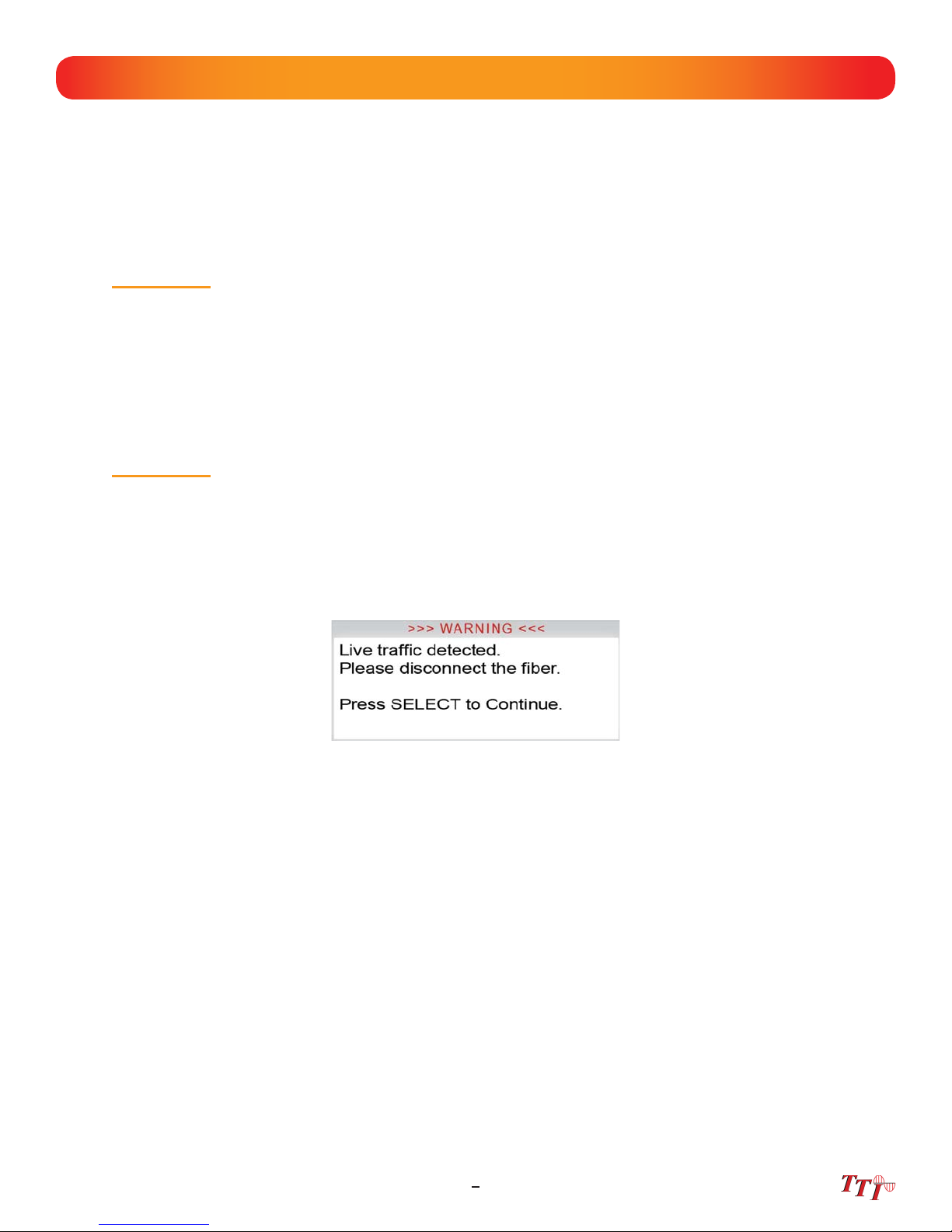
The OTDR is equipped with a protection circuit to avoid damage from live fiber connections The instrument will not operate properly with active fibers. Even with this protection, high power output from
EDFA’s or other equipment can damage detectors and should never be connected to the OTDR.
If a live fiber is connected to the OTDR and a scan is attempted, a warning dialog will be displayed as in
fig. 2.1. Immediately remove the live fiber from the OTDR and press select to continue testing.
Fig 2.1
3FTE-7000A User's Guide Rev A 5/2014
Page 9
Chapter 3 Quick Start Guide
Press to turn on the OTDR.
Use the directional buttons to highlight the OTDR icon and press to enter the OTDR function.
Connect the fi ber to the appropriate port. (SM or MM OTDR Optical Port)
Press to enter the Menu mode. The menu is displayed at the top of the screen. (To hide the
menu, press the menu button a second time.)
Use the right button to highlight the (wavelength) icon and use to cycle to the desired wave-
length.
If approximate fi ber length is unknown:
P
ress to have the OTDR start a test using the selected wavelength with the OTDR determining
the most appropriate range and pulse width. (Autotest will set the averaging time to 60sec.)
If approximate fi ber length is known:
S
et the Wavelength as above and further set the range, pulse width and averaging time.
Press to open the icon menu, use the left or right arrow to highlight the (range) and use
to cycle through the available ranges of 250m, 1km, 4km, 16km, 64km, 128km or 256km.
Use the left or right buttons to highlight the (pulse width) icon and use to cycle through the
available pulse widths of 5ns, 10ns, 30ns, 100ns, 300ns, 1us, 3us, 10us or 20us. (Not all pulse
widths will be available, only pulse widths appropriate for the selected range will be presented)
Press the left or right button to highlight the (average) icon and use to cycle to the averaging
times of Real-Time, 15 seconds, 1, 4, 16 or 40 minutes.
Press to exit the menu mode and hide the menu bar.
Press (Scan) to start a trace. Pressing the again will stop a trace.
FTE-7000A User's Guide Rev A 5/20144
Page 10
Chapter 3 Quick Start Guide
To operate the cursors, use the left and right buttons. Press the A/B button to toggle between A and B
as the active cursor.
To view the Fib-R-Map and event table, press , use the left and right buttons to highlight the
(schematic view) icon and press .
Note
Alternately, the touch screen may be used to view the trace with the event table or the Schematic view
by touching the tabs immediately below the grid scale. The OTDR tab displays the trace with the parameters listed and loss and distance measurements displayed. The Event tab displays the trace with
numbered events and an interactive event table, while the Schematic tab displays the trace with numbered events and an interactive schematic view of the data.
To save a trace, touch the button and use the left or right buttons to highlight the (fi le
storage) icon and press . Press , press and with save highlight press . Use the
touchscreen keyboard to enter the fi le name and touch save.
Note
The Quick Save icon may also be use to save the trace. Touching the Quick Save icon will store the
trace to the active project folder and use the last base fi le name entered.
5FTE-7000A User's Guide Rev A 5/2014
Page 11

Chapter 4 Introduction
Dear Valued Customer,
Thank you for choosing Terahertz Technologies Inc. for your fi ber optic testing
requirements. Our professional staff is available to answer any questions or provide
assistance that you require. We, at TTI Inc., strive to provide premier customer care and
technical support by providing timely responsiveness and training. We are proud of our
quality and high standards and assure you, our customer, the most user friendly and
affordable fi ber optic solutions to meet individual needs.
FTE-7000A User's Guide Rev A 5/20146
Page 12
Chapter 5 Inspection and Identifi cation
5.1 Inspection
Before shipment, this instrument was inspected and found to be in perfect working order and free of
defects.
The shipping carton contains the following:
1. OTDR with Protective boot and 4-AA NiMH batteries
2. Universal AC/DC charger with interchangeable mains
3. USB cable
4. Manual and CertSoft software on CD.
5. Set of interchangeable adapters, SC, ST and FC.
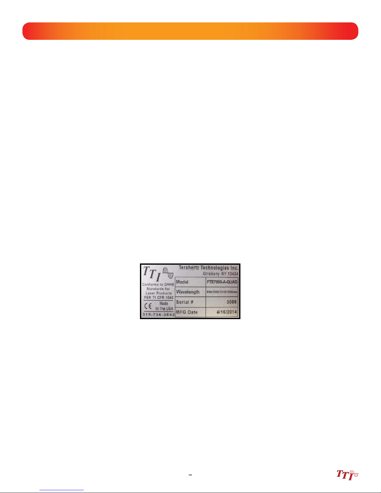
5.2 Identifi cation and Confi guration
The instrument’s Model/Part Number, Serial Number and Date of Manufacture are indicated on a
label located on the back of the unit. The instrument’s history is fi led at the factory by model/part
number and serial number. The unit's serial number is also located on the top plate just above the
USB Port.
Fig 5.1
7FTE-7000A User's Guide Rev A 5/2014
Page 13
Chapter 6 FTE-7000A Description
6.1 OTDR Physical Package/Description
Instrument Enclosure
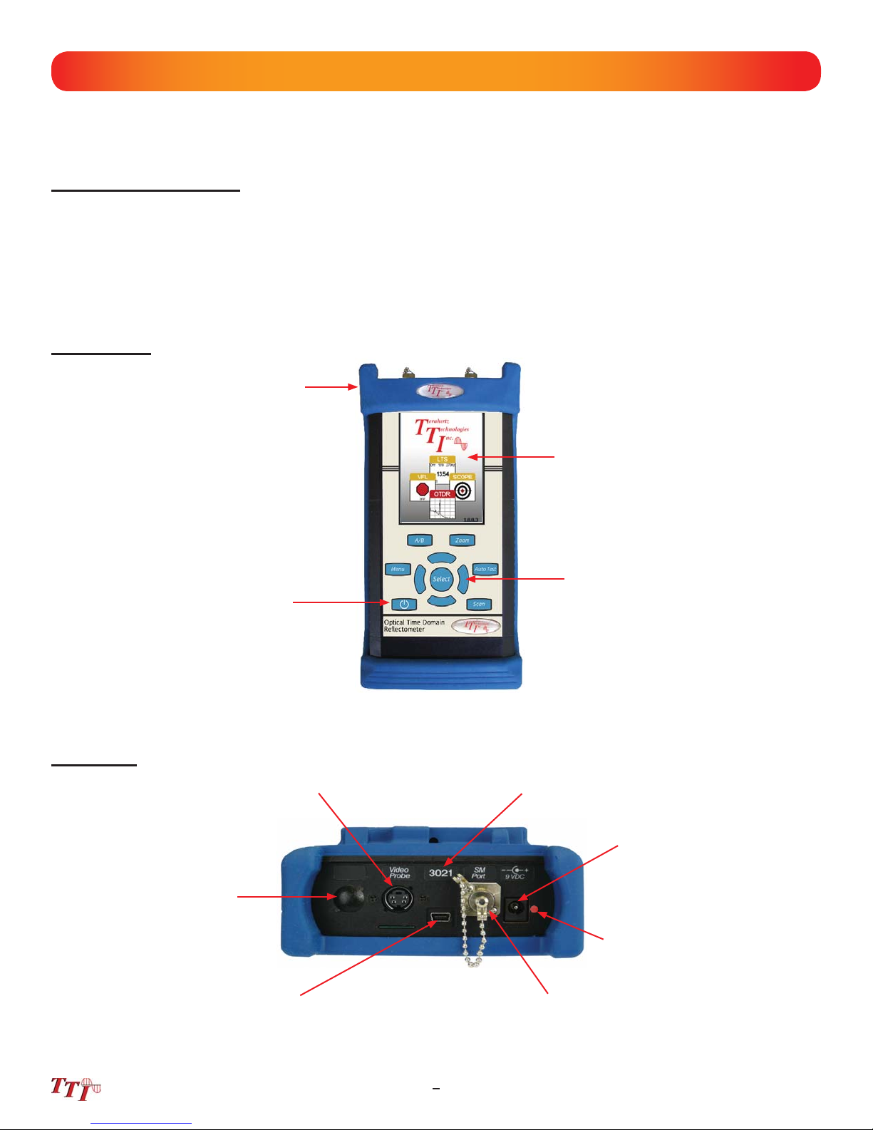
The ODM FTE-7000A is packaged in a rugged housing which is further protected with a rubberized
boot. Although the front panel is weather resistant, care must be taken to avoid liquids and contaminants around the fragile optical and electrical connectors, and the glass display. Use a mild cleaning
agent and soft damp cloth to clean up the panels and the outside case. See the maintenance section to clean the optical connector. NEVER open the instrument for cleaning. Return to the factory for
servicing if necessary.
Front Panel
Protective Rubber Boot
Color Touch Screen
Top panel
Position of Second
Optical Port for Quad
Wavelength OTDRs
Power Button
Video Probe Port
Key Pad
Fig 6.1
Unit Serial Number
Power Jack
Battery Charge
Indicator
USB Port
OTDR Port
Fig 6.2
FTE-7000A User's Guide Rev A 5/20148
Page 14
Chapter 6 FTE-7000A Description
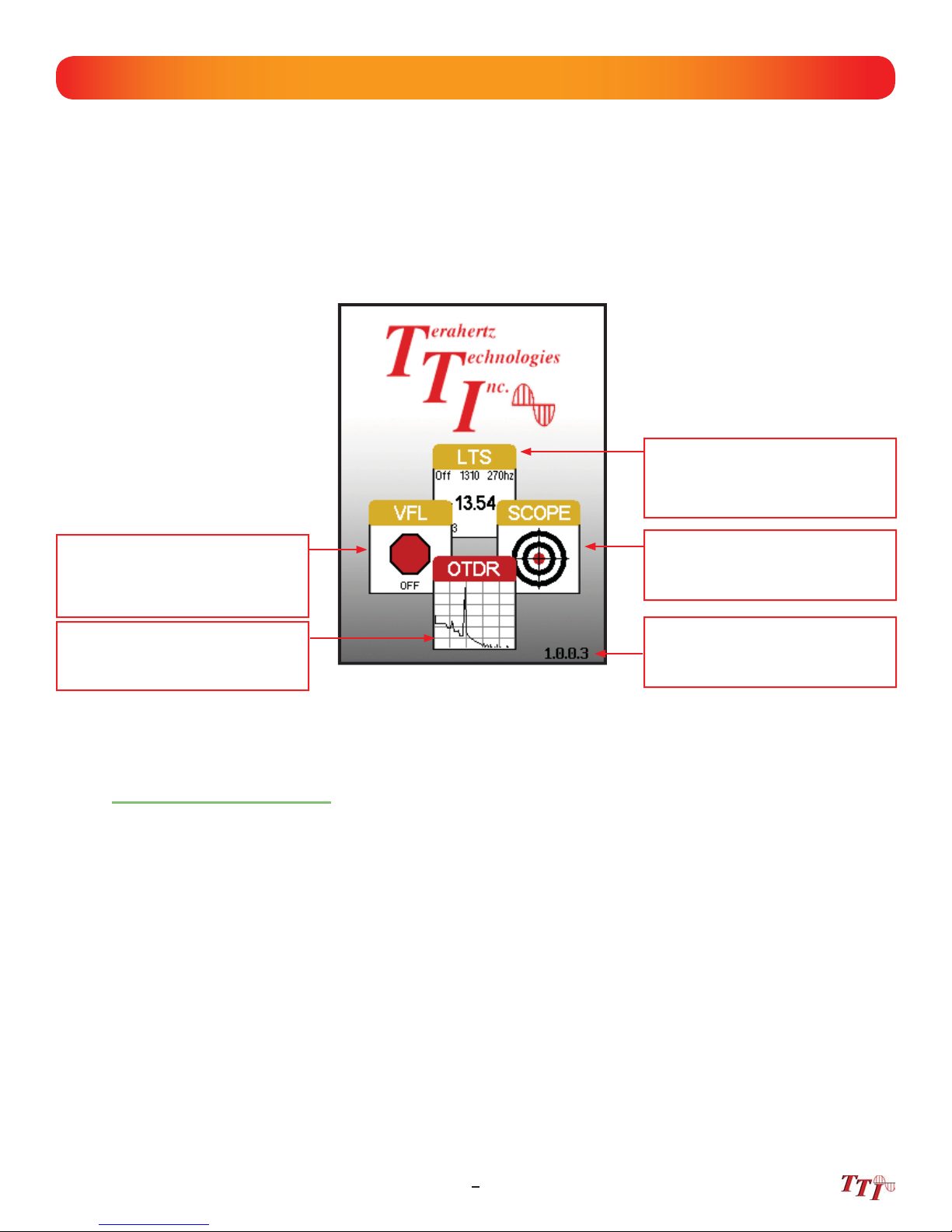
6.2 Home Screen Display
This unit is equipped with a 4” color TFT resistive touch display. All keyboard functions are also executable on
the touch screen.
Loss Test Set
If CW source is available, Select
this icon to access the CW mode of
the light source.
Visual Fault Locator
If unit is equipment with a VFL,
selecting this icon with will cycle
through the CW, Modulate and Off.
Video Scope Icon
Select this icon to open the video
scope function.
Optical Time Domain Icon
Select this icon to open the
OTDR function
Firmware Version
Fig 6.3
Touch Screen Tip
The home page icons are highlighted by using the left and right buttons, pressing the select button will
open the highlighted function. These icons may also be selected with the touch screen function.
6.3 Power Requirements
The FTE-7000A is equipped with a 100-240V-0.3A input and 9V, 0.67A center positive output universal AC/
DC battery charger. This charger is supplied with interchangeable mains for US, Great Britain, Europe and
Australia The unit is shipped with 4-AA NiMH batteries (2700mA hours). Fully charged battery pack will
typically enable approximately 4 of use. Fully discharged batteries require 6 - 8 hours of recharging.
9FTE-7000A User's Guide Rev A 5/2014
Page 15

Chapter 6 FTE-7000A Description
6.4 Battery Replacement
To replace the batteries, remove the OTDR from the protective boot by pulling the bottom of the boot down
and back allowing the bottom of the unit to be lift out. The battery door is located on the back side of the
unit. Replace the batteries with only high quality AA NiMH batteries. Spare battery packs are available with
a charging unit for extended battery operation. If you install NiMH batteries that are dead or less than 1 volt
each, charge these batteries for one (1) hour before using the OTDR. For proper maintenance, batteries require
a monthly recharge.
Warning
To Prevent Fire or Shock Hazard:
Do not install battery types other than those specifi ed by the manufacturer
Do not use the charger without the proper NiMH batteries installed
Do not expose the battery charger to rain or excessive moisture
Do not use the AC adapter when there are signs of damage to the enclosure or cord
Ensure that you are using the correct charger for the local line voltage
Do not use any other charger than the one provided with this instrument.
Failure to follow these caution statements could cause unsafe conditions for the operator and
equipment and may void the warranty.
FTE-7000A User's Guide Rev A 5/201410
Page 16

Chapter 7 OTDR Operation
7.1 Key Pad
Power button, turns the unit On and Off. (Hold for 1 second)
Scan button starts a scan or stops scan.
Fig 6.4
AutoTest button operates range fi nder trace mode. The Range Finder mode momentarily checks test conditions
and starts a scan at the wavelength selected by the user but allows the OTDR to determine the pulse width and
range parameters.
The Menu button displays and hides the icon menu at the top of the display. It will also back out of most menu
selected screens. In the project folder and fi le manager it opens the fi le/edit menu bar. When the menu is
displayed at the top of the screen, the focus of the LRUD buttons and the select buttons are on the icon menu
and no longer on the trace cursors.
Toggles between A and B as the active cursors.
Selects the Zoom level, each press increments through the levels of 1x, 2x, 4x, 8x, 16x and 32x.
In the menu mode, the select button actuates highlighted item.
While in the trace mode the directional buttons are used to move the cursors. In the Menu mode, the Left and
right buttons move between the icons. The up button hides the menu bar or moves cursor up in drop-down
menus and the down button opens drop-down menus or move cursor down while in a drop-down menu.
11FTE-7000A User's Guide Rev A 5/2014
Page 17

Chapter 7 OTDR Operation
7.2 Entering OTDR Function
Press the power button the to turn on the OTDR.
Use the LRUD button buttons to highlight the OTDR icon and press the select button to enter the
OTDR function.
7.3 Icon Defi nitions
Home Brings the user back to the home page
Quick Save
Quick Load Recalls the next fi le, chronologically in the current folder.
Project Folder Opens project management
File Manager Opens fi le management
Schematic View/Event Analysis Opens the Fib-R-Map and event analysis view
Settings Opens the parameters setting page.
Splice Zone Setting Turns on LSA/Splice markers
Help Opens the context sensitive help menu
Saves the current trace to the current folder, incremented
using last named fi le
Lambda (Wavelength) Cycles through available wavelengths
Pulse Width Cycles through available pulse widths
Range Cycles through available test ranges
Averaging Cycles through averaging times
Index of Refraction Opens the Index of Refraction entry screen
Fig 7.1
FTE-7000A User's Guide Rev A 5/201412
Page 18

Chapter 7 OTDR Operation
7.4 Main OTDR Screen
"A" Cursor with Position Data
Main Trace Screen
Distance Increment Indicators
"A-B" Cursor Status / Select
Displays the 2pt loss and distance
between the "A" and "B" cursors.
Touching anywhere in this area will
toggle between active cursors.
"B" Cursor with Position Data
Screen Tabs - Touching OTDR,
Events and Schematic tabs change
the bottom portion of the display
from parameters and measurement
data for the OTDR, the event table
for Events and the schematic view
for Schematic (See Fig 7.3)
Zoom Control
Displays the zoom level, and the
values in distance and dB per grid
division. Touch anywhere in the
area to cycle through the zoom
levels.
Test Parameters
Displays test parameters of wave-
length, averaging time, pulse width,
range and ORL. Touch the symbol
or value to cycle through the avail-
able settings.
Touch Screen Tip
Use the touch screen to snap cursors to a position by touching that point along the trace curve. The
active cursor will move directly to that point. For finer movement, touch active cursor and drag it to the
desired position. Finest movement can be accomplished with the LRUD buttons.
Touch Screen Tip
All the test parameters may be change by touching the value on the touch screen. A long touch in the
test parameter section of the screen will open the parameter settings page. A/B cursor, zoom, loss
method and scan may all be operated with the touch screen.
Loss Method
Displays splice loss, LSA splice
loss, dB per Km and ORL. Touch
anywhere in this area to cycle
through the loss methods.
Fig 7.2
Scan Button
Displays scan state / status and the
charge level of the batteries. Touch
anywhere in the area to start or stop
a scan.
13FTE-7000A User's Guide Rev A 5/2014
Page 19

Chapter 7 OTDR Operation
Trace Screen W/
Measurement Data
Trace Screen W/
Event Table
Trace Screen W/
Schematic view
Fig 7.3
There are three tabs on the main OTDR screen. OTDR, Events and Schematic. Use the OTDR tab
to view the trace with the loss and distance measurements. Use the Events tab to view an interactive
event table with the trace and numbered events or the Schematic tab to view an interactive schematic
view of the events with the trace and numbered events. Selecting an event in the event table or the
schematic view will snap the active cursor to that event.
7.5 OTDR Parameter Settings Screen
To access the parameter settings screen press the menu button, use the LRUD buttons to highlight the setting
icon and press the select button. An alternate manner to open this screen is to long touch the screen in the
test parameter section of the main OTDR screen.
Touch Screen Tip
All operations on this page are accessible via the touch screen. To change parameters or event
sensitivity, simply touch the desired value. To set thresholds and time, touch the setting and the block
will show yellow. The digits may now be adjusted with the up and down arrows.
Trace Parameter
Settings
Pass/Fail Thresholds
Settings
Event Table/Fib-R-Map
Sensitivity Settings
System Date/Time
Settings
Fig 7.4
FTE-7000A User's Guide Rev A 5/201414
Page 20

Chapter 7 OTDR Operation
Trace Parameter Settings
The cursor is the yellow highlighted area. (If the yellow cursor is on a value that is selected, that block will be
highlighted green) The blue values are the currently selected values. To move through this section, use the
Up/Down buttons to move between parameters and the Left/Right buttons to change parameter values.
There are two additional setting in this area that are not available on the main OTDR screen, distance unit and
pulse width unit.
Touch Screen Tip
When using the touch screen feature, only a single touch is required to set trace parameters.
Note
An arrow at the beginning or end of a list indicates additional setting are available. A black square at
either end indicated the end of the list.
Event Table/Fib-R-Map Sensitivity Settings
The cursor is the yellow highlighted area. (If the yellow cursor is on a value that is selected, that block will be
highlighted green) The blue values are the currently selected values. There are three levels of sensitivity for
the event table and Fib-R-Map. The lowest setting possible should be used to help fi lter out any events, that
may be caused by short pulse widths, but are not true perturbations in the optical signal
Pass/Fail Threshold Settings
There are four pass/fail thresholds that may be set. Use the LRUD buttons to move between threshold
categories, once a categories is highlighted, press select to change the focus of the LRUD buttons. Use the
up/down button to make changes to the highlighted digit and the left/right buttons to move the another digit.
Once the desired value is entered, press selected again. Continue until all thresholds settings have been
completed.
Date/Time Settings
Use the LRUD buttons to highlight the calendar month and press select. Use the left and right buttons to
change the month and press select. Use the LRUD buttons, highlight the date and press select.
Use the LRUD to buttons to highlight the clock and press select. Use the up/down buttons to make changes
to the highlighted digit and the left/right buttons to move the another digit. Once the desired time is entered,
press selected.
Exit Parameter Setting Screen
Press the menu button or touch Return to exit the parameter page.
15FTE-7000A User's Guide Rev A 5/2014
Page 21

Chapter 7 OTDR Operation
Warning
Before connecting a patch cord or fiber under test, be certain the fiber has no active optical sources or instruments connected to the other end. Skin or eye damage could result from other high power sources e.g. EDFAs,
or instrument damage could occur voiding the warranty.
Warning
Clean connector thoroughly prior to connection to the appropriate port of the OTDR. Failure to ensure the
connectors used with the OTDR are properly cleaned can result in poor launch conditions at the minimum or
damage to the optical interface that requires the unit be returned to the factory for repair.
7.6 Auto Test
Auto Test is a useful feature when the approximate length of the fi ber to be tested is unknown. To use the
AutoTest, only the IOR and Wavelength need to be set by the user.
Note
To assist in obtaining reliable, consistent measurements, the user should be aware of the Index of Refraction of their fiber. The proper Index of Refraction (IOR) will maximize the distance measurement accuracy. The IOR is proportional to the speed of light in glass compared to the speed of light in a vacuum
and can be calculated using the equation IOR = C (the speed of light in a vacuum) / V (the speed of
light in fiber). The IOR number can be obtained from the fiber or cable manufacturer or can be calculated with a known length of cable. IOR numbers generally fall around 1.468 SM, 1.486 MM. These are
the default values in the OTDR, but can be adjusted from 1.0 to 2.
default setting on the OTDR.
If this is unknown it is best to use the
Set IOR
It is necessary to have the Index of Refraction set as close as possible to the actual IOR of the fi ber. If this is
unknown it is best to use the default setting on the OTDR. To view the current IOR for a wavelength, open the
menu use the left/right button to highlight the IOR Icon. Press select and the IOR for the wavelength that is the
active will be displayed. To change the IOR, use the on screen QWERTY keyboard to enter the new value and
touch save. Each wavelength stores an independent IOR.
Set Wavelength
To select the wavelength, press the menu button to display the menu at the top of the display. Use the LRUD
buttons to highlight the Lambda (Wavelength) icon, press select to cycle through the available wavelengths
and press the menu button again to hide the menu. Use only the single wavelength settings for the Autotest
feature.
Note
The wavelength for dual MM OTDR are 850nm, 1300nm and 850/1300nm, for SM OTDR they are
1310nm, 1550nm and 1310/1550nm. For the Quad wavelength OTDR, they are 850, 1300, 850/1300,
1310, 1550 and 1310/1550nm. The 850/1300nm and 1310/1550nm settings are for Construction Mode
operation where the OTDR will test both wavelengths in one operation. Construction mode is covered
in section 7.8 of this guide.
Start Auto Test
Press the AutoTest button and the unit will set the average time to short, the appropriate pulse width and range
parameters for the fi ber under test.
FTE-7000A User's Guide Rev A 5/201416
Page 22

Chapter 7 OTDR Operation
Warning
Before connecting a patch cord or fiber under test, be certain the fiber has no active optical sources or instruments connected to the other end. Skin or eye damage could result from other high power sources e.g. EDFAs,
or instrument damage could occur voiding the warranty.
Warning
Clean connector thoroughly prior to connection to the appropriate port of the OTDR. Failure to ensure the
connectors used with the OTDR are properly cleaned can result in poor launch conditions at the minimum or
damage to the optical interface that requires the unit be returned to the factory for repair.
7.7 Manual/Expert Mode
Note
To assist in obtaining reliable, consistent measurements, the user should be aware of the Index of Refraction of their fiber. The proper Index of Refraction (IOR) will maximize the distance measurement accuracy. The IOR is proportional to the speed of light in glass compared to the speed of light in a vacuum
and can be calculated using the equation IOR = C (the speed of light in a vacuum) / V (the speed of
light in fiber). The IOR number can be obtained from the fiber or cable manufacturer or can be calculated with a known length of cable. IOR numbers generally fall around 1.468 SM, 1.486 MM. These are
the default values in the OTDR, but can be adjusted from 1.0 to 2.
default setting on the OTDR.
If this is unknown it is best to use the
Set IOR
It is necessary to have the Index of Refraction set as close as possible to the actual IOR of the fi ber. If this is
unknown it is best to use the default setting on the OTDR. To view the current IOR for a wavelength, open the
menu use the left/right button to highlight the IOR Icon. Press select and the IOR for the wavelength that is the
active will be displayed. To change the IOR, use the on screen QWERTY keyboard to enter the new value and
touch save. Each wavelength stores an independent IOR.
Touch Screen Tip
All the test parameters may be change by touching the value on the screen to the right of the icon. A
long touch in the test parameter section of the screen will open the parameter settings page.
Set Wavelength
To select the wavelength, press the menu button to display the menu at the top of the display. Use the LRUD
buttons to highlight the Lambda (Wavelength) icon, press select to cycle through the available wavelengths and
press the menu button again to hide the menu.
17FTE-7000A User's Guide Rev A 5/2014
Page 23

Chapter 7 OTDR Operation
Note
When setting the range and pulse width, it is necessary to keep in mind that it may not be beneficial to
use certain pulse widths with some ranges. For this reason not all pulse widths are available for use
with all rangers. The chart below the pulse widths that are available with each range.
Pulse Width
5ns 10ns 30ns 100ns 300ns 1μ 3μ 10μ 20μ
250m
1km
4km
16km
Range
64km
128km
256km
Set Range
To set the range, press the menu button and use the LRUD buttons to highlight the range icon. Use the select
button to cycled to the desired range.
Set Pulse Width
To set the pulse width press the menu button and use the LRUD buttons to highlight the pulse width icon. Use
the select button to cycled to the desired pulse width
Set Averaging Time
To set the averaging time press the menu button and use the LRUD buttons to highlight the averaging icon.
Use the select button to cycle through the averaging times of RT (Real Time), 15, or 60 seconds, 2 or 4, 8 or
20 minutes.
Touch Screen Tip
The above setting may be made with the touch screen by simply touching the appropriate icon in the
icon menu to cycle through the available settings. Also the parameter settings page may be opened
and all settings may be made on this screen.
Scan
Once all the proper settings have been entered, press the Scan button to take the trace. To stop the trace
press the scan button again.
FTE-7000A User's Guide Rev A 5/201418
Page 24

Chapter 7 OTDR Operation
7.8 Construction Mode
Construction Mode is useful when a large number of fi bers need to be tested with the same settings at multiple
wavelengths. This operation mode test a fi ber at two wavelengths, saves the traces and displays them in dual
trace mode.
Open or Create a Project Folder
Open project management and highlight the project folder with the proper parameters for the test and where
the fi les should be stored. If a new project needs to be established do so using the information from Chapter 8
of this guide.
Set Base File Name
Once the fi le management folder has been opened the fi les folder for that project will be displayed. A base
fi le name for the test should be established. Press the menu button to open the fi le management menu, with
the fi le tab highlighted, press the select button or the down button to open the drop-down menu. With save
highlighted press select. Use the QWERTY to enter a base fi le name.
When testing in construction mode, fi les will be save in numeric order. For example, if the base fi le name of
romecity were entered, the fi rst test in construction mode (If the test were at 1310/1550nm) would be a test
at 1310nm with a name of romecity1 and the second test would be the same fi ber at 1550nm with a name of
romecity2. The next test would be romecity3 and romecity4.
Once the base fi le name is set, exit the fi le manager by pressing the menu button, pressing select on the fi le
tab, using the down button to highlight exit and pressing select.
Set the Wavelengths
On the main trace screen in the OTDR tab the wavelength settings are accessible. There are wavelength
settings available here that are not in the parameters setting screen. Dual wavelength units will have one extra
setting of a combination of the two wavelengths. For example, if the OTDR is a 1310/1550nm dual wavelength
unit, there will be three available selection here. 1310, 1550, and 13/15. The 13/15 is used for constructions
mode. This needs to be selected anytime construction mode is to be used. Quad wavelength units will have
850, 1300, 1310, 1550, 85/13 and 13/15, where either 85/13 or 13/15 may be use for construction mode testing.
Use the touch screen to cycle through these wavelength settings.
19FTE-7000A User's Guide Rev A 5/2014
Page 25

Start A Test
To start the test connect the fi ber to be tested to the proper OTDR port and press the scan button.
The OTDR will test the fi ber at the shorter wavelength, display the trace and save the fi le. It will then test the
fi ber the longer wavelength, The longer wavelength will become the primary trace and the two test will be
displayed in dual trace mode.
When the test is complete for the fi rst fi ber, remove the connector from the OTDR, insert the next fi ber to be
tested and press the scan button. Continue until all test are complete.
Note
Macrobend tests are automatically conduct with construction mode. Simply enter the Events tab on the
OTDR screen or open the event analysis screen through the icon menu. For information about
marobend analysis, please refer to section 7.11 of this guide.
Exiting Construction Mode
To exit construction mode, set the wavelength on the trace screen to a single wavelength and start a scan.
FTE-7000A User's Guide Rev A 5/201420
Page 26

Chapter 7 OTDR Operation
7.8 Trace Analysis
Unit of Measure
The distance unit of measure may be either displayed in Kilometer (Km), Kilo feet (Kf) or Miles (Mi). To set the
unit of measure, press the menu button, use the LRUD buttons to highlight the settings icon and press select to
open the parameter screen. Use the down button to move the cursor to the D.Unit line in the parameter menu,
and use the left or right button to highlight the desired unit of measure and press select. Press the menu
button or touch Return to exit the parameter settings page.
Note
When in the Kilo feet (Kf) mode, the distance measurements are displayed in feet for the 820 foot and
the 3.2 Kf ranges. All longer ranges have the distance measurements displayed in Kf.
Zoom
There are six zoom levels, 1x, 2x, 4x, 8x,16x and 32X. To change the zoom level, press the zoom button on
the keypad. This will cycle through the six levels. When viewing the trace at a zoom level other than 1x, the
active cursor is centered on the trace display and when the cursors are moved, the trace moves and the cursor
will remain centered.
Cursor Movement
The active cursor is displayed as a solid line and the non-active cursor as a dashed line. Pressing the A/B
button on the keypad toggles between the two cursors as the active cursor. The cursors are moved using the
left and right buttons.
Touch Screen Tip
Use the touch screen to snap cursors to a position by touching that point along the trace curve. The
active cursor will move directly to that point. For finer movement, touch active cursor and drag it to the
desired position. the finest movement can be accomplished with the left and right buttons.
7.9 Loss Measurements
2 Point loss
2 Point loss measurements take into account the difference in vertical height between where the A and B
cursors cross the fi ber trace to determine loss. This information is located on the main OTDR screen in the A-B
section of the trace information as shown in Fig. 7.2. This is a quick method of checking the loss between any
two points on a fi ber optic link.
dB/km
The dB/Km (dB/Kft or dB/Mi) loss method takes the 2 Point loss in dB and divides by the distance between the
cursors in Km (Kilometers), Kf (Kilofeet) or Mi (Miles). For accurate dB/.... loss measurements, the two cursors
must be on level backscatter points at least 100m apart (NA will show for distances that are too short).
21FTE-7000A User's Guide Rev A 5/2014
Page 27

Chapter 7 OTDR Operation
Optical Return Loss
This Optical Return Loss (ORL) is separate from the event ORL (Refl ectance) that is displayed in the
event analysis under the TYPE header for an individual event. The measurement displayed in the loss
measurement area of the main OTDR screen and in the E (End of Fiber) row in the TYPE column is an optical
return loss based on the entire link. It is the total accumulated light refl ected back to the source along the
telecommunication link.
Basic Splice Loss
Splice Loss method is meant to be used in noisy environments when it is diffi cult to attain an LSA area that
lays fl at on the back scatter before and after the cursor. This method takes an average of the selected points
before and after the active cursor and uses this average to make a good estimation of the event loss. This is an
estimation but this method may be more accurate than LSA Splice Loss method in noisy environments.
When using the splice loss It is necessary to set these areas in clear backscatter (areas that do not consist of
other events) to acquire the most accurate measurements. For accurate measurements, these areas can not
include other events such as refl ective or splice events. Set a cursor at the beginning of an event and set splice
loss measurement areas as directed below and as shown in Fig. 7.6 for accurate splice loss measurements.
Splice loss measurement areas will follow the undulations of the back scatter line unlike LSA areas.
Least Squares Approximation (LSA)
Least Squares Approximation (LSA) Splice loss method gives the user a visual aid in setting splice loss areas.
This method can be more accurate by affording the ability to see the slope of the splice loss areas, however:
it can also supply a reading with greater error if not used properly. The splice loss lines must be set to overlay
the backscatter of a trace without over lapping any other events. Unlike basic splice lose, LSA measurement
areas are drawn as straight lines without regard to the undulations of the back scatter
7.10 Loss Measurement Settings
Touch Screen Tip
The loss measurement/LSA areas may only be set with the key pad. Use the menu to enter the LSA
settings function, but once there, use the key pay to adjust the areas as described. It is best to be
zoomed in on an event to best set the loss measurement areas.
Setting Splice Loss Measurement Areas
To set the basic splice loss measurement/ LSA ares, the OTDR must be in Splice AVG or Splice LSA mode.
To adjust the splice loss areas around the cursors, press the menu button, highlight the LSA icon and press
select. The splice lose position indicator will be displayed at splice loss position number 1 as indicated in Fig.
7.6. Use the left and right buttons to adjust the loss measurement area. Press the select button to move the
splice lose position indicator to the position number 2, set the area and continue with positions 3 and 4 in the
same manner. Press select when done with position number 4 to hide the splice lose position indicator and
reset the focus of the keyboard back to the cursors. Press the menu button at any time to escape the splice
lose settings sequence.
Note
It is necessary to set these areas in clear backscatter to acquire the most accurate measurements, they
must not include other events.
FTE-7000A User's Guide Rev A 5/201422
Page 28

Chapter 7 OTDR Operation
Splice Loss Adjustment Areas
Active Splice
Zone Cursor
LSA Splice Loss
Measurement Areas
Basic Splice Loss
Measurement Areas
Active Splice
Zone Cursor
LSA Splice Loss
Measurements
Splice Loss Adjustment Positions
Splice Loss Position
#1
Splice Loss Position
#2
Fig 7.5
Fig 7.6
Basic Splice Loss
Measurements
Splice Loss Position
#3
Splice Loss Position
#4
23FTE-7000A User's Guide Rev A 5/2014
Page 29

Chapter 7 OTDR Operation
LSA Examples
LSA Set Too Early:
Fig 7.7
LSA Set Too Late:
The LSA area and cursor are
set too early. The right most
green LSA indicator line is not
over laying the back scatter of
the trace properly
Proper LSA Setting:
The LSA area and cursor are
set too late. The left most green
LSA indicator line is not over
laying the back scatter of the
trace
Fig 7.8
The LSA area and cursor are set
properly. The green LSA indicator line is over laying the back
scatter of the trace properly.
Fig 7.9
FTE-7000A User's Guide Rev A 5/201424
Page 30

Chapter 7 OTDR Operation
7.11 Event Analysis
NOTE:
When using the event table and the Fib-R-Map, it is necessary to keep in mind that event analysis
provides approximate loss and distance measurements to quickly assist in network evaluation.
Automatic detection results are not guaranteed and have their limits, possibly causing
erroneous readings or detection failure. User interaction by interfacing with the trace display is
recommended for fi nal qualitative and quantitative analysis.
Enter Event Analysis
To enter event analysis, press the menu button and use the left / right buttons to highlight the event analysis
icon and press select.
NOTE:
All the entries on the parameter screen are operational with the touch screen. To exit the parameter
screen with touch screen function, touch the Return button.
Threshold Settings
There are four threshold settings, EOF, Loss, ORL and Link. (See Fig 7.4) The EOF is not a Pass/Fail
threshold, it is used to set a loss value to determine the end of fi ber. IF the EOF threshold is set for 3dB, then
the fi rst event that has a loss of 3dB or greater will be deemed the EOF.
To change the threshold settings, press the Menu button, use the left/right buttons to highlight the settings
icon and press select. The cursor is the yellow highlighted area. (If the yellow cursor is on a value that is the
current selection, that block will be highlighted green.) The setting highlighted in blue is the current setting.
Use the LRUD buttons to highlight the desired threshold category and press the select button. Use the up/
down buttons to set the digit, and use the left/right buttons to move to the next or previous digit. Once the
desired setting is entered, press the select button. Use the LRUD buttons to move to the next setting until all
thresholds have been set as desired. To exit the parameter screen, press the menu button.
Splice, ORL and Link are all thresholds for Pass/Fail purposes.
NOTE:
Thresholds are "pass thresholds", a value entered as a threshold is a passing value.
Examples of these settings are as follows:
Splice: If a 1.00dB splice loss is acceptable, set the threshold to 1.00. If a splice loss of 1.00 is the fail
point, set the threshold to 0.99
ORL: If a -50dB refl ectance is acceptable, set the threshold to 50. If -50dB is the fail point, set the
threshold to 50.5.
Link: If a 20dB, link loss is acceptable, set the threshold to 20. If 20db link loss is the fail point, set
the threshold to 19.5.
25FTE-7000A User's Guide Rev A 5/2014
Page 31

Chapter 7 OTDR Operation
Sensitivity Settings
There are three levels of sensitivity for the event table and Fib-R-Map. (See Fig 7.4) To change the event
sensitivity, press the Menu button, use the left/right buttons to highlight the settings icon and press select. The
cursor is the yellow highlighted area. (If the yellow cursor is on a value that is the current selection, that block
will be highlighted green.) The setting highlighted in blue is the current setting. Use the LRUD buttons to
highlight the desired setting and press select. To exit the parameter screen, press the menu button.
The lowest setting possible should be used to help fi lter out any false events that may be caused by short pulse
widths, but are not true perturbations in the optical signal. High sensitivity presents events with loss down to
approximately 0.1dB, Medium (Md) with events down to approximately 0.2dB and Low (Lo) for event down to
about 0.5dB. Longer pulse widths, and averaging help to lower the number of false events. Highest sensitivity
settings should only be used for traces with high signal level, low noise, long pulse width and long average.
Macrobend Analysis
Macrobend analysis is performed with the dual trace operation and displayed in the event table. The traces
to be compared must have been performed at the same range and the primary trace must be of the longer
wavelength.
To conduct a macrobend analysis, open the fi le manager as described in chapter 9. Highlight the fi rst trace to
be loaded (the trace of the longer wavelength) and select to open. Open the fi le manager again and highlight
the trace to be compared (the trace of the short wavelength), open the drop-down menu under the fi le tab and
touch dual or use the up or down buttons to highlight dual and press select. Open the event analysis screen to
check for macrobends. If and event on the longer wavelength trace has 0.25db or greater loss than the same
event on the shorter wavelength trace, a macrobend event will be generated on the event table, identifi ed by
a Macro label in the Type column. This event will immediately follow the event it is related to. For example:
If event number one was 5 dB at 1550nm and .5 db at 1310nm, the second event will be blank for location,
+4.5dB for splice, blank for 2point and DB/KM. The type fi eld will be listed as Macro.
To exit dual trace and macrobend analysis, simple start a new scan.
Event Analysis Screen
Event Table
Fib-R-Map
Schematic View
Trace Parameters
Event Map
Fig 7.10
FTE-7000A User's Guide Rev A 5/201426
Page 32

Chapter 7 OTDR Operation
Fib-R-Map
Loss Between
Events
Event Location
Event Loss in dB
Event Map
Event Number
Event Type and
Refl ectance Value
System ORL
Link Data
Fig 7.11
Note
The Link is the last item in the schematic view. It is labeled E in the event number position. The loss
value just prior to this item is the Link Loss and the Event location above the item is the same as the
location of the event deemed the EOF.
Event Table
Pass/Fail
Event Number
EOF Data
Note
Information in the red outlined area is for individual events. Information in the blue outlined area is for
the fiber link.
Event Location Event Loss in dB
E
EOF Location Link Loss
Loss Between
Events
Fig 7.12
dB Per/Km
Between Events
Event Type or
Refl ectance Value
System ORL
dB Per/Km
Between Events
27FTE-7000A User's Guide Rev A 5/2014
Page 33

Chapter 7 OTDR Operation
Table Definitions
# Event Number:
Indicates the event in sequence, where the higher the number the further distance from the OTDR the event
occurs. “E” (End) which is always displayed in the bottom row is the event determined to be the End of Fiber
(EOF).
P:
Pass/Fail, if any one of the thresholds are not met for and event, the P/F column will display a red F. The
parameter that failed will also be displayed in red. If all the parameters are met, this column will display a green
P. The Pass/Fail threshold for the last event labeled "E" is the loss displayed in the 2POINT column, the link
loss threshold.
Km or KF or MI:
Event Location, Km for Kilometer or KF if unit of measure is Kilo-feet MI for mile. This is the distance/location
that the event occurs along the fi ber link.
Splice:
Event Loss, is the splice loss (event loss) of the numbered event. (A positive number is the amount of loss and
a negative number indicates a gain normally due to mismatched index of refraction.) This is a settable threshold
for the Pass/Fail feature. The "E" event will display LINK as this is not an event that would have meaning. The
event that is deemed the EOF will normally display a large loss as this loss will be greater than the threshold
set to determine the end of the fi ber.
2POINT:
2 Point Loss is the loss measured from the end of the dead zone of the previous event to the beginning of
current event. The value in the "E" line of the table for this column is the link loss. The loss from the beginning
of the trace to the event determined to be the EOF. This is the value used to determine if the fi ber link passes
or fails it's loss threshold.
dB/Km:
dB per Kilometer if in KM and DB/KF if in Kilo-Feet and DB/MI if in mile unit of measure. This is the
calculated loss per Km, Kf or Mi from the end of the dead zone of the previous event to the beginning of the
current event. The value in the "E" line of the table for this column is the dB Per/KM, Kf or Mi for the total link.
TYPE:
Event Type is the type of event or the ORL measurement. If the event has no refl ection, “splc” will be displayed
and if the event contains a refl ection, the event refl ectance value will be displayed. For the last event which is
labeled "E" in the # column, the value displayed is the system ORL.
FTE-7000A User's Guide Rev A 5/201428
Page 34

Chapter 8 Project Management
8.1 Project Management Description
Project Management allows the user to save a set of parameters to be recalled for use at a later time. It also
incorporates the fi le management system to save traces to the active project folder. When the OTDR is turned
on, the default project is [NONE]. If an existing project is not open or a new one not set, all traces will be saved
to the [NONE] folder.
Note
In project and file management screens, the down button opens drop-down menus when and moves
the cursor down through the drop-down menus and the up button hides the menu or moves the cursor
up through the drop-down menus.
Note
It is necessary to create the project prior to taking a trace as the file will not be available to save after
going through the project creation sequence.
Project Management Screen
Project Folder
List
Project
Details/Properties
Fig 8.1
Project Management Menu
The menu for project management may be operated with the touch screen, however, this manual describes
the manner of operation with the keypad. To open the menu press the menu button. There are four tabs
available, File, Edit, View and Help. Use the left or right buttons to move to a desired tab and use the select or
the down button to open the drop-down menus. Pressing the menu button again or the up button will hide the
operations menu.
Fig 8.2
Touch Screen Tip
The menu may be pulled down with the stylus the same as the menu on the main trace screen. Once
the file menu is open, it is fully operable with the touch screen function.
29FTE-7000A User's Guide Rev A 5/2014
Page 35

Chapter 8 Project Management
Project Management File Tab To open the drop down menu under fi le, with fi le tab highlighted, press
select or the down button. Use the down or up buttons to move through the drop down menu and select to
choose and operation. Selecting new will open a new project folder using the current parameter settings.
Open will open the highlighted project, dual is not operational in the project management and therefore greyed
out, delete permanently removes the highlighted project. (The delete button must be held for at least one
second to remove projects.) Once delete is selected, the project and all fi les associated with that project are
deleted. Use exit to leave the project manager and return to the trace screen.
Fig 8.3
NOTE:
Once a project is established the settings cannot be permanently changed. They may be changed
Temporarily, but the original setting will be defaulted every time the project is opened.
Project Management Edit Tab
To open the drop-down the menu under edit, with the edit tab highlighted, press select or the down button. Use
the down or up buttons to move through the drop down menu and press select to choose an operation. Upload
is used to transfer fi les to the CertSoft software. Rename allows the highlighted folder name to be modifi ed
while maintaining all settings and associated fi les. Properties allows the user to edit the properties displayed
at the bottom of the project window.
Fig 8.4
Project Management View and Help Tabs
View offers the user the opportunity to move to the fi le manager from the projects page. With view highlighted,
press select or the down button to open the drop-down menu, with the fi les tab highlighted, press select to
move to the fi le management page. For onboard help pages, highlight the help tab and press select.
Fig 8.5
FTE-7000A User's Guide Rev A 5/201430
Page 36

Chapter 8 Project Management
8.2 Project Management Operation
Create a New Project
The parameters that are stored for a project are; range, pulse width, average, wavelength, distance units, pulse
width units, event sensitivity and the thresholds. To create a new project, press menu, select the settings icon,
set the parameters as required, when all setting are established, use the arrow button to highlight the return
button or touch return at any time while in the settings screen. Press the menu button, highlight the project
folder icon and press select. With the fi le tab highlighted, press select or the down button to open the drop
down menu. Use the down or up buttons to highlight new and press select again. Use the on screen QWERTY
keyboard to name the folder and touch save. The folder names are limited to 16 characters.
To enter details about the project, use the up and down buttons to highlight the project that was just created
and press the menu button. Use the left or right button to highlight the edit tab, use the down button to
highlight properties and press select. Use the up and down buttons to select the desired fi eld to be entered
or modifi ed and press select. Use the QWERTY keyboard to enter the information and touch save when
complete. Up to 24 characters may be entered for these fi elds. To exit the project screen, press menu, press
select, use the down button to highlight exit and press select again.
Open an Existing Project
To open a project, press the menu button, highlight the project folder and press select. Use the up or down
buttons to highlight the desires project folder and press select. This will open the fi le management screen
listing all the fi les previously stored in this project. All saved traces will now be stored to this project ,until a new
project is created or another project is opened.
Delete a Project
To delete a project, with the project to be deleted highlighted, open the fi le drop down menu, highlight delete
and press and hold select. Ensure the proper project is selected as once deleted, the folder and fi les cannot be
recalled.
NOTE:
Delete must be held for approximately 1 second to complete the delete function.
Upload a Folder to CertSoft
To upload a folder and all it's associated fi les from the OTDR to the computer, open the CertSoft software and
ensure the OTDR is connected to the computer with the USB cable.
NOTE:
The two plugs in the top right corner of the OpTrace screen should show as connected and green.
Highlight the project to be uploaded, press menu to open fi le manager menu, use the right button to highlight
edit tab, press select or the down button to open the drop down menu and with upload highlighted, press
select. The folder with all fi les will be uploaded to the target folder selected on the computer.
31FTE-7000A User's Guide Rev A 5/2014
Page 37

Chapter 8 Project Management
Rename a Project
To rename a project, have the project to be renamed highlighted, press menu, to open the project management
menu. Use the left and right buttons to highlight edit tab and press select or the down button to open the dropdown menu. Use the down button to highlight rename and press select. The project name will be displayed
with the onboard QWERTY keyboard. Use the keyboard to rename the project and touch save.
Modify Properties
To modify the properties, have the project to modifi ed highlighted. Press menu, highlight edit/properties
and press select. The project properties will be displayed, use the up/down buttons to highlight the fi eld to
be changed, use the onboard QWERTY keyboard to make the change and touch save. Continue with the
changes needed, when compete highlight close and press select.
Use the left and right buttons to highlight edit tab and press select or the down button to open the drop-down
menu. Use the down button to highlight properties and press select. The properties list will be display, use the
up or down buttons to highlight the property to be modifi ed and press select. The QWERTY keyboard will be
displayed with the property information. Press save when done with the change. Continue with the changes
needed, when compete highlight close and press select.
Temporary Modification of Parameters
Test parameters may be temporarily changed by selecting new settings, such as wavelength, average time,
pulse width, and range directly on the main OTDR screen with the touch screen capabilities or open the
parameter settings screen, set the new parameter and save. All subsequent test will use the new settings until
the original settings are returned or the folder is reopened resetting the project parameters. To make temporary
changes to event sensitivity or thresholds, open the parameters settings page.
Exit Project Management
To exit the project management, press menu, use the left or right buttons to highlight the fi le tab, press select
or the down button to open the drop down menu. Use the down button to highlight Exit and press select.
FTE-7000A User's Guide Rev A 5/201432
Page 38

Chapter 9 File Management
9.1 File management Description
File Management is use to save and recall traces. It operates in conjunction with the projects manager in that
if a project folder is open, the fi les saved to and listed in the fi le manager are associated with the open project.
When the OTDR is turned on, the default folder is [NONE], therefore, any fi les save without opening a project
will be save to the [NONE] folder. Any fi les saved in the scope function will also be associated with the open
folder.
File Management Screen
Project Folder
Being Viewed
OTDR Traces
Files List
Trace
Details/Properties
Fig 9.1
File Management File Menu
The menu for fi le management may be operated with the touch screen, however, this manual describes the
manner of operation with the keypad. To open the fi le management menu press the menu button.
Fig 9.2
Touch Screen Tip
The file menu may be pulled down with the stylus the same as the menu on the main trace screen.
Once the file menu is open, it is fully operable with the touch screen function.
33FTE-7000A User's Guide Rev A 5/2014
Page 39

Chapter 9 File Management
File Management File Drop Down Menu
To open the drop down menu under fi le, with fi le highlighted, press select or press the down button. Use the
down or up arrow to move through the drop down menu and press select to open the highlighted operation.
The operations are Save, Open, Dual, Delete and Exit. Save stores the current trace, Open displays the trace
that is currently highlighted, Dual opens a secondary trace, Delete permanently removes a fi le and Exit closes
the fi le management screen.
Fig 9.3
File Management Edit Drop Down Menu
To open the drop down menu under edit, with edit highlighted, press select or press the down button. Use the
down or up arrow to move through the drop down menu and press select to choose a highlighted operation.
Upload is used to transfer the highlighted fi le to the CertSoft software. Rename allows the highlighted fi le
name to be modifi ed. Properties is grayed out and not accessible from this location.
Fig 9.4
File Management View and Help Menu
View offers the user the opportunity to move to the projects management page from the fi le management page.
With view highlighted, press select or the down arrow to drop down the view tab and press select to move to
the fi le management page. For onboard help pages, highlight the help tab and press select.
Fig 9.5
9.2 File management Operation
Save a Trace File
To save a trace, press menu, highlight the fi le manager icon and press select. Press select or the down button
to open the drop down menu and with save highlighted, press select again. The fi le naming window will open
and the onboard QWERTY key board will be available. Use the touch keyboard to name the fi le and touch
save. The fi le names are limited to 16 characters. This method should be used to set the base fi le name for a
group of traces. These fi le names are save exactly as entered. To save fi les with a chronologically numbered
suffi x, use the quick save. Quick Save uses the last enter base fi le name.
FTE-7000A User's Guide Rev A 5/201434
Page 40

Chapter 9 File Management
Open/View a Trace
To open a trace, press the menu button, highlight the fi le folder and press select. Use the up or down buttons
to highlight the trace to be viewed and press select.
Dual Trace Mode
Dual trace mode may be used to view and compare two traces. Both traces must be of the same range
setting. To utilize dual trace feature, fi rst open the primary trace as you would a normally, by highlighting the
trace in fi le management, pressing menu to open the fi le management menu, with fi le highlighted, open the
drop-down menu use the down button to highlight dual and press select. The trace opened using the dual
feature is the secondary trace and all information displayed is that of the primary trace. To exit the dual trace
mode, start a scan with the scan button.
Delete a File
To delete a fi le, with the fi le to be deleted highlighted, press menu or the down button to open the fi le drop
down menu, use the down or up buttons highlight delete and press select for at least one second. Ensure the
proper fi le is selected as once deleted, the fi le cannot be recalled.
NOTE:
Delete must be held for approximately 1 second to complete the delete function.
Upload a Trace to CertSoft
To upload a trace from the OTDR to the computer, Open the CertSoft software and ensure the OTDR is
connected to the computer with the USB cable.
NOTE:
The two plugs in the top right corner of the OpTrace screen should show as connected and green.
Highlight the fi le to be uploaded, press menu to open fi le manager menu, use the right button to highlight
the edit tab, press select or the down button to open the drop down menu and with upload highlighted, press
select. The fi le will be uploaded to the target folder on the computer .
Rename a Trace File
To rename a trace fi le, have the fi le to be renamed highlighted. Press menu, use the left or right button
to highlight edit, press select, or the down button to open the drop-down menu, press the down button to
highlight rename and press select. The fi le name will be displayed with the onboard QWERTY keyboard. Use
the keyboard to rename the project and touch save.
Exit File Management
To exit the fi le management, press menu, use the left or right buttons to highlight the fi le tab, press select or the
down button to open the drop down menu. Use the down button to highlight Exit and press select.
35FTE-7000A User's Guide Rev A 5/2014
Page 41

Chapter 10 Video Scope
10.1 Video Scope Display
To operate the video scope, from the home screen, highlight the Scope icon and press the select button. If
a probe is not connected already, connect the VIS300 video probe to the video probe port on the top of the
OTDR.
10.2 Video Scope Display
Project Folder
Home Icon
250um Ring
120um Ring
(Yellow)
Contaminant Scale
Pass/Fail Grading
Ring Overlay Icon
Quick Save
Pass/Fail
Label Icon
File Manager
Help Icon
Live View/Pause View
Indicator
130um Ring
(Green)
25um Ring
Pass/Fail Marker
Brightness
Adjustment Icon
Touch Screen Tip
The icons on the video scope screen are operational with the touch screen feature, though this guide is
written using the keyboard whenever it is available.
10.3 Video Scope File/help Icon Menu
The Icons at the top of the display are Home, fi le save, project management, fi le management and Help.
Home
Press the menu button, use the left and right buttons to highlight the home icon and press select to return to
the home Screen.
Fig 10.1
FTE-7000A User's Guide Rev A 5/201436
Page 42

Chapter 10 Video Scope
Quick Save
Press the menu button, use the left or right buttons to highlight the quick save icon and press the select button
to store a fi le image of the scope screen in the fi le folder within an active project. Scope fi les will be preceded
by a target icon.
Project Management
To open project management, press the menu button, use the left or right buttons to highlight the project
management folder icon and press select. Use the project management folder to open the project that the
scope images are to be stored. When entering the video scope function, the active folder will be the one
lase used in the OTDR or LTS. For more information about the project management system, please refer to
Chapter 8 of this guide.
File Management
To op en fi le management, press the menu button, use the left or right buttons to highlight the fi le management
icon and press select. Use File management to view a list of saved fi les or to open a stored image. fi le types
are identifi ed by a preceding icon. Trace fi les are indicated by a trace icon, LTS fi le by an LTS icon and scope
fi les are preceded by scope (target) icon
Help
Press the menu button, use the left and right buttons to highlight the help icon and press select to view the help
information.
10.4 Video Scope Operation Icon Menu
The following functions are only available for use when the the video scope is in live scan mode.
Grading Rings Icon
Used to turn on and off the rings that indicate the IEC61300-3-35 grading zones.
by entering the menu mode with the menu button, use the LRUD buttons to highlight the pass/fail grading rings
overlay icon and press the select button. Exit the menu mode and use the LRUD buttons to center the image
in the rings. Use the appropriate table from below to grade the connector end face. 2, 3, 5 and 10 micron
contaminant examples are displayed just below the connect image on the video scope display.
Pass/Fail Label Icon
Used to turn cycle through pass, fail or no grading (off) of the pass/fail indicator. To set the pass/fail indicator,
press the menu button, use the left or right buttons to highlight the pass/fail icon and press select to cycle
through the pass/fail states.
37FTE-7000A User's Guide Rev A 5/2014
Page 43

Chapter 10 Video Scope
Brightness Icon
Press the menu button, use the left and right buttons to highlight the brightness icon, use the up and down
buttons to adjust the brightness level of the display or cycle through the brightness levels by pressing the select
button.
10.5 Video Scope Operation
To operate the video scope, from the home screen, highlight the Scope icon and press the select button. If
a probe is not connected already, connect the VIS300 Video Probe to the video probe port on the top of the
OTDR.
Video Probe Tips
There are a number of video probe tips available. To remove a tip from the Probe, grasp the focusing ring and
back the tip retention nut down and pull the tip straight up from the probe. To place a tip on the probe, ensure
the lens is clean, slide the tip on to the end of the probe and tighten the tip retention nut. Do not overtighten
the retention nut.
Tip Retention Nut
Viewing/Focusing a Connector
With the video scope turned on and the video probe plugged into the OTDR, insert a connector in to universal
tip or insert the panel adapter tip into the appropriate port. The scope must be in the Live Scanning mode to
make focus adjustments. Use the focus ring to get the connector image as sharp as possible.
NOTE:
To make position adjustments with the LRUD buttons, the unit must not be in menu mode. Menu mode
is evident when there is a light blue box positioned around one of the icons. When the touch screen is
used to roughly center the connector image, the menu mode is automatically turned off.
Focusing Ring
FTE-7000A User's Guide Rev A 5/201438
Page 44

Chapter 10 Video Scope
Centering a Connector Image
Once the image is stable and focused, use the stylus to touch the approximate center of the connector to snap
the image near the center of the display and the center of the grading rings. Use the LRUD buttons to fi ne tune
the image to the center of the display.
Pausing Image Scan
To freeze an image in position and focus level for inspection, press the scan button. This will pause the at the
current position and focus level. Simply press the scan button again to set the operational mode back to live
mode for focus and position adjustments
Grading Rings
Turn on or off the grading rings by pressing menu and using the left or right buttons to highlight the grading ring
icon and press select. The unit must be in Live Scan mode to turn the rings off or on.
Pass/Fail
Using the pass/fail criteria tables on the next page, determine if the connector passes the IEC61300-3-35
standard. There is a guide to contamination size located at the bottom of the image. To mark a connector as
Pass or Fail, enter the menu mode, highlight the Pass/Fail Label icon and press select to cycle through pass,
fail, or no grading. This must be done in the Live Scan mode. Once the pass fail status has be marked, the
scan may be paused with the scan button and the points of contamination that caused a failure may be marked
on the image.
Marking Points of Contamination
To mark the points of contamination the unit must be in paused mode. Pick up the contamination marker
by using the stylus and touching the contamination sample size that is required. Touch the image to place
the marker. The marker may be fi ne tuned with the stylus to cover the contamination point on the image to
be marked. Once the marker is positioned properly, touch the area just below the image that states, "Place
marker, touch here to apply" to lock the marker in place. Repeat this as necessary to mark all the points that
need to be indicated for the pass/fail status. At this point the image should be save with the Quick Save icon
NOTE:
Marking the points of contamination should be done last, just before saving the image. Once the unit is
returned to live mode the markers are removed.
Exiting Video Scope Operation
Enter the menu mode, use the left or right buttons to highlight the Home icon and press select.
Touch Screen Tip
The majority of function and features in the Video Scope are operable with the touch screen. It is not
necessary to enter the menu mode when using the touch screen. The menu mode needs to be entered
when the focus of the LRUD buttons needs to be taken off the positioning feature and moved to the icon
cursor.
39FTE-7000A User's Guide Rev A 5/2014
Page 45

Chapter 10 Video Scope
Pass/Fail Criteria Tables
Fiber End Face Criteria Table for Angled PC Polished Connetors
Zone Description Diameter Allowable Scratches
(Width)
A Critical Zone
B Cladding Zone
CAdhesive Zone
DContact Zone
0µm to 25µm ≤ 4µm
25µm to 120µm
120µm to 130µm
130µm to 250µm
No limit
No limit No limit
No limit
Fiber End Face Criteria Table for Ultra PC Polished Connetors
Zone Description Diameter Allowable Scratches
(Width)
A Critical Zone
B Cladding Zone
0µm to 25µm
25µm to 120µm
None None
No limit ≤ 3µm
None > 3µm
Allowable Defects
(Diameter)
None
No Limit < 2µm
5 from 2µm to 5µm
None > 5µm
None ≥ 10 µm
Allowable Defects
(Diameter)
No Limit < 2µm
5 from 2µm to 5µm
None > 5µm
CAdhesive Zone
DContact Zone
120µm to 130µm
130µm to 250µm
No limit No limit
No limit
None ≥ 10 µm
Fiber End Face Criteria Table for SM PC Polished Conn. (Single Mode Fiber, RL≥ 26 dB)
Zone Description Diameter Allowable Scratches
(Width)
A Critical Zone
B Cladding Zone
CAdhesive Zone
DContact Zone
0µm to 25µm
25µm to 120µm
120µm to 130µm
130µm to 250µm
2 ≤ 3µm
None > 3µm
No limit ≤ 3µm
None > 3µm
No limit No limit
No limit
FTE-7000A User's Guide Rev A 5/201440
Allowable Defects
(Diameter)
2 ≤ 3µm
None > 3µm
No Limit < 2µm
5 from 2µm to 5µm
None > 5µm
None ≥ 10 µm
Page 46

Chapter 11 Loss Test Set
11.1 Entering Light Test Set Function
The FTE-7000A is equipped with a Loss Test Set which includes the power meter and CW source. On the
home screen, touch the LTS icon or use the left or right button to highlight the LTS Icon and press SELECT. All
OTDRs will support the stable Light Source, thought not all OTDRs will support the Power Meter.
NOTE:
All OTDRs will support the stable Light Source, thought not all OTDRs will include the Power Meter.
NOTE:
The loss test set function is only operable using the touch screen feature.
11.2 LTS File/Help Icon Menu
Home
Touch the home icon to exit the LTS function and return to the home Screen.
Quick Save
Quick Save: Touching this icon will save the value on the display to the active project folder with an LTS label
and fi les will be automatically incremented to the next numbered suffi x.
Project Management
Project Folder: Opens the project management screen. For a full description of project management operation,
please refer to "Chapter 8" of this user's guide.
File Management
File Manager: To open fi le manager touch the fi le manager icon. For a full description of project management
operation, please refer to "Chapter 9" of this user's guide.
Help
Press the menu button, use the left and right buttons to highlight the help icon and press select to view the
context sensitive help information.
11.3 Light Source Operation
Selecting Light Source Wavelength
The light source is located in the top left portion of the display. Touch the source indicated or the OFF indicator
and a list of available sources will be displayed. Touch the desired wavelength to turn on that light source, or
Disable to shut the light source off.
Selecting Light Source Modulation
Modulation is located in the top right portion of the display. Touch the modulation value indicated and the list of
available modulation values will be displayed. Touch the desired value to modulate the source or touch CW for
a continuous wave. The available modulation values are CW, 270Hz, 1000Hz and 2000Hz.
41FTE-7000A User's Guide Rev A 5/2014
Page 47

Chapter 11 Loss Test Set
11.4 Power Meter Operation
Set Power Meter Wavelength
The Power Meter wavelength being tested in indicated in the bottom left of the display. To change the
wavelength, touch the indicated value below Power Meter and a list of calibrated wavelengths will be displayed.
Touch the wavelength to be tested and begin the test. Available wavelengths are 850/1300/1310/1490/1550/
1625nm.
In the bottom right portion of screen is reference indicator. Touching this portion of the display will allow access
to set the reference and set the display to dB (Relative) or dBm (Absolute) values.
Set Reference
Connect the reference cable/s to the appropriate ports and touch reference in the bottom right of the display,
touch the Set Reference tab and a non-volatile reference value will be displayed below the reference indicator
in the bottom right of the display.
Set Measurements Units
The power meter displays measurements in dB (Relative) or dBm (Absolute) units of measure. dB
measurements are used with a set reference as described above. dBm measurements do not take into
account the reference and display the absolute power value received by the detector.
11.4 LTS Project Management
To save loss measurements to a project, touch the project management icon, highlight the project to be
used and touch it again to open the projects folder. A list of fi les associated to that folder will be displayed.
OTDR fi les are proceeded with trace type image, the LTS fi le will have an LTS indicator and Scope fi les will
be proceeded by a target image. To return to the LTS screen exit the fi le management screen by drawing
down the fi le management menu, touching fi le to open the drop-down menu and touch the exit tab. For a full
description of project management operation, please refer to "Chapter 8" of this user's guide.
11.5 LTS File Management
To op en fi le manager touch the fi le manager icon. To save a fi le using the fi le manager, with the test data
on the display, open the fi le management, open the drop-down menu under fi le by touching the fi le tab and
touch save. Name the fi le as desired with the onboard keyboard. by touch the fi le tab File/Save highlighted
press SELECT. Use the QWERTY keyboard to enter a fi le name. For a full description of project management
operation, please refer to "Chapter 9" of this user's guide.
NOTE:
File names will be saved exactly as entered using this method. To have the fi les saved with incremen-
tally number suffi xes, use the fi le manager to save the base fi le name with the suffi x number as the fi rst
fi le to be save in a sequence and then use the Quick Save icon.
file test as test.001 and when you use quick save for the next test, the file name will be test.002.
Example: Use file manger to save the
11.6 Exiting Lost Test Set Operation
Touch the Home icon to exit the loss test set function and return to the home screen
FTE-7000A User's Guide Rev A 5/201442
Page 48

Chapter 12 Specifi cations
12.1 OTDR Specifi cations
Wavelength 850, 1300, 1310, 1490, 1550, and 1625nm (±20nm)
Dynamic Range 26/27dB MM,36/35/35/35dB SM
Pulse Width 5 - 20,000 ns
Units of Measurement Kilometer, Kilo feet and Mile
Event Dead zone 1m
Attenuation Dead Zone 4m
Resolution .125 - 32m
Distance Uncertainty ±(0.75m + 0.005% x distance + sampling resolution)
Full Scale Distance Range 0.25-64km MM , 0.25 -240km SM
Typical Real-time Refresh Rate 2 Hz
Group Index of Refraction (GIR) 1.024 - 2.048
Linearity ± .05 dB/dB
Memory Capacity ~1000
Memory Type Internal
Power Supply / Charger Universal
Battery 4hr typ.
Storage Temperature -20 to 60 C
Operating Temperature Range -10 to 50 C
Dimensions (without rubber boot)
Weight 1.6 lbs.
Communications ports USB
Connector Styles FC, ST or SC Interchangeable
8.07” L x 3.89” W x 1.57” H
(205mm L x 99mm W x 40mm H)
12.3 Power Meter Specifi cations
Detector Type InGaAs
Connector Type 2.5mm Interchangeable
Dynamic Range +5 to -77dB (CATV - +25 to -57dB)
Calibr a t e d Wavelen g t h s 85 0,13 00,13 10,14 9 0,1 5 5 0,1 6 2 5 n m
Power Measurement Uncertainty
Units of Measurement dBm, dB
Resolution .01 dB
± 0.18 dB under reference conditions, ± 0.25 dB from 0 to -65 dBm,
± 0.35 dB from 0 to +5 dBm and from -65 to -77 dBm
12.2 Light Source Specifi cations
Fiber Type Single mode, Multimode
Wavelengths 850, 1300, 1310, 1550, 1625 nm ±20nm *
Output Power 0 dBm (-3dBm @ 1625nm)
Laser Safety Classifi cation Class I Safety Per FDA/CDRH and IEC-825-1 Regulation
Modulation Modes CW, 270 Hz, 1000 Hz, 2000 Hz
* Light source wavelengths present are determined by the OTDR confi guration
43FTE-7000A User's Guide Rev A 5/2014
TTI reserves the right to change specifi cations without notice.
Page 49

Chapter 13 Repair/Warranty
13.1 Repair Information
If repair is required, simply call the factory at 1-888-U.S.-OTDRS (876-8377) for return instructions and a RMA
number.
13.2 Warranty Information
This product, including all mechanical, electrical, and optical parts and assemblies are unconditionally
warranted to be free of defects in workmanship and material for a period of one (1) year from the date of
delivery.
This warranty does not apply to expendable parts such as batteries or optical panel connectors, nor to any
instrument or component which has been subjected to misuse, alteration, or fi ber connector damage. It is the
customer’s responsibility to understand all the instructions and specifi cations prior to operating this instrument.
This warranty does not extend to any loss or damage consequent to the failure of the warranted product.
FTE-7000A User's Guide Rev A 5/201444
Page 50

Chapter 14 Version Control
14.0 Version Control
Through a Program of continuous improvement the upgrade of the features and performance of this instrument
are an on going process. The instrument fi rmware version is accessible in the lower right corner of the home
screen. The version changes and approximate release dates are as follows.
OTDR V1.0.0.0 - 02/2014 - Original release
V1.1.0.4 - 05/2014 - Event table and schematic access from OTDR screen via tabs
Event marker overlay on trace graph when in either event or schematic tab
Redesigned the scope screen including new large icon menus and the defect
size gauge overlays
Support for virtual instrument control via both CertSoft and android app
Independent IOR settings per wavelength
Increased total maximum number of fi les as well as maximum number of fi les in
each project
V1.1.0.5 - 05/2014 - Field upgradable help text via windows reporting software
45FTE-7000A User's Guide Rev A 5/2014
 Loading...