

Page 1
EX752M
75V/150V Multi-mode Dual DC Power Supply
INSTRUCTION MANUAL
Page 2

1
Table of Contents
Introduction 2
Specification 2
Safety 4
Installation 5
Connections 5
Operation 6
Maintenance 8
Instructions en Francais 9
Bedienungsanleitung auf Deutsch 14
Istruzioni in Italiano 19
Instrucciones en Español 24
Page 3

2
Introduction
The EX752M is a dual output 300 watt PSU with Multi-Mode capability in a compact and
attractive case.
The Multi-Mode capability enables it to operate as a dual power supply with two independent and
isolated outputs, or as a single power supply of double the power. As a dual, each output
provides 0 to 75V at 0 to 2A (Mode A). As a single the output can be selected as either 0 to 75V
at 0 to 4A (Mode B) or 0 to 150V at 0 to 2A (Mode C). In sing le m odes, the unused half of the
unit becomes completely inoperative and its displays are blanked.
The EX series incorporates separate digital voltage and current m eters on each output. The
meters use bright 14mm (0. 56”) LED displays and have an update rate of 4 per second providing
near instantaneous response. Simultaneous metering of voltage and curr ent pr ovides accurate
information “at a glance” and avoids any possibility of misinterpr etat ion. When an output switch is
set to “off”, the curr ent limit setting is displayed enabling conditions to be set befor e the load is
connected.
Excellent line and load regulation are matched by low noise and good transient response. High
power efficiency ensures that the unit remains cool without any fan noise.
The EX752M has been designed to meet the stringent requirements of relevant IEC standards
for safety and EMC, including harmonics emissions. All outputs are intrinsically short circuit proof,
and are protected against external voltages and reverse currents.
Specification
OUTPUTS
Voltage Range: 0V to 75V minimum, Modes A and B.
0V to 150V minimum, Mode C.
Current Range: 0A to 2A minimum, Modes A and C.
0A to 4A minimum, Mode B.
Output Voltage Setting:
By coarse and fine controls.
Output Current Setting:
By single logarithmic control.
Operating Mode:
Constant voltage or constant current with automatic cross-over.
Output Switch:
Electronic. Preset voltage and current displayed when off.
Output T erminals:
Universal 4mm safety binding posts on 19mm (0·75”) s pacing
Output Protection: Output will withstand forward voltage of up to 85V (Modes A and B) or
170V (Mode C).
Reverse protection by diode clamp for reverse currents up to 3A.
Load Regulation: <0.01% of maximum output for a 90% load change (Modes A & B).
<0.1% of maximum output for a 90% load change (Mode C).
Line Regulation:
<0.01% of maximum output for a 10% line change.
Ripple & Noise
(20MHz bandwidth):
Typically <2m Vrms, <15mV pk-pk, constant voltage mode.
Transient Response:
<200µs to within 50mV of set level for a 5% to 95% load chang e
(Mode A).
Temperature Coefficient :
Typically <100ppm /°C
Status Indication:
Output on lamp. Constant current mode lamp.
Page 4

3
OPERATING MODES
Mode Selection:
By front panel rotary switch.
Mode A:
Independent outputs each capable of 0-75V at 0-2A.
Mode B:
Output 2 only active, 0-75V at 0-4A.
Output 1 disabled.
Mode C: Output 2 only active, 0-150V at 0-2A.
Output 1 disabled.
METER SPECIFICATIONS
Meter Types:
Dual 3 digit meters with 14mm (0.56") LEDs. Reading r at e 4 Hz.
Meter Resolutions:
100mV, 10mA
Meter Accuracies: Voltage 0.3% of reading ± 1 digit,
Current 0.6% of reading ± 1 digit
Operating Modes:
Output 1 meters are blanked in Modes B and C.
GENERAL
AC Input:
110V-240V AC ±10%. I nstallation Category II.
Power Consumption:
500VA max.
Operating Range:
+5ºC to +40ºC, 20% to 80% RH.
Storage Range:
−40ºC to + 70ºC.
Environmental:
Indoor use at altitudes up to 2000m, Pollution Degree 2.
Safety & EMC: Complies with EN61010-1 & EN61326-1.
For details, request the EU Declaration of Conformity for this
instrument via http://www.aimtti.com/support (serial no. needed).
Size:
260 x 160 x 320mm (WxHxD).
Weight:
4.3kg
Page 5
4
Safety
This power supply is a Safety Class I instrument according to I EC classification and has been
designed to meet the requirements of EN61010-1 (Safety Requirements f or Elect r ical Eq uipm ent
for Measurement, Control and Laboratory Use). It is an Installation Category II instrument
intended for operation from a nor m al single phase supply.
This instrument has been tested in accordance with EN61010-1 and has been supplied in a safe
condition. This instruction manual contains some information and warnings which have to be
followed by the user to ensure safe operation and to retain the inst r um ent in a safe condition.
This instrument has been designed for indoor use in a Pollution Degree 2 environment in the
temperature range 5°C to 40°C, 20% - 80% RH (non-condensing). It may occasionally be
subjected to temperatures bet ween +5°C and –10°C without degr adation of its safety. Do not
operate while condensation is present.
Use of this instrument in a manner not s pecified by these instructions may impair the safety
protection provided. Do not operate the instrument outside its rat ed supply voltages or
environmental range.
WARNING ! THIS INSTRUMENT M UST BE EARTHED
Any interruption of the mains earth conductor inside or outside the inst r um ent will make the
instrument dangerous. Int ent ional inter r upt ion is pr ohibited. The prot ect ive action mus t not be
negated by the use of an extension cord without a protective conductor.
When the instr um ent is c onnect ed to its supply, term inals may be live and opening the covers or
removal of parts (except those to which access can be gained by hand) is likely to expose live
parts. The apparatus shall be disconnected from all voltage sources before it is opened for any
adjustment, replacement, m aint enance or repair. Capacitors inside the power supply may still be
charged even if the power supply has been disconnected from all voltage sources but will be
safely discharged about 10 minutes after s witching off power.
Any adjustment, maintenance and repair of the opened inst r um ent under voltage shall be
avoided as far as possible and, if inevitable, shall be carried out only by a skilled person who is
aware of the hazard involved.
If the instrument is clearly def ect ive, has been subject to mechanical damage, excessive
moisture or chemical corrosion the saf et y prot ec t ion m ay be impaired and the apparatus should
be withdrawn from use and returned for checking and repair.
Make sure that only fuses with the required rated cur r ent and of the specified type are used for
replacement. The use of makeshift fuses and the short-circuiting of fuse holders is prohibited.
Do not wet the instrument when cleaning it.
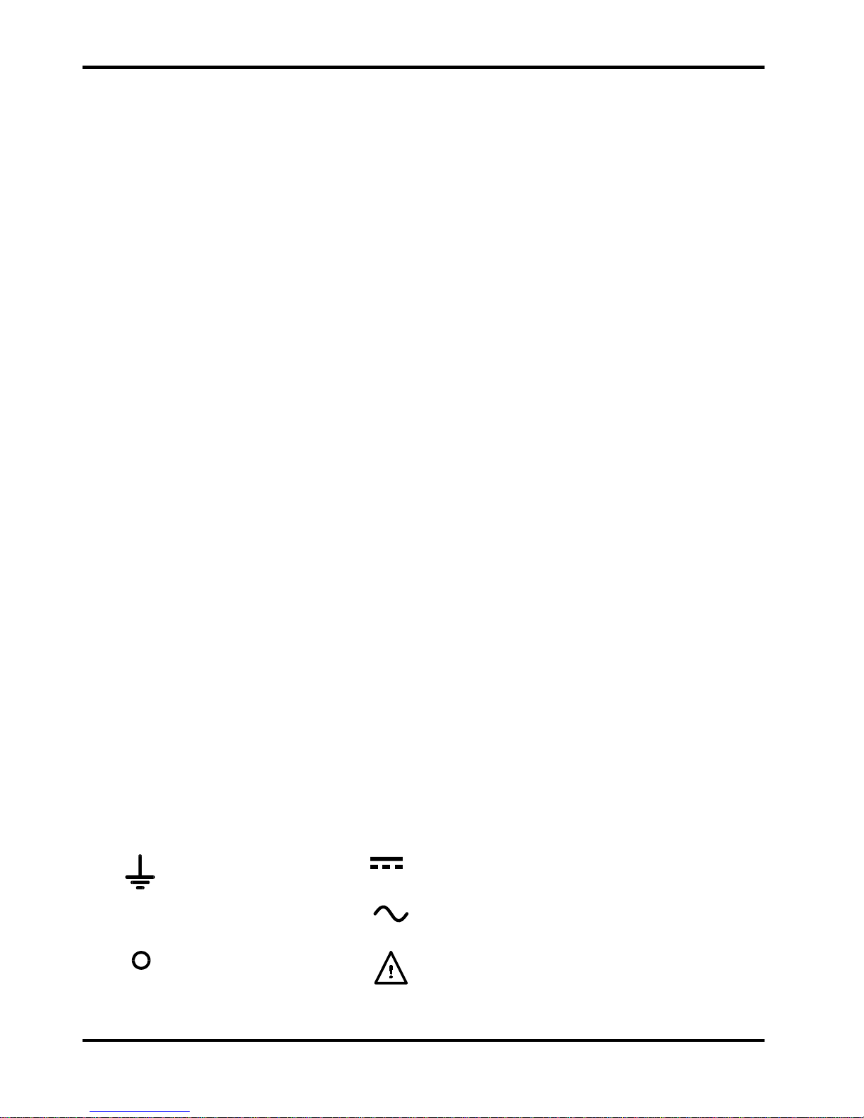
The following symbols are used on the instrument and in this manual:-
Earth (ground) terminal.
mains supply OFF.
l
mains supply ON.
alternating current (ac)
direct current (dc)
Caution – risk of danger.
Refer to the documentation (this
manual) to find out the nature of the potential hazard and any
actions which have to be taken.
Page 6
5
Installation
Mains Operating Voltage
This instrument has a universal input range and will operate from a nominal 115V or 230V mains
supply without adjustment. Check that the local supply meets the AC Input requirement given in
the Specification.
Mains Lead
Connect the instrument to the AC supply using the mains lead provided. Should a mains plug be
required for a different mains outlet socket, a suitably rated and approved mains lead set should be
used which is fitted with the required wall plug and an IEC60320 C13 connector for the instrument
end. To determine the minimum current rating of the lead-set for the intended AC supply, refer to the
power rating information on the equipment or in the Specification.
WARNING! THIS INSTRUMENT MUST BE EARTHED.
Any interruption of the mains earth conductor inside or outside the instrument will make the
instrument dangerous. Intentional interruption is prohibited.
Ventilation
The power supply is very efficient but nevertheless can generate significant heat at full power.
The supply relies on convection cooling only and it is therefore important that ventilation is never
restricted if performance and safety are to be maintained.
Connections
All connections are made from the f r ont panel.
The load should be connected to the positive (red) and negative (black ) terminals marked
OUTPUT. Connect to one or both outputs as appropriate f or t he s elect ed Mode, see Oper ation
section.
Warning! Voltages above 70Vdc are hazardous live according to EN 61010-1 and great care must
be taken when using the power supply at voltages above this level.
The universal safety binding posts used for the output meet the requirements f or r einforced
insulation for voltages up to 250Vdc because creepage and clearance to the t er m inal contacts is
>2.5mm even with the binding post fully open. However, it is highly recommended that the binding
posts are usually fully tightened and that connections are only made using leads fi t t ed with
fixed-shroud 4mm safety plugs. Make sure that the ci r cui t to which connections are made
is appropriately insulated; no accessible parts of the external circuit should become
hazardous live in normal or single fault condition as defined by EN61010-1.
Always make connections to the instrument with the OUTPUT off.
The terminal marked
is connected to the chassis and safety eart h ground.
Page 7
6
Operation
The operation of both outputs is identical in Mode A (independent mode) ; the following
description applies to both. In Mode B and Mode C only Output 2 is active and Output 1 is
disabled; the description therefore only applies to Output 2, see Mode Selection section.
Setting Up the Output
With the POWER switch on (l) and the output off the output voltage and current limit can be
accurately preset using the VOLTAGE and CURRENT controls; the left-hand meter shows the set
voltage and the right-hand meter s hows the set maximum current.
When the
output switch is switched on, the ON lamp lights; the left-hand m et er now shows
the actual voltage and the right-hand meter t he ac t ual load cur r ent .
Constant Voltage
The output voltage is adjusted using the coarse and fine VOLTAGE controls; the CURRENT
control sets the maximum current that can be supplied.
Constant Current
If the load resistance is low enough such that, at t he out put voltage set , a current greater than
the current limit setting would flow, the power supply will automatically move into constant current
operation. The current output is adjusted by the CURRENT control and the VOLTAGE controls
set the maximum voltage that can be generated.
The CC lamp lights to show constant current mode.
Instantaneous Current Output
The current limit control can be set t o limit the continuous output current to levels down to 10mA.
However, in com m on with all precision bench power supplies, a capacitor is connected acr os s
the output to maintain stability and good transient response. This capacitor charg es t o t he output
voltage and short-circuiting of the out put will produce a current pulse as t he capacitor dischar ges
which is independent of the current limit setting.
Mode Selection
The three operating modes are select ed by the front panel rotary switch situated between the
terminals.
Caution. Turn both outputs off before changing mode. Possible damag e t o t he c irc uit being
powered, and to the unit itself, may occur if the m ode is switched with either outp u t still on.
Mode A: With the switch in this position the outputs operate independently and are isolated f r om
one another. The voltage range on each output is 0-75V and the current range 0-2A.
Mode B: With the switch in this position only Output 2 is active; the voltage range is 0-75V and
the current range is 0-4A. The controls of Output 1 are inoperative and the display is blanked.
The terminals of Output 1 are isolated from those of Output 2.
Note that with the output switch of Output 1 in the ‘O N’ position the Output lamp st ill lights but t he
terminals remain open-circuit.
Note also that the range and scaling of t he c ur r ent limit control doubles when changing from Mode
A to Mode B, i. e. with the cont rol set for a 1.5A limit in Mode A, the limit becom es 3A in Mode B.
To avoid possible damage to the circuit being tested the outputs should be switched off before the
mode is changed and the current limit set to the desired value before the output is switched on.
Page 8
7
Mode C: With the switch in this posit ion only Output 2 is act ive; t he voltage range is 0-150V
and the current range is 0-2A. The controls of Output 1 are inoperative and the display is
blanked. The red terminal of Output 1 is isolated but the black terminal remains connected
internally to the black terminal of Out put 2.
Note that when the output switch of Output 1 is in the ‘ON’ position the Output lamp st ill lights
but the red terminal remains open-circuit.
Note also that the range and scaling of t he voltage cont r ols of Output 2 double when changing
from Mode B to Mode C, i.e. with the controls set for 60V in Mode B the output voltage
becomes 120V in Mode C. Care should therefore be taken to ensure that the outputs are
switched off before the mode is changed and that t he output is set to the correct voltage
before it is switched on.
Protection
The output has intrinsic short-circuit pr otection and is protected from r everse voltages by a diode;
the continuous reverse current must not exceed 3 Amps, although transients can be much higher.
The output is protected against exter nally applied forward voltages of up to 85V (Modes A and B)
or 170V (Mode C).
Connection to the Load
The load should be connected to the positive (red) and negative (black ) OUTPUT terminals. Both
are fully floating and either can be connected t o ground.
Warning! Voltages above 70Vdc are hazardous live according to EN 61010-1 and great care must
be taken when using the power supply at voltages above this level.
It is highly recommended that connections are only made using leads fi t t ed with fixedshroud 4mm safety plugs. Make sure that the circuit t o which connections are made is
appropriately insulated; no accessible parts of the external circuit should become
hazardous live in normal or single fault condition as defined by EN61010-1.
Always make connections to the instrument with the OUTPUT off.
Series or Parallel Conne ction with Other Outputs
The outputs of the power supply are fully floating and m ay be used in series with other power
supply units to generate high DC voltages up to 300V DC.
Warning! Voltages above 70Vdc are hazardous live according to EN 61010-1 and great care must
be taken when using the power supply at voltages above this level
The maximum permissible voltage between any terminal and earth ground (
) is 300VDC; the
maximum permissible voltage between either terminal of one output and any terminal of another
output on the same supply is also 300VDC.
All connections to the terminals must be made with the output sw i tched off on all units.
It should be noted that the unit can only source current and cannot sink it, thus units cannot be
series connected in anti-phase.
The unit can be connected in parallel with others to produce higher currents. Where several units
are connected in parallel, the output voltage will be equal to that of the unit with the highest
output voltage setting until the current dr awn exceeds its current limit set ting, upon which the
output will fall to that of the next highest setting, and so on. In constant current mode, units can
be connected in parallel to provide a current equal to the sum of the current limit settings.
Page 9

8
Maintenance
The Manufacturers or their agents overseas will provide repair for any unit developing a fault.
Where owner wish to undertake their own maintenance work , this should only be done by skilled
personnel in conjunction with the service manual which may be purchased directly from the
Manufacturers or their agents overseas.
Fuse
The correct fuse type is:
10 Amp 250V HBC time-lag(T), 5 x 20mm.
Note that the main func t ion of the fuse is to make t he inst rument safe and limit damage in the
event of failure of one of t he s witching devices. I f a fuse fails it is therefore very likely that the
replacement will also blow, because t he supply has developed a fault; in such circumstances the
instrument will need to be returned to the manuf act urer for service.
Make sure that only fuses of the req uir ed r ated current and specified type are used for
replacement. The use of makeshift fuses and the short-circuiting of fuse-holders is prohibited.
To replace a fuse, first disconnect the instrument from the AC supply. Remove the 6 cover
securing screws and lift off the cover. Replace the fuse with one of the correct type and refit the
cover.
Cleaning
If the PSU requires cleaning use a clot h t hat is only lightly dampened with water or a mild
detergent. Polish the display window with a soft dry cloth.
WARNING ! TO AVOID ELECTRIC SHOCK, OR DAMAGE TO THE PSU, NEVE R ALLOW
WATER TO G ET INSIDE THE CASE. TO AVO ID DAMAGE TO THE CASE OR DISPLAY
WINDOW NEVER CLEAN WITH SOLVENTS.
Page 10
9
Sécurité
Cet instrument est de Classe de sécurité 1 suivant la classificat ion I EC et il a été c onstruit pour
satisfaire aux impératifs EN61010-1 (I m pératifs de sécurité pour le matériel électrique en vue de
mesure, commande et utilisation en laboratoire). Il s'agit d'un instrument d' installation Catégorie
II devant être exploité depuis une alimentation monophasée habituelle.
Cet instrument a été soumis à des essais conf or m ém ent à EN61010-1 et il a été fourni en tout
état de sécurité. Ce manuel d'instructions contient des informations et avertissements qui doivent
être suivis par l'utilisateur afin d'assurer un f onc t ionnem ent de t oute sécurité et de conserver
l'instrument dans un état de bonne sécurité.
Cet instrument a été conçu pour êt r e utilisé en interne dans un environnement de pollution
Degré 2, plage de températures 5°C à 40°C, 20% - 80% HR (sans condensation). Il peut êt r e
soumis de temps à autre à des températures com pr ises ent r e + 5° C et –10° C sans dégradation
de sa sécurité. Ne pas l'utiliser lorsqu'il y a de la condensation.
Toute utilisation de cet instrum ent de m anièr e non spéc ifiée par ces instructions risque d'affecter
la protection de sécurité conférée. Ne pas utiliser l'inst r um ent à l' extér ieur des t ens ions
d'alimentation nominales ou de la gamme des conditions ambiantes spécif iées.
AVERTISSEMENT! CET INSTRUMENT DOIT ETRE RELIE A LA TERRE
Toute interruption du conduct eur de t erre secteur à l'intérieur ou à l'extérieur de l'inst r um ent
rendra l'instrument dangereux. Il est abs olument interdit d'effectuer une inter r upt ion à dessein.
Ne pas utiliser de cordon de prolongation sans conducteur de protection, car ceci annulerait sa
capacité de protection.
Lorsque l'instrument est relié à son alimentation, il est pos sible q ue les bor nes s oient sous
tension et par suite, l'ouverture des couvercles ou la dépose de pièces (à l'exception de celles
auxquelles on peut accéder manuellement) risque de mettre à découvert des pièces sous
tension. Il faut débrancher tout e s our ce de tension éventuelle de l'appareil avant de l'ouvrir pour
effectuer des réglages, remplacements, travaux d'entretien ou de réparations. Les
condensateurs qui se trouvent dans le bloc d'alimentation risquent de r es t er c har gés, même si le
bloc d'alimentation a été déconnecté de toutes les sources de tens ion, m ais ils se déchar geront
en toute sécurité environ 10 minutes après extinction de l'alimentation.
Eviter dans la mesure du possible d'effectuer des réglages, travaux de réparations ou d'entretien
lorsque l'instrument ouvert est branc hé à une sour c e d' alimentat ion, m ais si c' es t absolum ent
nécessaire, seul un technicien compétent au courant des r isques encourus doit effectuer ce
genre de travaux.
S'il est évident que l'instrument est déf ec t ueux, qu'il a été soumis à des dégâts mécaniques, à
une humidité excessive ou à une corrosion chimique, la protection de sécurité sera am oindr ie et
il faut retirer l'appareil, afin q u' il ne soit pas utilisé, et le renvoyer en vue de vérifications et de
réparations.
Uniquement remplacer les fusibles par des fus ibles d'int ensit é nom inale requise et de type
spécifié. Il est interdit d'utiliser des fusibles bricolés et de court-circuiter des porte-fusibles.
Eviter de mouiller l'instrument lors de son nettoyage.
Les symboles suivants se trouvent sur l'instrument, ainsi que dans ce manuel.
Borne de terre (masse)
courant continu (c.c.)
alimentation secteur OFF (éteinte)
courant alternatif (c.a. )
l
alimentation secteur ON (allumée)
Attention : risque de danger. Veuillez
consulter la documentation (ce manuel) pour
trouver la nature du danger potentiel et toute
action qui doit être prise.
Page 11

10
Installation
Tension de secteur opérationnelle
Cet instrument a une plage d'entrée universelle et il f onct ionne sur une alimentat ion sect eur de
115 V ou de 230 V, tension nominale, sans ajustement aucun. Vérifier que l'alimentation locale
satisfait aux impératifs d'ent r ée c.a. indiqués aux Caractéristiques techniques.
Câble secteur
Brancher l’appareil sur l’alimentation secteur à l’aide du cordon secteur four ni. S’il s’avère
nécessaire d’utiliser une fiche secteur destinée à un autre type de prise murale, employer un
cordon secteur correctement dimens ionné et hom olog ué en l’éq uipant de la fiche murale voulue
et d’un connecteur IEC60320 C13 du côté de l’appareil. Pour déterminer l’intensité nominale
minimale du cordon en fonction de l’alimentation sur secteur prévue, consult er les
caractéristiques de puissance nominale fig ur ant s ur le m at ér iel ou dans le chapitr e
Spécifications.
AVERTISSEMENT ! CET APPAREIL DOI T ETRE RELIÉ À LA TERRE.
Toute interruption du conduct eur de t erre de la prise secteur à l'intérieur ou à l'extérieur de
l’appareil rendra ce dernier dangereux. Il est interdit d'eff ec t uer une c oupur e int ent ionnell e.
Ventilation
L’alimentation est très performante, mais elle peut toutefois génér er beauc oup de chaleur à
puissance maximale. L’alimentation a besoin d’un refroidissement par convection uniquement et
il est donc important que la ventilation ne soit jamais réduite, afin d’assurer une bonne
performance et sécurité.
Connexions
Toutes les connexions sont effectuées au panneau avant.
La charge doit être reliée aux bornes positive (rouge) et négative (noire) marquées OUTPUT
(Sortie). Relier à une sortie ou aux deux, selon les besoins, pour le mode sélectionné, voir la
section Fonctionnement.
Avertissement ! Les tensions supérieures à 70 Vcc sont dangereus es sous t ens ion selon la norm e
EN 61010-1 et le plus grand soin doit être pris lors de l'ut ilisation de tensions supérieures à ce
niveau.
Les bornes d'attache de sécurité universelles utilisées pour la sortie satisfont aux conditions
d'isolation renforcée pour des tensions supérieur es à 250 Vcc, car les lignes de fuite et la distance
d'isolement jusqu'aux contacts de la borne sont >2,5 mm, même lorsque la borne est t otalement
ouverte. Toutefois, il est vivement recommandé de serrer les bornes d'attache à fond et de
n’effectuer les connexions qu'à l'aide de f ils munis de bouchons de sécurité à protection
fixe de 4 mm. S’assurer que le circuit sur lequel sont effectuées les connexions est
correctement isolé ; aucune des pièces accessibl es du ci r cui t externe ne devrait être
dangereuse lorsque l'appareil est sous tension dans des conditions normal es ou l orsqu'une
seule faute est détectée, conformément à l a nor m e EN61010-1.
OUTPUT (sortie) doit toujours être hors tension lors de la connexion à l’instrument.
La borne désignée
est reliée au châssis et à la terre de protection.
Page 12
11
Fonctionnement
Le fonctionnement des deux sorties est identique en mode A (mode indépendant); la description
suivante s'applique aux deux. En mode B et en mode C seule la sortie 2 est active et la sortie 1
est désactivée; la description s'applique donc uniquement à la sor t ie 2, voir la section Sélection
de mode.
Réglage de la sortie
L’interrupteur POWER (alimentation) sur (l) et la sor tie éteinte, il est possible de régler avec
précision la limite de tension et de courant de sortie au moyen des commandes VOLTAGE
(Tension) et CURRENT (Courant); l’appareil de mesure gauche indique la tension réglée et
l’appareil droit le courant maximum réglé.
Lorsque le commutateur de sortie
est sur marche, le témoin ON (Marche) s’allume;
l’appareil de mesure gauche indique alors la tension véritable et l’appareil droit le courant de
charge véritable.
Tension constante
Les commandes VOLTAGE de réglage grossier et de pr écision per m et tent d’ajuster la tension de
sortie; la commande CURRENT règle le courant maximum qui peut être fourni.
Courant constant
Si la résistance de charge est suffisamment basse qu’un courant supérieur au réglage de limite
de courant puisse passer pour la tension de sortie réglée, l’alimentation passera
automatiquement en mode de fonc t ionnem ent de c our ant c onstant . La commande CURRENT
ajuste le courant de sortie et les commandes VO LTAGE règ lent la tens ion maximale q ui peut êt r e
engendrée. Le témoin CC s’allume pour indiquer le mode de courant cons tant.
Sortie de courant instantanée
Il est possible de régler la commande de limite de courant pour limit er le cour ant de s or t ie
continu à des niveaux aussi bas que 10 mA. Toutefois, ainsi que c’est le cas de toutes les
alimentations de précision sur banc, un condensateur est relié aux bornes de la sortie, afin de
maintenir la stabilité, ainsi qu’une bonne réponse transitoire. Ce condensateur s e char ge jusqu’à
la tension de sortie, et le court-circuitage de la sortie produira une impulsion de courant, lors du
déchargement du condensateur indépendamment du r églage de limite de courant.
Sélection de mode
Les trois modes de fonctionnement sont sélectionnés par le commutateur rotatif du panneau
avant situé entre les bornes.
Attention. Désactiver les deux sorties avant de changer de mode. O n r isque en effet d'endommager
le circuit alimenté, ainsi que l'appareil en question si le mode est opérationnel lorsqu'une des deux
sorties est toujours activée.
Mode A: Le commutateur dans cet t e pos it ion, les s or t ies fonctionnent indépendamment et elles
sont isolées l'une de l'autre. La plage de tension à chaq ue sortie est de 0-75 V et la plage
d'intensité 0-2 A.
Mode B: Le commutateur dans cette position, seule la sortie 2 est ac t ive; la plage de tension est
de 0-75 V et la plage d'intensité 0-4 A. Les commandes de la sortie 1 sont inopérationnelles et
l'affichage est occulté. Les bornes de la sortie 1 sont isolées de celles de la sortie 2.
Noter que lorsque la sortie 1 du commutateur de s or t ie est s ur " ON" (Marche), le témoin de sortie
est toujours allumé, mais la borne reste en cir cuit ouvert .
Noter également que la gamme et la m ise à l'éc helle de la comm ande de limit e de cour ant doublent
de valeur lorsqu'on passe du mode A au mode B, c.-à-d. que lorsque la commande est réglée à
une limite de 1,5 A en mode A, la limite passe à 3 A en mode B. Pour éviter d'endommager le circuit
soumis aux essais, il est recommandé de désactiver les sorties avant de changer de m ode et de
régler la limite de courant à la valeur désirée avant d'activer la sortie.
Page 13
12
Mode C: Le commutateur dans cette position, seule la sort ie 2 est active; la plage de tension est de
0-150 V et la plage d'intensité 0-2 A. Les commandes de la sortie 1 sont inopérationnelles et
l'affichage est occulté. La borne rouge de la sortie 1 est isolée, mais la borne noire reste
connectée en interne à la borne noire de la sortie 2.
Noter que lorsque la sortie 1 du commutateur de s or t ie est sur "ON" (Marche), le témoin de sortie
est toujours allumé, mais la borne rouge reste en circuit ouvert.
Noter également que la gamme et la m ise à l'échelle des commandes de tension de la sortie 2
doublent de valeur lorsqu'on passe du mode B au mode C, c.-à-d. q ue lor sque les commandes
sont réglées à 60 V en mode B, la tension de sortie passe à 120 V en mode C. Il faut donc veiller à
désactiver les sorties avant de changer de mode et à rég ler la sor t ie à la tens ion cor r ecte avant de
l'activer.
Protection
La sortie dispose d’une protection intrinsèque contre les courts-circuits et elle est protégée contr e
la tension inverse par une diode; le courant inverse continu ne doit pas dépasser 3 A, bien qu’il
soit possible que l’intensité des transitoires soit nett em ent supérieure.
La sortie est protégée contre des t ens ions direc t es appliq uées en exter ne j us qu'à 85 V (Modes A
et B) ou jusqu'à 170 V (Mode C).
Connexion à la charge
La charge devra être connectée aux bornes OUTPUT positive (rouge) et négative (noire). Les
deux sont entièrement flottantes et l’une ou l’autre peuvent êtr e connec t ées à la m ass e.
Avertissement ! Les tensions supérieures à 70 Vcc sont dangereuses sous t ension selon la norm e
EN 61010-1 et le plus grand soin doit être pris lors de l'ut ilisation de t ensions supérieures à ce niveau.
Il est vivement recommandé de n’effectuer de connexions qu' à l ' ai de de f ils munis de
bouchons de sécurité à protection fixe de 4 mm. S’assur er que l e circuit sur lequel sont
effectuées les connexions est correctement i solé ; aucune des pièces accessibles du circuit
externe ne devrait être dangereuse lorsque l'appareil est sous tension dans des condit ions
normales ou lorsqu'une seule faute est détect ée, conf or m ém ent à l a nor m e EN61010-1.
OUTPUT (sortie) doit toujours être hors tension lors de la connexion à l'instrument.
Connexion en série ou en parallèle avec d’autres sorties
Les sorties de l’alimentation sont entièrement f lot tant es et elles peuvent être utilisées en série
avec d’autres blocs d’alimentation, afin de produire des tensions c.c. j usqu’à 300 V c.c.
Avertissement ! Les tensions supérieures à 70 Vcc sont dangereus es sous t ens ion selon la norm e
EN 61010-1 et le plus grand soin doit être pris lors de l'ut ilisation de t ensions supérieures à ce niveau.
La tension maximale admissible entre une borne et la terre ( ) est de 300 V c.c.; la tension
maximale admissible entre la borne d'une sortie et la borne d'une aut r e s or t ie de la même
alimentation est également de 300 V c.c.
AVERTISSEMENT! Effectuer toutes les connexions aux bornes, l a sor t ie désactivée à tous
les appareils.
Il faut noter que le bloc peut uniquem ent recevoir du courant, mais non le consommer, de sorte
qu’il n’est pas possible de mettre en opposition de phase les blocs reliés en série.
Il est possible de relier le bloc en parallèle avec d’autres, afin de produire des courants de haute
intensité. Lorsque plusieurs blocs sont reliés en parallèle, la tension de sort ie doit être égale à
celle du bloc de réglage de tension de sortie le plus élevé, jusqu’à ce que le cour ant cons om m é
dépasse le réglage de limite de courant, auquel cas la sortie desc end à celle du réglage le plus
haut suivant, etc. En mode de courant constant, les blocs peuvent être reliés en parallèle, afin
de donner un courant égal à la somme des réglag es de limit e de c our ant .
Page 14

13
Maintenance
Le Constructeur ou ses agents à l'étrang er répareront tout bloc qui tombe en panne. Si le
propriétaire de l'appareil décide d'effectuer lui-même la maintenance, c eci doit uniquement être
effectué par un personnel spécialisé qui doit se référer au m anuel d’ent r et ien que l'on peut se
procurer directement auprès du Constr uct eur ou de ses agents à l'étranger.
Fusible
Type de fusible correct:
10 A 250 V HBC temporisé (T), 5 x 20 mm.
Il faut noter que l’objet pr incipal de ce fus ible est de r endr e l’instrument non dangereux et de
limiter les dégâts en cas de panne d’un des dispositifs de commutation. En cas de panne d’un
fusible, il est très probable que le f usible de rechange sautera également, étant donné q ue
l’alimentation est probablement défectueuse; lorsque c’est le cas, il faudra renvoyer l’instrument
chez le constructeur en vue de réparations.
Uniquement remplacer les fusibles par des fus ibles d'int ensit é nom inale requise et de type
spécifié. Il est interdit d'utiliser des fusibles bricolés et de court-circuiter des porte-fusibles.
Pour remplacer un fusible, commencer par débranc her l ’instrument de l’alimentation c.a. Enlever
les 6 vis d’immobilisation du couvercle, puis enlever le couvercle. Remplacer le fusible par un
autre de type correct, puis remett r e le couvercle.
Nettoyage
S'il faut nettoyer le bloc d'alimentation, utiliser un chiffon légèrement imbibé d'eau ou d'un
détergent doux. Nettoyer le cadran d'affichage au moyen d'un chiffon sec et doux.
AVERTISSEMENT! EMPECHER TOUTE INTRODUCTION D'EAU DANS LE BOITIER AFI N
D'EVITER TOUT CHOC ELECTRIQUE ET DEGATS AU BLOC D'ALIMENTATION. NE JAMAIS
UTILISER DE DISSOLVANTS POUR NETTOYER LE BLOC, AFI N D' EVITER
D'ENDOMMAGER LE BOITIER OU LE CADRAN D’AFFICHAGE.
Page 15

14
Sicherheit
Dieses Gerät wurde nach der Sicherheitsklasse (Schutzart) I der I EC-Klassifikation und gemäß
den europäischen Vorschriften EN61010-1 (Sicherheitsvorschriften für elektrische Meß-, Steuer,
Regel- und Laboranlagen) entwickelt. Es handelt sich um ein G er ät der Installationskategorie II,
das für den Betrieb von einer normalen einphasigen Versorgung vorgesehen ist.
Das Gerät wurde gemäß den Vorschriften EN61010-1 geprüft und wurde in sicherem Zustand
geliefert. Die vorliegende Anleitung enthält vom Benutzer zu beachtende Informationen und
Warnungen, die den sicheren Betrieb und den sicheren Zustand des Gerätes gewährleisten.
Dieses Gerät ist f ür den Bet r ieb in Innenr äumen der Umgebungsklass 2 , für einen
Temperaturbereich von 5° C bis 40° C und 20 - 80 % r elat ive Feuchtig keit (nicht kondensierend)
vorgesehen. Gelegentlich kann es Temperaturen zwischen +5° und –10°C ausgesetzt sein, ohne
daß seine Sicherheit dadurch beeinträchtigt wird. Betr eiben Sie das Ger ät jedoch auf keinen Fall,
solange Kondensation vorhanden ist.
Ein Einsatz dieses Geräts in einer Weise, die für diese Anlage nicht vorgesehen ist, kann die
vorgesehene Sicherheit beeinträchtigen. Auf keinen Fall das Gerät außerhalb der angeg ebenen
Nennversorgungsspannungen oder Umgebungsbeding ungen betreiben.
WARNUNG! - DIESES G ERÄT MUSS GEERDET WERDEN!
Jede Unterbrechung des Netzschutzleiters innerhalb oder außerhalb des Geräts macht das
Gerät gefährlich. Eine absichtliche Unter br echung ist verboten. Die Schutzwirkung darf durch
Verwendung eines Verlängerungskabels ohne Schut zleiter nicht aufgehoben werden.
Ist das Gerät an die elektrische Versorgung angeschlossen, so können die Klemmen unter
Spannung stehen, was bedeutet, daß beim Entfernen von Ver kleidungs- oder sonstigen Teilen
(mit Ausnahme der Teile, zu denen Zugang mit der Hand möglich ist) höchstwahrscheinlich
spannungsführende Teile bloßgelegt weden. Vor jeglichem Öffnen des Geräts zu Nachstell-,
Auswechsel-, Wartungs- oder Reparaturzwecken, G er ät stets von sämtlichen Spannungsquellen
abklemmen. Kondensatoren in der Stromversorgung können auch noch nac h Abschalten
sämtlicher Stromversorgung Spannung führen, sie entladen sich jedoch innerhalb von etwa 10
Minuten nach Spannungsabschaltung.
Jegliche Nachstellung, Wartung und Reparatur am geöffneten, unter Spannung stehenden
Gerät, ist nach Möglichkeit zu vermeiden. Falls unvermeidlich, sollten solche Arbeiten nur von
qualifiziertem Personal ausg eführt werden, das sich der Gefahr en bewußt ist.
Ist das Gerät eindeutig f ehler behaf t et, bzw. wurde es m ec hanisch besc hädig t, übermäßiger
Feuchtigkeit oder chemischer Korr osion ausgesetzt, so können die Schutzeinrichtungen
beeinträchtigt sein, weshalb das Gerät aus dem Verkehr zurückgezogen und zur Überprüfung
und Reparatur eingesandt werden sollte.
Sicherstellen, daß nur Sicherungen der vorgeschriebenen Stromstärke und des vorg esehenen
Typs als Er satz verwendet werden. Provisorische “Sicherungen” und der Kurzschluß von
Sicherungshaltern ist verboten.
Beim Reinigen darauf achten, daß das Gerät nicht naß wird.
Am Gerät werden folgende Symbole verwendet:
Erdungsklemme
Gleichstrom
l
Netz ON (ein)
Wechselstrom
Netz OFF (aus)
Achtung – Gefahr.
Lesen Sie bitte die Dokumentation
(dieses Handbuch), um die Art der möglichen Gefahr und
etwaige Gegenmaßnahmen herauszufinden.
Page 16

15
Installation
Netzbetriebsspannung
Das Gerät besitzt einen universellen Eingangsbereich und kann ohne jede weitere Einst ellung
mit einer Nenn-Netzversorgung von 115 oder 230 V betrieben werden. Stellen Sie sicher, daß die
Versorgung am Ort den in der Spezifikation aufgeführten Eingangsanforderungen entspricht.
Netzkabel
Schließen Sie das Gerät unter Verwendung des mitgelieferten Netzkabels an die
Wechselspannungsversorgung an. Falls ein Netzstecker für eine unterschiedliche
Netzsteckdose erforderlich ist, m uss ein g eeigneter und zugelassener Netzkabelsatz verwendet
werden, der mit dem geeigneten Wandstecker und einem IEC60320 C13-Stecker für das
Geräteende versehen ist. Zur Bestimmung der Mindest-Nennstromstärke des Kabelsatzes für
die beabsichtigte Wechselspannungsversorg ung sind die Informationen zu Leistungswerten auf
dem Gerät bzw. in seiner Spezifikation hinzuzuziehen.
ACHTUNG! DIESES GERÄT M USS G EERDET SEIN
Jegliche Unterbrechung der Netzerde, ob im Inner n oder außerhalb des Geräts, macht das Gerät
zur Gefahrenquelle! Eine absichtliche Unterbrechung ist verboten!
Ventilation
Obwohl die Stromversorgung äußerst effizient arbeitet kann sie bei voller Leistung ein
beträchtliches Maß an Wärme er zeug en. Die Kühlung der Stromversorgung er folgt
ausschließlich durch Konvektion, weshalb es wichtig ist, daß die Ventilation niemals
eingeschränkt wird, wenn Leistung und Sicherheit auf r ec ht er halt en werden sollen.
Anschlüsse
Sämtliche Anschlüsse erfolgen von der Fronttafel aus.
Der Verbraucher it an die positive (rote) und negative (schwarze) Klemme mit der Bezeichnung
OUTPUT (Ausgang) anzuschließen. Nehmen Sie den Anschluß an an einen oder beide
Ausgänge vor, dem gewählten Modus entsprechend. Siehe hierzu Betriebsabschnitt.
Achtung! Spannungen über 70 VDC sind nach EN 61010-1 lebensgefährlich. Daher ist bei
Netzteilspannungen über diesem Wert äußerst vorsicht ig vorzugehen.
Die Universal-Sicherheitsanschlussklemmen am Ausgang entsprechen den Anforderungen für
verstärkte Isolierung bei Spannungen bis 250 VDC, da Kriechweg und Abstand zu den
Anschlusskontakten auch bei vollständig geöffneten Anschlussklemmen >2,5 mm betragen.
Es wird jedoch sehr empfohlen, die Anschlussklemmen immer ganz anzuziehen und Anschlüsse
nur mit Kabeln auszuführen, die mit 4 m m Si cher hei tssteckern und fester Umm ant el ung
ausgestattet sind. Achten Sie darauf, dass die angeschlossene Schaltung ausreichend
isoliert ist. Zugängli che Teile der externen Schaltung dürfen unter normalen oder
Störbedingungen keine lebensgefährliche Spannungen führen (siehe EN61010-1).
Anschlüsse am Gerät nur bei abgeschaltetem OUTPUT ausführen.
Die mit dem Symbol
gekennzeichnete Klemme ist mit dem Chassis und der Schut zerde
verbunden.
Page 17

16
Betrieb
Bei Modus A (unabhängiger Modus) ist der Betrieb beider Ausgänge identisch; Die
anschließende Beschreibung gilt für beide. Bei Modus B und C ist nur Ausgang 2 aktiv, während
Ausgang 1 deaktiviert ist . Die Beschreibung gilt also nur für Ausgang 2. Siehe Abschnitt über
Moduswahl.
Einstellung des Ausgangs
Bei eingeschaltetem POWER-Schalter (Netz I) und ausgeschaltetem Ausgang
läßt sich die
Ausgangsspannung und Strombegrenzung mit Hilfe der Knöpfe VOLTAGE (Spannung) und
CURRENT (St r om ) genau voreinstellen. Die linke Anzeige zeigt die eingestellte Spannung und
die rechte den eingestellten Maximalstrom an.
Wenn der Ausgangsschalter
eingeschaltet wird, leuchtet die ON (Ein)-Leuchte auf. Jetzt
wird auf der linken Anzeige die Istspannung und an der rechten Anzeige der I st-Laststrom
angezeigt.
Konstantspannung
Die Ausgangsspannung wird mittels der Grob- (coarse) und Feindrehknöpfe (fine) von VOLTAGE
reguliert. Mit dem Knopf CURRENT (Strom) wird der Maximalstrom eingestellt, der zur Verfügung
gestellt werden kann.
Konstantstrom
Ist der Belastungswiderstand ausreichend niedrig, daß bei der eingestellten Ausgangsspannung
ein Strom fließen würde, der größer wäre als die eingestellte Strombegrenzung, so schaltet die
Stromversorgung automatisch auf konstanten Strombetrieb. Der Stromausgang wird mit dem
Knopf CURRENT eingestellt und die maximal generierbare Spannung mit dem Knopf VOLTAGE.
Die CC-Leuchte leuchtet bei eingeschaltetem Konstantstr om modus auf.
Augenblickstromausgang
Mit der Strombegrenzung kann der kontinuierliche Ausgangsstrom bis auf 10 mA begrenzt
werden. Wie bei allen Präzisions-Stromversorgungs-Tischgeräten ist der Ausgang zur
Aufrechterhaltung der Stabilität und zwecks gutem Einschwingverhalten mit einem Kondensator
versehen. Der Kondensator wird bis zur Höhe der Ausgangsspannung aufgeladen. Ein
Kurzschließen des Ausgangs bewirkt beim Entladen des Kondensators einen Stromimpuls, der
von der Strombegrenzungseinstellung unabhängig erfolgt.
Moduswahl
Die drei Betriebsmodi werden mit Hilfe des zwischen den Klemmen befindlichen Drehschalters
an der Fronttafel gewählt.
Vorsicht! Vor dem Umschalten auf einen anderen Modus beide Ausgänge abschalten. Wird
umgeschaltet, solange einer der Ausgänge noch eingeschaltet ist, kann Schaden an dem
versorgten Stromkreis und am Gerät selbst anger icht et werden.
Modus A: Befindet sich der Schalter in dieser Stellung, sind die Ausgänge voneinander getrennt
und arbeiten unabhängig voneinander. Der Spannungsber eich eines j eden Ausgangs beträgt
0 – 75 V und der Strombereich 0 – 2 A.
Modus B: Befindet sich der Schalter in dieser Stellung, ist nur Ausgang 2 aktiv. Der
Spannungsbereich beträgt dann 0 – 75 V und der Strombereich 0 – 4 A. Die
Bedienungselemente für Ausgang 1 sind dann außer Betrieb gesetzt und die Anzeige ist
ausgeblendet. Die Klemmen von Ausgang 1 sind von denen des Ausgang s 2 getrennt.
Beachten Sie bitte, daß solange sich der Ausgangsschalter von Ausgang 1 in EIN-Stellung
befindet, die Ausgangsleuchte aufleuchtet, die Klemmen jedoch nach wie vor einen offenen
Stromkreis bilden.
Page 18

17
Beachten Sie bitte auch, daß sich Umfang und die Skalierung der Strombegrenzung beim
Umschalten von Modus A auf Modus B verdoppeln; d.h. erfolgt die Einstellung auf eine 1,5 ABegrenzung in Modus A, so beträgt die Begrenzung in Modus B 3 A. Um die Möglichkeit eines
Schadens am zu prüfenden Stromkreis zu vermeiden, sind vor dem Umschalten die Ausgänge
auszuschalten und die Strombegrenzung ist auf den gewünschten Wert einzustellen, bevor der
Ausgang wieder eingeschaltet wird.
Modus C: Befindet sich der Schalter in dieser Stellung, so ist nur Ausgang 2 aktiv. Der
Spannungsbereich beträgt 0 – 150 V und der Strombereich 0 – 2 A. Die Bedienungs elemente des
Ausgangs 1 befinden sich außer Betrieb und die Anzeige ist ausgeblendet. Die rote Klemme von
Ausgang 1 ist getrennt, doch bleibt die schwarze Klemme intern mit der schwarzen Klemme von
Ausgang 2 verbunden.
Beachten Sie bitte, daß wenn sich der Ausgangsschalter von Ausgang 1 in der EIN-Stellung
befindet, die Ausgangsleuchte nach wie vor aufleuchtet, die rote Klemme jedoch nach wie vor
einen offenen Stromkreis bildet.
Beachten Sie bitte auch, daß sich Umfang und die Skalierung der SpannungsBedienungselemente von Ausgang 2 beim Umschalten von Modus B auf Modus C verdoppeln;
d.h., daß wenn bei Modus B eine Einstellung von 60 V erfolgt, im Modus C die
Ausgangsspannung 120 V beträgt. Aus diesem Grund ist darauf zu achten, daß vor dem
Umschalten des Modus die Ausgänge ausgeschaltet werden und daß der Ausgang vor dem
Einschalten auf die richtige Spannung eingestellt wird.
Schutzvorrichtungen
Der Ausgang ist mit einem eigenen Kurzschlußschutz versehen und mittels Diode vor
Umkehrspannungen geschützt. Kontinuierlicher Um kehrstrom darf 3 Amp nicht überschreiten.
Transiente Ströme können jedoch wesentlich höher liegen.
Der Ausgang ist vor extern angelegten Durchlaßspannungen von bis zu 85 V (Modi A und B) oder
170 V (Modus C) geschützt.
Anschluß an den Verbr aucher
Die Last sollte an die mit OUTPUT gekennzeichneten positiven (rot) und negat iven (schwarz)
Klemmen angelegt werden. Beide Klemmen sind galvanisch getr ennt und können daher an Erde
gelegt werden.
Achtung! Spannungen über 70 VDC sind nach EN 61010-1 lebensgefährlich. Daher ist bei
Netzteilspannungen über diesem Wert äußerst vorsicht ig vorzugehen.
Es wird sehr empfohlen den Anschluss nur mit Kabeln auszuführen, die mit 4 mm
Sicherheitssteckern und fester Ummantelung ausgestattet sind. Achten Sie darauf, dass die
angeschlossene Schaltung ausreichend isoliert i st . Zugängliche Tei l e der ext er nen
Schaltung dürfen unter normalen oder Störbedingungen keine lebensgefähr l iche
Spannungen führen (siehe EN61010-1).
Anschlüsse am Gerät nur bei ausgeschalteten Ausgang (OUTPUT) kontaktieren.
Reihen- und Parallelschaltung mit anderen Ausgängen
Da der Ausgang des Netzteils vollständig potentialfrei ist, kann er mit anderen Netzgerät en zur
Erzeugung hoher Gleichspannungen bis maximal 300V in Reihe geschaltet werden.
Achtung! Spannungen über 70 VDC sind nach EN 61010-1 lebensgefährlich. Daher ist bei
Netzteilspannungen über diesem Wert äußerst vorsicht ig vorzugehen.
Die maximal zulässige Spannung zwischen einer beliebigen Klemme und Erde ( ) beträgt
300 V Gleichspannung. Die maximal zulässige Spannung zwischen einer der beiden Klemm en eines
Ausgangs und einer beliebigen Klemme eines anderen Ausgangs desselben Geräts beträgt
ebenfalls 300 V Gleichspannung. Sämtliche Anschlüsse an die Klemmen müssen bei
ausgeschaltetem Ausgang aller Einheiten erfolgen.
Page 19

18
Zu beachten ist dabei, daß das Gerät ausschließlich stromlief ernd, nicht aber stromziehend
arbeiten kann, und daß die Geräte daher nicht gegenphasig in Reihe geschaltet werden können.
Das Gerät kann zur Erzeugung einer höheren Stromabgabe mit anderen G er ät en parallel zu
diesen geschaltet werden. Wenn mehrer e G eräte parallel geschaltet werden, entspricht die
Ausgangsspannung der Ausgangsspannung des Geräts, bei dem der Einstellwert für die
Ausgangsspannung am höchsten ist, bis die Stromaufnahme den bei diesem Ger ät eingestellten
Grenzwert überschreitet, woraufhin der Ausgang auf die zweilhöchste Einstellung abfällt, und so
weiter. Im Konstantstrombetrieb können Geräte parallel geschaltet werden, wodurch sich eine
Stromabgabe erreichen läßt, die der Summe der Einstellwerte f ür die Strombegrenzung
entspricht.
Wartung
Die Hersteller bzw. der en Vertretungen im Ausland bieten die Reparatur von Geräten an, bei
denen eine Störung aufgetreten ist. Wenn der Eig ent ümer die Wartungsarbeiten selbst
durchführen möchte, hat er dafür Sorge zu tragen, daß diese Arbeiten ausschließlich von
entsprechend qualifiziertem Personal und gemäß W ar tungshandbuch ausgeführt werden, das
direkt von den Herstellern oder deren Vertretungen im Ausland bezogen werden kann.
Sicherungen
Korrekter Sicherungstyp:
Träge Hochleistungssicherung (T) 10 Amp, 250 V, 5 x 20 mm
Beachten Sie bitte, daß die Hauptfunktion der Sicherung der Schutz von Personen sowie
Geräteteilen ist bzw. die Begrenzung solcher Schäden im Falle von Störungen an den
Schaltgeräten. Brennt eine Sicherung durc h, so ist es höchst wahrscheinlich, daß auch ihr Ersatz
durchbrennt, weil eine Störung im Gerät vorliegt. In einem solchen Falle ist es erforderlich, daß
das Gerät vom Hersteller repariert wird.
Achten Sie darauf, daß nur Sicherungen der vorg eschriebenen Stromstärke und des
angegebenen Typs als Er satzsicherungen verwendet werden. Die Verwendung von
Behelfssicherungen und das Kurzschließen von Sicherungshaltern ist verboten.
Zum Auswechseln einer Sicherung zuerst das Gerät von seiner Wechs elst r om versor gung
trennen. Dann die 6 Befestigungsschr auben des G ehäus es entfernen und danach das Gehäuse
abheben. Sicherung durch eine korrekte Ersatzsicherung ersetzen und Gehäuse wieder
montieren.
Reinigung
Falls die Stromversorgung der Reinigung bedarf, einen mit Was ser oder einem m ilden Deter gens
angefeuchteten Lappen benutzen. Anzeigefenster mit einem weichen, trockenen Lappen
polieren.
WARNUNG! ZUR VERMEI DUNG EINES ELEKTRISCHEN SCHLAGS BZW. BESCHÄDIGUNG
DER STROMVERSORGUNGSEINHEI T, DAFÜR SO RGEN, DASS KEIN WASSER INS
GEHÄUSE EINDRINGT. UM SCHADEN AM GEHÄUSE BZW. AM ANZEIGEFENSTER ZU
VERMEIDEN, KEINE LÖSUNG S M ITTEL ZUR REINIGUNG VERWENDEN!
Page 20

19
Sicurezza
Questo strumento appartiene alla Categoria di Sicurezza 1, secondo la classif ica I EC, ed è stat o
progettato in modo da soddisfare i criter i EN61010-1 (requisiti di Sicurezza per Apparecchiature
di misura, controllo e per uso in laboratorio). È uno str um ento di Categoria d’installazione II ed è
inteso per il funzionamento con un’alimentazione normale monofase.
Questo strumento ha superato le prove previste da EN61010-1 e viene f or nit o in uno stato di
sicurezza normale. Questo manuale contiene informazioni e avvertenze che devono essere
seguite per assicurare un funzionamento s icur o e m ant ener e lo strumento in condizioni di
sicurezza.
Questo strumento è proget tat o per uso all’inter no e in un ambient e d’inq uinam ent o G rado 2,
entro la gamma di temperatura da 5° C a 40C°, con um idit à r elat iva (non condensant e) di
20% - 80%. Può occasionalmente essere assog gettato a temperature f r a + 5° C e –10° C senza
comprometterne la sicurezza. Non usare in presenza di condensazione.
L’uso dello strumento in maniera non conforme a quanto specificato in queste ist ruzioni potrebbe
pregiudicare la protezione di cui è dotato. Non usare lo strumento per m isur ar e t ens ioni al di
sopra dei valori nominali o in condizioni ambientali al di fuori di quelle specificate.
ATTENZIONE: QUESTO STRUMENTO DEVE ESSERE COLLEGATO A TERRA
Una qualsiasi interruzione sia interna che esterna del collegamento a t er r a r ende per icoloso
questo strumento. È proibito interrompere questo collegamento deliberatam ent e. L’azione
protettiva non deve essere negata dall’uso di una prolunga priva conduttore di protezione.
Quando lo strumento è collegato all’alimentazione, alcuni morsetti sono sott o t ens ione e
l’apertura dei coperchi o la rimozione di parti (eccetto quei componenti accessibili senza l’uso di
attrezzi) può lasciare scoperti i morsetti sotto t ens ione. Pr im a di aprirla per eseguire regolazioni,
manutenzione o riparazioni, l’apparecchiatura deve essere staccata da tutte le sorgenti di
tensione. I condensatori collegati all’alimentazione interna possono essere carichi anche dopo
aver staccato l’alimentazione ma si scaricano in circa 10 minuti dopo aver staccato la corrente.
Per quanto possibile, si consiglia di evitare qualsiasi operazione di regolazione e riparazione
quando lo strumento è sotto tensione e, qualora fosse inevitabile, dette operazioni devono
essere eseguite da una persona specializzata in materia, che sia pienamente conscia del
pericolo presente.
Quando sia chiaro che lo strumento è difett oso, o che ha subito un danno meccanico, un
eccesso di umidità, o corrosione a mezzo di agenti chimici, la sicurezza potrebbe essere stata
compromessa e lo strumento deve essere ritirato dall’uso e rimandato indietro per le prove e le
riparazioni del caso.
Assicurarsi di usare solo fusibili della portata giusta e del tipo corretto durante eventuali
sostituzioni. Sono proibiti sia l’uso di fusibili improvvisati che il corto circuito deliberato dei
portafusibili.
Evitare di bagnare lo strumento quando lo si pulisce.
Sullo strumento e in questo manuale si fa uso dei seg uenti simboli.
Terminale di terra
Corrente Continua
l
alimentazione ON (accesa)
Corrente Alternata
alimentazione OFF (spenta)
Attenzione – pericolo.
Consultare il presente
manuale per individuare la tipologia del rischio
potenziale e gli interventi da effettuare.
Page 21
20
Installazione
Tensione d’esercizio
Questo strumento è dotato di un’entr at a universale e funziona con un’alimentazione a 115V o
230V senza regolazione. Controllare che la rete locale soddisfi i requisiti d’entrata indicat i nella
specifica.
Cavo d’Alimentazione
Collegare lo strumento all’alimentazione di rete in corrente alternata utilizzando il cavo fornito. Se
dovesse essere necessaria una spina di alimentazione diversa, utilizzare un set completo della
spina necessaria e di un connettore tipo IEC60320 C13 adeguatamente dimensionati e
omologati. Per determinare la corrent e m inima nominale del set cavo necessario per
l’alimentazione utilizzata, fare riferimento ai dati di potenza indicati sull’apparecchio stesso o nelle
corrispondenti specifiche tecniche.
ATTENZIONE! QUESTA STRUMENTO DEVE ESSERE COLLEGATA ALLA TERRA
Una qualsiasi interruzione sia interna che esterna del collegamento a terr a lo r ende per icoloso.
E’ proibito interrompere questo collegamento deliberatamente.
Ventilazione
Il dispositivo di alimentazione è molto efficiente ma a piena potenza può generare una quantità
significativa di calore. Il raffreddament o è per convezione ed è perciò importante che la
ventilazione non sia mai ristretta se si vogliono mantenere i livelli ottimali di rendimento e
sicurezza. Se il dispositivo è montato in uno spazio ristretto, ad es. su una rastrelliera da 19
pollici, si deve provvedere una ventilazione adeguata usando, ad esempio, una base fornita di
ventola.
Collegamenti
I collegamenti vanno eseguiti tutti dal pannello frontale.
Il carico deve essere collegato ai morsetti positivo (rosso) e negativo (nero) che sono
contrassegnati OUTPUT (Uscita). Collegare a un’uscita o all’altra come appropr iat o a sec onda
della modalità selezionata. Veder e la sezione Funzionamento.
Attenzione! Le tensioni superiori a 70 V c.c. sono pericolose, come specifica la norma EN 610101; prestare molta attenzione quando si utilizza un alimentatore con tensioni superiori a questo
valore.
Gli adattatori a vite di sicurezza universali utilizzati per l'uscita soddisfano i requisiti di isolamento
rinforzato per tensioni fino a 250 V c.c. in quanto la dispersione e la distanza dai contatti del
morsetto sono superiori a 2,5 mm anche quando l’adattatore a vite è completamente aperto. Si
consiglia comunque di stringere completament e i mor s et ti a vite e di effettuare le connessioni
usando solo cavi provvisti di spine di protezione da 4 mm a schermat ur a f i ssa. Accertarsi
che il circuito a cui vengono effettuate le connessioni sia opportunamente isolat o; in
conformità alla norma EN61010-1, evitare che, in condizioni nor mali o in presenza di un
singolo guasto, i componenti accessibi l i del circuito esterno vadano sotto tensione,
creando una condizione di pericolo.
Effettuare sempre le connessioni all o strumento con OUTPUT disattivato.
Il morsetto segnato
è collegato allo chassis e al terminale di sicurezza di terra.
Page 22
21
Funzionamento
In modalità A (indipendente) il funzionamento di entram be le usc ite è ident ico; la desc r izione che
segue si applica a tutt’e due le uscite. In modalità B e C è attiva solo l’uscita 2 e l’uscita 1 è fuori
uso; pertanto la descrizione è valida solo per l’uscita 2. Vedere la sezione Selezione della
modalità.
Impostazione dell’uscita
Con l’interruttore POWER (alimentazione) regolato su (l) e l’uscita su off (spenta), la tensione
di uscita ed il limite di corrente possono essere preimpostati accuratamente usando i comandi
VOLTAGE (tensione) e CURRENT (corrente); il misuratore di sinistra mostr a la t ens ione
impostata mentre quello di destra indica la corrente massima impos tata. Azionando l’interruttore
dell’uscita
, si accendono gli indicatori luminosi di ON (acceso); il misuratore di sinist r a m os t r a
ora la tensione effettiva, mentre il misurator e di dest r a riporta la corrente di carico effettiva.
Tensione costante
La tensione di uscita viene regolata usando i comandi di VOLTAGE (tensione) approssimata e
precisa; il comando CURRENT permette di definire la corrente massima che si può fornire.
Corrente costante
Se la resistenza al carico è sufficientemente bassa da far sì che, con la tensione di uscita
impostata, scorra una corrente superiore al limite impostato, l’alimentazione assumerà
automaticamente un funzionamento a corrente costante. L’uscita di corrente viene regolata con il
comando CURRENT, mentre i comandi VOLTAGE impostano la tensione massima che è
possibile generare. L’indicatore CC si accende per mostrare il funzionamento a corrente
costante.
Uscita di corrente istantanea
Il comando di limitazione di corrente può essere impostato per limitare la corrente di uscita
continua a livelli fino a 10mA. Tuttavia, in comune con tutti gli alimentatori da banco di precisione,
sull’uscita è collegato un condensatore che consente di mantenere stabilità ed una buona
risposta ai transienti. Le scariche di questo condensator e alla t ensione di uscita e la
cortocircuitazione dell’uscita produrranno un impulso di corrente, che è indipendente
dall’impostazione della limitazione di corrente.
Selezione della modalità
Le tre modalità di funzionamento si selezionano mediante il commutatore rotativo situato tr a i
morsetti sul pannello anteriore.
Attenzione: Prima di cambiare la modalità spegnere ambedue le uscite. Si possono causare
danni al circuito che si vuole alimentare e all’unità stessa cambiando la modalità quando una
delle uscite è ancora accesa.
Modalità A: Con il commutatore in questa posizione le uscite funzionano indipendentemente e
sono isolate l’una dall’altra. Ciascuna uscita ha un’escursione della tensione fra 0 e 75V e della
corrente fra 0 e 2A.
Modalità B: Con il commutatore in questa posizione è attiva solo l’uscita 2; la tensione va da 0 a
75V e la corrente da 0 a 4A. I controlli dell’uscita 1 sono fuori uso e la visualizzazione è in bianco.
I morsetti dell’uscita 1 sono isolati da quelli dell’uscita 2.
Si voglia notare che con l’interruttore dell’uscita 1 acceso (ON) l’indicatore d’uscita si accende ma
i morsetti rimangono in circuito aperto.
Si noti anche che l’escursione e la scala del limite di corrente raddoppiano quando si cambia
dalla modalità A alla B, vale a dire che se il controllo del limite in A è impostato a 1,5A, il limite
diviene 3A in modalità B. Per evitare possibili danni al circuito sott o pr ova, le uscit e devono
essere spente prima di cambiare la modalità e il limite di corrente deve essere im postat o sul
valore voluto prima di riaccendere l’uscita.
Page 23
22
Modalità C: Con il commutatore in questa posizione è attiva solo l’uscita 2. La tensione va da 0
a 150V e la corrente da 0 a 2A. I controlli dell’uscita 1 sono fuori uso e la visualizzazione è in
bianco. Il morsetto rosso dell’uscita 1 è isolato ma il morsett o ner o r im ane colleg ato
internamente al morsetto nero dell’uscita 2.
Si voglia notare che con l’interruttore dell’uscita 1 acceso (ON) l’indicatore d’uscita si accende
ma il morsetto rosso rimane in circuito apert o.
Si noti anche che l’escursione e la scala dei controlli di tensione dell’uscita 2 raddoppiano
quando si cambia dalla modalità B alla C, vale a dire che se i controlli sono impostati a 60V in
modalità B la tensione d’uscita diviene 120V in modalità C. Si deve pertanto aver cura di
assicurarsi che le uscite siano spente prima di cambiare la modalità e che l’uscita sia impostata
alla tensione giusta prima di riaccendere.
Protezione
L’uscita è dotata di prot ezione da cort ocir cuit o int r inseca ed è pr otetta dalle tensioni inverse a
mezzo di un diodo; la corrente inversa continua non deve superare 3 Amp, sebbene i transienti
possano essere molto più alti.
L’uscita è protetta contro tensioni dirette applicate dall’esterno fino a 85V (modalità A e B) e fino a
170V (modalità C).
Collegamento del carico
Il carico deve essere connesso ai terminali d’OUTPUT positivo (rosso) e negativo (nero).
Entrambi sono completamente liberi e possono essere connessi a terra.
Attenzione! Le tensioni superiori a 70 V c.c. sono pericolose, secondo le indicazioni della norma EN
61010-1; prestare molta attenzione quando si utilizza un alimentatore con tensioni superiori a questo
valore.
Si consiglia di effettuare l e connessi oni usando solo cavi provvisti di morsetti a cappuccio da
4 mm a schermatura fissa. Accertarsi che il circuito a cui vengono effettuate le connessioni
sia opportunamente isolato; in conf or mità alla norma EN61010-1, evitare che, in condizioni
normali o in presenza di un singolo guasto, i componenti accessibili del cir cuito esterno
vadano sotto tensione, creando una condizione di pericol o.
Effettuare sempre le connessioni all o strumento con OUTPUT disattivato.
Collegamento in serie/parallelo con altre uscite
Le uscite del dispositivo di alimentazione sono completamente flottanti e possono essere usate in
serie con l’uscita di altri dispositivi si alimentazione per generare tensioni più alte, fino a 300V c.c.
Attenzione! Le tensioni superiori a 70 V c.c. sono pericolose, come specifica la norma EN 61010-1;
prestare molta attenzione quando si utilizza un alimentatore con tensioni superiori a questo valore.
La tensione massima ammessa tra un morset to qualsiasi e il morsetto di terra ( ) è 300Vc.c.; la
tensione massima ammessa tra un morset to dell'uscita e qualsiasi morsetto di un'altra uscita sulla
stessa alimentazione è anch'essa 300Vc.c.
Tutti i collegamenti ai morsetti devono essere eseguiti con le uscite di tutte le unità spente.
È da notare che questo dispositivo può solo generare corrente e non può diss iparla; per questa
ragione le unità non possono essere collegate in serie in antifas e.
Il dispositivo può essere collegato in parallelo con altri dispositivi di alimentazione per produrre
correnti piò alte. Quando vari gruppi sono collegati in parallelo, la tensione d’uscita sarà uguale a
quella del gruppo impostato sulla tensione più alta fino a quando non si eccede il limite di
corrente impostato; a questo punto la t ensione in uscita impostata scende al valore
dell’impostazione più alta immediatamente inferiore e così via. In modalità di corrente costante,
vari gruppi possono essere collegati in parallelo per erogare una corrent e uguale alla somma dei
limiti di corrente impostati.
Page 24

23
Manutenzione
I Produttori o i loro agenti all’estero f ar anno le riparazioni necessarie in caso di guast o. Qualora
l’utente desiderasse eseguire il lavoro di manutenzione, tale lavoro deve essere fatto solo da
personale qualificato e usando il manuale di servizio che può essere acquistato direttamente dai
Produttori o dai loro agenti all’estero.
Fusibili
Il tipo di fusibile corretto è:
10 Amp 250V ritardato (T) HBC, 5 x 20mm.
È da notare che la funzione principale del fusibile è di rendere sicuro lo strumento e limitare i
danni qualora si guasti uno dei propri dispositivi di commutazione. Se si guasta un fusibile, sarà
pertanto molto probabile che salti anche il fusibile di ricambio, in quanto si è verif icat o un
malfunzionamento nell’alimentazione. In queste circostanze lo strumento deve essere rest it uit o al
produttore per la riparazione.
Per la sostituzione, accertarsi che vengano usati fusibili del tipo e della corrente nominale
specificati. È proibito usare fusibili di ripiego o cortocircuitare i portafusibili.
Per sostituire un fusibile, scollegare pr ima lo strumento dall’alimentazione CA. Rimuovere le 6 viti
di fissaggio del coperchio e sollevare quest’ultimo. Sost it uir e il fusibile con un fusibile di tipo
corretto e riporre il coperchio.
Pulizia
Se si deve pulire il dispositivo di alimentazione, usare uno strofinaccio appena bagnato con
acqua o con un detergente neutro. Pulire la finestrella di visualizzazione con un panno asciutto e
morbido.
ATTENZIONE! PER EVITARE SCOSSE ELETTRICHE ED EVENTUALI DANNI AL
DISPOSITIVO DI A LIME NTAZIONE, NON PERMETTERE MAI ALL’ACQUA DI ENTRARE
ALL’INTERNO DELL’ALLOGGIAMENTO. PER EVITARE DANNI ALL’ALLOGGIAMENTO E
ALLA FINESTRELLA DI VISUALIZZAZIONE, NON PULIRE MAI CON SOLVENTI.
Page 25
24
Seguridad
Este es un instrumento de Clase de Seguridad I según la clasificación del IEC y ha sido
diseñado para cumplir con los requisitos del EN61010-1 (Requisitos de Seguridad para Eq uipos
Eléctricos para la Medición, Control y Uso en Laboratorio). Es un instrumento de Categoría de
Instalación II propuesto para ser usado con un suministro m onofásico normal.
Este instrumento ha sido comprobado según la norm a EN61010-1 y ha sido suministrado en una
condición segura. El manual de instrucciones contiene inform ac ión y advertencias q ue deben
seguirse para asegurar el empleo seguro por el usuar io y para mantener al instr umento en una
condición segura.
Este instrumento ha sido diseñado para ser utilizado en el interior en un ambiente de Grado de
Polución 2 a temperaturas de entre 5ºC y 40ºC y una humedad relativa de entre el 20% y el 80%
(sin condensación). De manera ocasional puede someterse a temperaturas de entre +5ºC y
−10ºC sin que ello afecte a su seguridad. No hay que poner lo en funcionamiento mientras haya
condensación.
El uso de este instrumento en una manera no especificada por estas inst r ucc iones puede afectar
a la seguridad protectora provista. El instrumento no debe ser ut ilizado fuer a de s u clasificación
de voltaje o de su gama ambiental.
ADVERTENCIA! ESTE INSTRUMENTO DEBE CONECTARSE A TIERRA
Cualquier interrupción del conductor a tierra dentr o o fuera del instrumento implicaría que el
instrumento resultara peligroso. Está prohibida cualq uier int er r upción int encional. La acc ión
protectora no debe negarse por el uso de una extensión de cable sin conductor protector.
Cuando el instrumento está conectado a su suministro es posible que queden sin protección
elementos bajo tensión y la abertura de tapas o el retiro de piezas (salvo las accesibles por la
mano) pueden dejar expuestos a elementos bajo tensión. Si se t uviera q ue efectuar alguna
operación de ajuste, cambio, mantenimiento o r eparación es necesar io desconec tar al
instrumento de todas las fuentes de t ensión. Los c apacitores dentro del aparato pueden
permanecer cargados aún cuando las fuent es de tensión hayan sido desconectadas, pero
quedarán seguramente descargadas a 10 minutos de haber desconectado la corriente.
Todo ajuste, mant enimient o o r eparación del instr um ent o abier t o bajo tensión debe ser evitado
en lo posible, pero si fuera ineludible, estos trabajos deben ser realizados exclusivamente por un
personal cualificado consciente del riesgo que implican.
Si el instrumento fuera claramente defectuoso, hubiera sido sometido a un daño mecánico, a
humedad excesiva o a corrosión química, su protección de seguridad puede fallar y el aparato
debe sacarse de uso y devolverse para comprobación y reparación.
Asegurar que sólo se empleen fusibles de la clasif icación y tipo especificados para todo
recambio. Está prohibido utilizar fusibles improvisados así como el corto circuito de portafusibles.
El instrumento no debe humedecerse al ser limpiado. Los símbolos a continuación son
empleados en el instrumento y en este manual:-
Terminal a tierra
corriente contínua (cc)
l
alimentación principal ON
(conectada)
corriente alterna (ca)
alimentación principal OFF
(desconectada)
Precaución: posible peligro.
Consulte la
documentación (este manual) para averiguar el tipo de
riesgo potencial y qué acciones deben tomarse.
Page 26
25
Instalación
Tensión de la Red Eléctrica
Este instrumento tiene un rango de entr ada universal y funcionar á sin neces idad de aj ust es en
suministros eléctricos de 115V o 230V. Compruebe que el suministro local satisface los
requisitos de entrada CA que se estipulan en Especificaciones.
Cable de red
Conectar el instrumento al suministro de CA usando el cable de la red incluido. Si requiere un
enchufe de la red para una toma de energía diferente, deber á ut ilizar un conjunt o de c able de la
red aprobado con la capacidad adecuada provisto del enchufe de pared requerido y un conector
IEC60320 C13 para el extremo del instrumento. Para determinar la capacidad mínima de
corriente del conjunto del cable para el suministro de CA específico, leer las Especificaciones o
la información referente a la potencia de salida del eq uipo.
ADVERTENCIA! ESTE INSTRUMENTO DEBE CONECTARSE A TIERRA
Cualquier interrupción del conductor a tierra dentr o o fuera del instrumento implicaría que el
instrumento resultara peligroso. Está prohibida cualq uier int er r upción int encional.
Ventilación
El suministro de fuerza es muy eficaz pero puede generar mucho calor a fuerza plena. El
suministro depende de enfriamiento por convección solamente y por lo tanto es impor tante que
la ventilación no esté restringida si se quiere mantener el rendimient o y la segur idad.
Conexiones
Todas las conexiones se efectuan desde el panel delantero.
La carga se ha de conectar a los terminales positivo (rojo) y negat ivo (neg ro) marcados
OUTPUT (Salida). Conecte a una o ambas salidas, según corresponda al modo seleccionado,
ver el apartado Operación.
¡Precaución! De acuerdo con la norma EN 61010-1, los voltajes por encima de 70 V de corriente
continua se consideran tensión peligrosa, por lo que deberá adoptarse es pecial cuidado al utilizar
la fuente de alimentación por encima de estos valores.
Los bornes de seguridad universales empleados para la salida de tensión cumplen con los
requisitos de aislamiento reforzado para voltajes superiores a 250 V CC puesto que la distancia y
el espacio hasta los contactos es superior a 2,5 mm, incluso con el borne completamente abierto.
Sin embargo, se recomienda encarecidamente apretar com pletamente los bornes como medida
habitual y realizar las conexiones únicamente con cables que contengan patillas de seguridad
de 4 mm con protector fijo. Asegúrese de que el circuito en el que se r eal icen las
conexiones esté correctamente aislado; ninguna parte accesible del circuito externo
deberá presentar tensiones eléctricas peligrosas, bien en estado normal o con fallo
individual, según define la norma EN 61010-1.
Las conexiones al aparato deberán siempre realizarse con la salida de tensi ón OUTPUT en
posición OFF.
El borne marcado
está conectado al bastidor y a la seguridad de tierra.
Page 27

26
Operación
El funcionamiento de ambas salidas es idéntico en el Modo A (modo independiente); la sig uient e
descripción corresponde a ambas. En el Modo B y Modo C sólo está activa la salida 2 mientras
que la salida 1 está inhabilitada; por lo tanto, la descripción sólo corresponde a la salida 2, ver el
apartado Selección de modo.
Ajuste de la Salida
Con el interruptor POWER conectado (l) y se pueden preajustar la salida de la tensión de
salida y el límite de corriente con precisión usando los controles de VOLTAGE y CURRENT; el
medidor a la izquierda indica la tensión ajustada y el medidor a la derecha indica la corriente
máxima preajustada.
Cuando se conecta el interruptor de salida
, se ilumina la lámpara ON; ahora el medidor a la
izquierda indica la tensión efectiva y el medidor a la derecha indica la corriente de carga efec t iva.
Tensión Constante
Se ajusta la tensión de salida usando los controles fino y grueso de VOLTAGE (Tensión); el
control de CORRIENTE ajuste la corriente máxima que s e puede sum inist r ar.
Corriente Constante
Si la resitencia de carga es suficientemente baj a tal q ue, con la tensión de salida ajustada,
correrá una corriente mayor que el límite de corriente aj ustado, y la a,imentación eléctr ica
cambiará automáticamente a operación con corrient e c onstant e. Se aj us ta la salida de corrient e
con el control ‘CURRENT’ y los controles ‘VOLTAGE’ ajus tan la tensión m áxima q ue se puede
generar. Se ilumina la lámpara CC para indicar el modo de corriente constante.
Salida Instantánia de Corriente
Se puede ajustar el control de límite de la corriente para limitar la salida de corriente continua a
niveles de hasta 10mA. Sin embargo, en común con todas las alimentaciones eléctricas de
precisión de banca, se conecta una capacitancia a través de la salida para mantener estabilidad
y repuesta buena a tensiones de ondas transitorias. Esta capacitance carga hasta la tensión de
salida y un cortocircuito de la salida producirá un pulso de corriente mientras la capacitancia
descarga el cual es independiente del límite preajustado de la corriente.
Selección de modo
Los tres modos de funcionamiento se seleccionan mediante el mando giratorio del panel frontal
situado entre los terminales.
Precaución. Desactive ambas salidas antes de cambiar de modo. Si el modo se cambia con
cualquiera de las salidas todavía activadas, el circuito, así como también la misma unidad,
podrían dañarse.
Modo A: Con el interruptor en esta posición, las salidas funcionan independientemente y están
aisladas entre sí. El rango de voltaje en cada salida es de 0-75V y el rango de corriente 0-2A.
Modo B: Con el interruptor en esta posición, sólo la salida 2 está activa; el rango de voltaje es de
0-75V y el rango de corriente de 0-4A. Los controles de salida 1 no están operat ivos y el visor
está en blanco. Los terminales de la salida 1 están aislados de los de la salida 2.
Recuerde que con el interruptor de salida de la salida 1 en la posición ‘ON’ el piloto de salida se
sigue iluminando, pero los terminales permanecen en circuito abiert o.
Recuerde también que el rango y el escalamiento del control del límite de corriente se doblan
cuando se cambia de Modo A a Modo B, es decir, ajustando el control a un límite de 1,5A en el
Modo A, el límite se convierte en 3A en el Modo B. Para evitar posibles daños al circuito que se
prueba, las salidas se deben desconectar antes de que se cambie el modo y se debe ajustar el
límite de corriente al nivel adecuado antes de que se conecte la salida.
Page 28
27
Modo C: Con el interruptor en esta posición, sólo la salida 2 está activa; el rango de voltaje es 0150V y el rango de corriente es 0-2A. Los controles de la salida 1 no están operat ivos y el visor
está en blanco. El terminal rojo de la salida 1 está aislado pero el terminal negr o per manece
conectado internamente al terminal negro de la salida 2.
Recuerde que con el interruptor de salida de la salida 1 en la posición ‘ON’ el piloto de salida se
sigue iluminando, pero el terminal rojo permanece en circ uito abier t o.
Recuerde también que el rango y el escalamiento del control del límite de corriente se doblan
cuando se cambia de Modo B a Modo C, es decir, aj us tando los controles a 60V en el Modo B el
voltaje de salida se convierte en 120V en el Modo C. Por lo tanto, se ha de tener cuidado para
asegurar que las salidas se desconectan antes de que se cam bie el modo y que la salida esté
configurada al voltaje correcto antes de q ue se conec t e.
Protección
La salida tiene protección intrínsica contra cortocircuitos y está prot egida contra tensiones de
polaridad invertida mediante un diodo; La corriente continua al revés no debe exceder 3
Amperios, aunque las ondas transitorias pueden estar mucho s uper ior a est o.
La salida está protegida contra tensiones directas aplicadas externament e de hasta 85V (Modos
A y B) o 170V (Modo C).
Conexión a la Carga
La carga debe conectarse a los terminales OUTPUT positivo (rojo) y neg at ivo (neg r o) .Ambas
son totalmente flotantes y cualquiera de ellas puede ser conectada a tierra.
¡Precaución! De acuerdo con la norma EN 61010-1, los voltajes por encima de 70 V de corriente
continua se consideran tensión peligrosa, por lo que deberá adoptarse es pecial cuidado al utilizar
la fuente de alimentación por encima de estos valores.
Se recomienda encarecidamente realizar l as conexi ones úni cam ent e con cables que
contengan patillas de seguridad de 4 mm con protector fijo. Asegúrese de que el circuito
en el que se realicen las conexiones esté correctamente aislado; ninguna parte accesible
del circuito externo deberá presentar tensiones eléctricas pel igrosas, bien en estado
normal o con fallo individual, según defi ne la norma EN 61010-1.
Las conexiones al aparato deberán siempre realizarse con la salida de tensi ón OUTPUT en
posición OFF.
Conexión en Serie o en Paralelo a Otras Salidas
Las salidas del suministro de fuerza son completamente flotantes y pueden emplears e en ser ie
con otras unidades de suministro de fuerza para generar altos voltajes de CC de hasta 300V CC.
¡Precaución! De acuerdo con la norma EN 61010-1, los voltajes por encima de 70 V de corriente
continua se consideran tensión peligrosa, por lo que deber á adoptar se es pecial cuidado al utilizar
la fuente de alimentación por encima de estos valores.
La tensión máxima admisible entre cualquier borne y la tierra física ( ) es de 300 VCC; la
tensión máxima admisible entre uno u otro de los bornes de una salida y cualquier borne de otra
salida del mismo suministro también es de 300 VCC.
¡AVISO! Todas las conexiones a los terminales se deben realizar con la salida
desconectada en todas las unidades.
Se debe observar que la unidad sólo puede suministrar corriente pero no puede sumir la,
consecuentemente las unidades no pueden conectarse en serie de modo antifás ico.
Page 29

28
La unidad puede conectarse en paralelo a otras para producir una corriente superior. Cuando
varias unidades están conectadas en paralelo, el voltaje de salida será igual al de la unidad con
el reglaje voltaje de salida superior hasta que la corriente suministrada super e el límite de
corriente fijado, lo que resultará en la salida bajando al m ayor límite siguiente fijado, y así
sucesivamente. En la modalidad de corriente constante, las unidades pueden conectarse en
paralelo para proporcionar una corriente igual a la suma de los límites de corriente fijados.
Se debe observar que la salida de los bornes está clasificada a un máximo de 15A; si varias
salidas funcionan en paralelo para suministrar corrientes superiores a ésta, la junta debe
efectuarse en un punto distinto y no en los bornes.
Mantenimiento
Los fabricantes o sus agentes en el extranj er o ofrecen un servicio de reparación para toda
unidad que desarrolle un defecto. Si los propietarios desearan establecer su pr opio ser vicio, esto
sólo debe realizarse por personas cualificadas en conjunto con el manual de servicio que puede
adquirirse directamente del Fabricante o de sus ag ent es en el extranjero.
Fusible
El tipo correcto del fusible es:
10 Amperios 250V HBC retardo(T), 5 x 20mm.
Se debe observar que la funcción principal del fusible es hacer seguro instr um ento y limitar el
daño en el caso de una avería de uno de los dispositivos interruptores. Si falla un fusible
entonces, es muy probable que el repuesto tambien se fundirá, porque se ha desarrollado una
avería en la alimentación eléctrica; en tales circunstancias será necesario devolver el
instrumento al fabricante para una revisión.
Asegurar que se empleen sólo fusibles de la clasif icación y del tipo especif icado para todo
recambio. Está prohibido utilizar fusibles improvizados así como el cortocircuito del portafusibles.
Para cambiar un fusible, primero desconectar el instr um ent de la alimentación eléctrica de CA.
Quitar los 6 tornillos que sujetan la tapa y alzar la tapa. Reemplazar el fusible con uno del tipo
correcto y volver a colocar la tapa.
Limpieza
Si la unidad de suministro de fuerza necesita ser limpiada, utilizar un paño brevemente
humedecido en agua o en un detergente suave. La ventana de visualización debe lustrarse con
un paño suave y seco.
ADVERTENCIA! PARA EVITAR CHOQUES ELECTRICO S O DAÑAR A LA UNIDAD DE
SUMINISTRO DE FUERZA, NUNCA DEJE ENTRAR AGUA AL ENVASE. PARA EVITAR QUE
EL ENVASE O LA VENTANA DE VISUALIZACION SEAN DAÑADOS, NUNCA LIMPIE CON
SOLVENTES.
Page 30

Thurlby Thandar Instruments
Ltd
.
Glebe Road • Huntingdon • Cambridgeshire • PE29 7DR • England (United Kingdom
)
Telephone: +44 (0)1480 412451 • Fax: +44 (0)1480 450409
International web site:
www
.aimtti.com • UK web site:
www
.aimtti.co.uk
Email: info@aimtti.com
Aim Instruments and Thurlby Thandar Instruments Book Part No. 48511-0350 Issue 10
 Loading...