

Page 1

Buddy BX5
5CH Million Pixels HD Multi-functional
Mobile DVR
USER MANUAL
Ver 1.8
Page 2

- 1 -
Tips about safety instruction & direction
Please read this
Before installing
and using.
please keep this
manual for
future reference.
Before installing and using please read the
following warning carefully.
The recorder uses DC power supply, input DC range is 8V-36V, Please
pay attention to VDD and GND when connecting the power, DO NOT
make DVR short-circuit.
After DVR connect camera, the initial power must be over 30W (Specific
power consumption will vary depending on the external
equipment),Power Supply must be provided over 30W.
From the power supply to DVR all power cables must ensure that the
diameter is thick enough to withstand more than 60Watts. For example,
when the vehicle power supply output voltage is 12V , the source line
must be able to withstand 5Amps or more;
Install the equipment in the dry environment, avoid damp, drip, water
spray,etc.
To extend the life of the equipment, please install the equipment
in the weak vibration part of the vehicle;
The equipment should be installed in the vehicle interior
ventilation, do not install in the closeness environment;
Ensure that equipment away from the heat source in the vehicle, the
equipment can not have sundries piled up;
As far as possible from the electromagnetic environment, away from
the strong interference environment;
Ensure that passengers or drivers can not interfere and damage any
component of the equipment.
The installation and all materials must bear the fuselage weight.
It is recommended that the power cord wear heat resistance,
waterproof and oil proof casing which can prevent the short circuit
or break up due to the long time vibration in the vehicle.;
In the absence of professional guidance, please do not open or remove
the equipment.
Page 3

- 2 -
Introduction
The manual is about the features and specifications of one kind of car DVR, it is an
integration of “5 monitoring and recording ”, ”Million Pixels Digital&Analog mixed car DVR”,
“wireless data transmission ”.
In the manual it describes the functions and considerations of the modules ,the connector
signal definitions in the back panel, the interface definition and user’s operations.More
details,please check following directory.
State:
This manual may exist any technical describe inaccurate or misprint,also the contents will be update
unscheduled without notice,new contents will be added in next version;
Page 4

- 3 -
Contents
1. System Introduction...........................................................................................................................................- 5 -
1.1. Product features......................................................................................................................................- 5 -
1.2. Appearance...............................................................................................................................................- 7 -
1.3 Remote Controller................................................................................................................................... - 8 -
1.4 Fron tand Back Panel.............................................................................................................................. - 9 -
1.4.1 Fron LED Indicators..................................................................................................................... - 9 -
1.4.2. Back Panel IO Indicators..........................................................................................................- 10 -
1.5 Product Introduction............................................................................................................................ - 11 -
2. Main Functions................................................................................................................................................. - 12 -
3. Parameter Sheet...............................................................................................................................................- 13 -
4. Real-time video interface description......................................................................................................... - 15 -
4.1 Real-time monitoring interface:......................................................................................................... - 15 -
4.2 Various signal status icons as follows:.............................................................................................. - 15 -
5. Operation Interface Setup.............................................................................................................................. - 16 -
5.1 User Loading........................................................................................................................................... - 16 -
5.2 System Main Menu.................................................................................................................................- 17 -
5.3 Search.......................................................................................................................................................- 17 -
5.3.1 Video Search................................................................................................................................ - 18 -
5.3.2 Picture Search............................................................................................................................. - 19 -
5.3.3 Log Query..................................................................................................................................... - 19 -
5.3.4 Dispatch........................................................................................................................................- 20 -
5.3.5 Call Records................................................................................................................................. - 20 -
5.4 System Setup...........................................................................................................................................- 20 -
5.4.1Power Management.................................................................................................................... - 20 -
5.4.2 Time Set........................................................................................................................................ - 21 -
5.4.3 User Management.......................................................................................................................- 22 -
5.4.4 Terminal Setup........................................................................................................................... - 22 -
5.5 REC Setup.................................................................................................................................................- 23 -
5.5.1 Basic Setup...................................................................................................................................- 23 -
5.5.2 Mirror Record............................................................................................................................. - 24 -
5.5.3 Main Stream.................................................................................................................................- 24 -
5.5.4 Sub-stream...................................................................................................................................- 25 -
5.5.5 Time Record Setup..................................................................................................................... - 25 -
5.6 Network Set.............................................................................................................................................- 26 -
5.6.1 Center Setup................................................................................................................................ - 26 -
5.6.2 Local Network Setup..................................................................................................................- 27 -
5.6.3 3G/4G Setup.................................................................................................................................- 28 -
5.6.4 WIFI Setup....................................................................................................................................- 28 -
Page 5

- 4 -
5.6.5 IPC Setup...................................................................................................................................... - 29 -
5.6.6 FTP Setup..................................................................................................................................... - 30 -
5.7 Alarm Setup.............................................................................................................................................- 30 -
5.7.1 IO Alarm....................................................................................................................................... - 30 -
5.7.2 Speed Alarm.................................................................................................................................- 32 -
5.7.3 Temperature Alarm................................................................................................................... - 32 -
5.7.4 G-sensor........................................................................................................................................- 33 -
5.7.5 Voltage Alarm..............................................................................................................................- 33 -
5.7.6 Motion Detection........................................................................................................................ - 33 -
5.8 Peripheral Set.........................................................................................................................................- 34 -
5.8.1 PTZ.................................................................................................................................................- 35 -
5.8.2 Oil...................................................................................................................................................- 35 -
5.8.3 Serial Port Set..............................................................................................................................- 35 -
5.9 Tools......................................................................................................................................................... - 36 -
5.9.1 Call................................................................................................................................................. - 36 -
5.9.2 FORMAT........................................................................................................................................- 37 -
5.9.3 Parameters Management......................................................................................................... - 37 -
5.9.4 Tel Set............................................................................................................................................- 38 -
5.10 System Info........................................................................................................................................... - 38 -
5.11 Mainconfiguration instructions....................................................................................................... - 40 -
6. Device Installation........................................................................................................................................... - 41 -
6.1 Power Cable Connection...................................................................................................................... - 41 -
6.2 Audio/Video Interface Definition...................................................................................................... - 42 -
6.3 Alarm In/Output Connection Mode................................................................................................... - 43 -
6.4. Disk pre-allocated technology instructions....................................................................................- 43 -
6.5.................................................................................................................................................................... - 44 -
7. FAQ...................................................................................................................................................................... - 45 -
7.1 GPS related FAQ..................................................................................................................................... - 45 -
7.2 3G Wireless Module related FAQ........................................................................................................- 46 -
7.3 Client Software FAQ...............................................................................................................................- 46 -
7.4 Other related questions....................................................................................................................... - 47 -
Page 6

- 5 -
H.264 Compression Mode, Max support 5CH Million pixels HD video surveillance/
recording/ playback (4CH real-time 720P Million Pixels AHD input or 4CH Analog
Standard Definition camera input, or 2CH HD input+2CH SD input) + 1CH 1080P IP
Camera input ; Exclusive pre-allocate DVR Special File System Technology,Solving
repeatedly wipe cause file fragmentation, solving SD card file system collapse, data loss
and cannot find SD card and file garbled, ensure the integrity of the data. 8-36V Adaptive
Wide Voltage input, Super Low Power Consumption Design;HDD+SD card storage
(maximum support 2TB 2.5’’ hard disk and 128GB SD card. ) It can be completely resist
car Vibration,Dust and others cause data corruption; Support GPS/BD/G-SENSOR ; High
Reliability Aviation Connectors,High Cost Performance with reliable stability,simple and
clear operation menu .
1. System Introduction
1.1. Product features
Features Details:
HIS Solution,H.264 Compression Mode, Many stream recording,provide 720P Million Pixels video
recroding effect, Compatible with 5CH Million pixels HD video surveillance/recording/playback
(4CH real-time 720P Million Pixels AHD input or 2CH HD input+2CH SD input, or 4CH Analog
Standard Definition camera input) + 1CH 1080P IP Camera input.
Real-time HD Video Recording, 720P/D1/HD1/CIF for Optional,Adjustable Frame Rate Quality.
Professional Power Design for all kinds of Vehicles, 8-36V DC; Wide Voltage,
Over-load,Over-voltage,Short Circuit,Reverse Protection,Suitable for all kinds of vehicles.
Support DC 12V/2.5Amp output, it can offer power for cameras,mini monitor and some peripheral
device.
HDD + SD card Data record storage (maximum support 2TB 2.5’’ hard disk and 128GB SD card. )
It can be completely resist car Vibration,Dust and others cause data corruption;
Watchdog Abnormal will trigger Restart Protection Function . It can better protect Device and Video.
Exclusive pre-allocate DVR Special File System Technology,Solving repeatedly wipe cause file
fragmentation, and ensure the integrity of the data.
By accidents power-off protection function.Unique UPS Technology ensures the integrality of
record when power failure occurs,even can for 10-15s.
Flame out Time-lapse Video Recording Function ( Highest support long delay time 24 hours.)
Auto Recording,Time Recording,Alarming Recording Modes for Different Request.
Page 7

- 6 -
Display vehicle traffic status, Vehicle numbers ,Route, Super-low speed vehicle Information,
Convenient management.
Support GPS/BD,Gsensor Modules Extension.
3channels RS232 +2channel RS485.
Superior network function, can configure menu through IE, support mobile SMS to configure
parameters and obtain device infomation.
Support Video&Audio monitoring,2-way Intercom, PTZ control, manually Alarm,Overspeed,Geo Fence
etc through remote control platform
8CH alarm inputs (Doors, lights, steering, braking, reversing and all types can be configured), Can
support kinds of response linkages.
2CH alarm output, Support the linkage acousto-optic alarm, cut off fuel oil/power,etc .
Support Local Auto-photo when alarm input,device pictures preview function;
All Aviation connectors, Super stable, High Anti-shock,Easy installation Plug in and out.
Unique WINDOWS 8 interface, Easily Smart GUI Interface, Fluent system interface is intuitive and
perfect.
Support SD card Remote Software Upgrade/OTA remote upgrade automatically, partition
backup technology upgrade don't crash.
Can be batch functional customization according to customer's requirements;
Dimension and Weight Dimension : 112(W) x36(H) x138(D) mm , Weight: 360g
Page 8
- 7 -
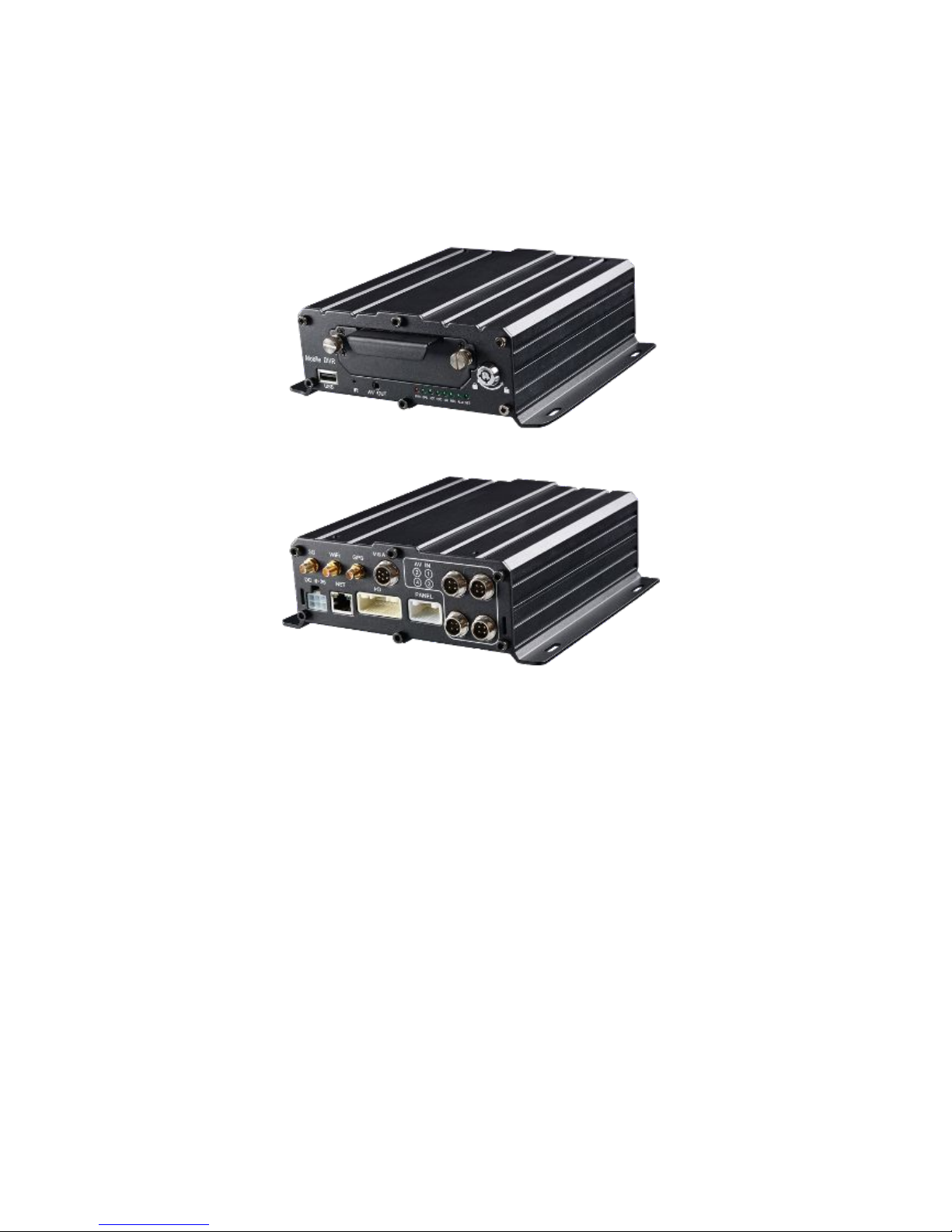
1.2. Appearance
Product appearance pictures are displayed as follows:
Page 9
- 8 -
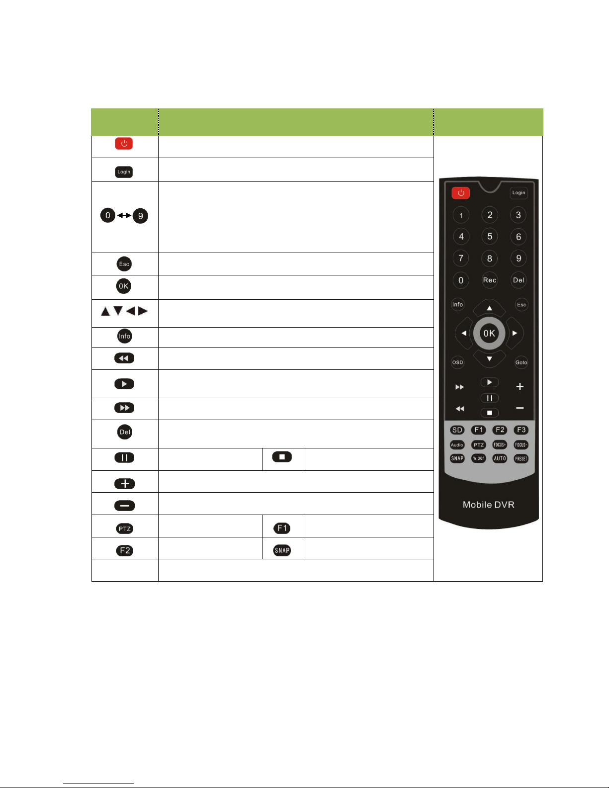
1.3 Remote Controller
Key Function Picture
Power and Standby Button,Reserved
To enter system settings.
[0-9] key:In the setting mode, 0-9 is used to select the
number of menu items. In playback mode, the key 1,2,3,4 to
select single channel playback,
ESC Button for 4-channel playback.
Delete Button
Return to the preview picture or previous menu
Enter button: button for setting system parameter,
selecting,,switching and playing.
Direction Key:up, down, left, right
Display system info under monitoring mode
Rewind button. In play mode, press REW button to
select 2/4/8/16/,Press play button return to normal
Play Button
Forward button. In play mode, press this button to select
2/4/8/16/,Press play button for return normal
Pause button Stop button
Playback Page\Forward to del param\Aperture larger Key
Playback Page\Back del param\Aperture reduce key
PTZ Function key Calling Shortcut
Quickly setup Snap pictures
[Others] Reserved
Page 10
- 9 -
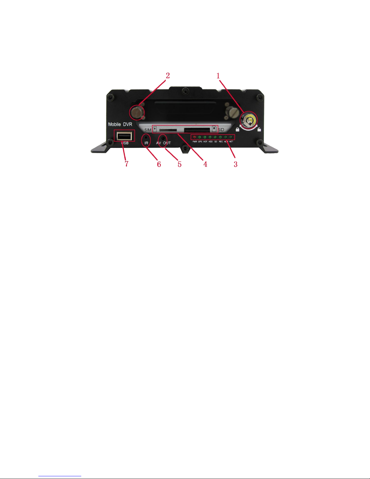
1.4 Fron tand Back Panel
1.4.1 Fron LED Indicators
1—HDD Lock, it’s used for unload hard disk.
(Device will power off automatically if power on when HDD lock is open)
2—HDD Fixed Screw . Please manually tighten screw after installing hard disk drive, to prevent HDD slip out ;
3— Status Indicator LED . Details as below :
PWR — Power Indicator LED. LED light means system has powered on.
GPS — GPS/BD Status indicator light. LED ON—Positioning success,
LED FLASH—In positioning ,LED OFF—No GPS Module.
HOT —Hard disk heating LED. LED ON—HDD is heating,LED OFF—HDD doesn’t open heating.
SD — SD card Indicator LED. LED ON—Card is recording,LED FLASH—Card exists but not recording,
LED OFF—Card does not exist.
HDD — HDD card Indicator LED.LED ON—HDD is recording,LED FLASH—HDD exists but not recording,
LED OFF—HDD does not exist.
REC — Video Recording Indicator LED.LED ON—In the recording
;
ALM — Alarm Indicator LED. LED ON — In the alarm ;
NET — Network Indicator LED. It changes based on dial-up connection status,details as below:
LED OFF—No communication module, LED INTERMITTENT FLASH—SIM CARD does not exist ,
LED QUICK FLASH (1:1) —Device is dialing, LED SLOW FLASH (3:1)—server connection is not OK ;
LED ON - server connection is successful.
4—SIM Card and SD Card Slot; ( When installation gap towards inside, metal touch spot face down )
5—Front audio and video output interface;(Reserved )
6—Infrared remote control receiving hole,It’s used to receive remote controller signal.
7—USB Interface ,It’s used to import or export data or upgrade;
** Status LED will alternate loop flash when device power on, it will quick loop flash when device is upgrading **
**** Built-in UPS,after device power off, PWR LED will be continuously on ten more seconds ****
Page 11
- 10 -
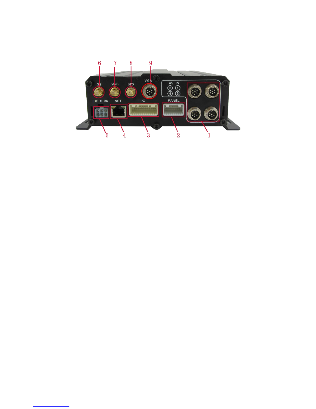
1.4.2. Back Panel IO Indicators
1— Video&Audio Input interface, 1-4Channels or 1-8Channels, with DC 12V output:
2—16 PIN Extension Port , With Video&Audio output interface、alarm input&output、serial port etc.
3—24 PIN Extension Port , With alarm input&output、serial port etc.More detailed definition see
addenda.
4—Rj45 Ethernet port , with print serial port, Can only connect 4PIN net cable when connect net
cable.
5—Power Input interface ,Input Voltage DC 8-36V,
Red cable connect power positive,
Black cable connect power negative;
Yellow line ACC signal cable.
6,7,8—3G、WIFI、GPS Antenna Port
;
9— VGA high definition output port.(Analog output port is standard definition output);
Attention:
Audio/Video analog output port is inside the device 16PIN PANEL port
When net cable directly connect to the device, only can use 4PIN definition cable, otherwise it will
lead device dead.
Page 12

- 11 -
1.5 Product Introduction
Before use,Please make sure that you have read this before installing and using .
Device Power Connection:
Just only connect DVR with power supply, the power of cameras and monitors are all supplied by DVR,
aviation connectors is built-in DC 12V output.
★
Use ignition switch to control video record delay time working
★
Red cable connect positive of the car storage battery, black cable connect negative, while yellow
cable connect independent ignition switch or independent positive;
★ switch connection(Indoor test usually use this way)★
Red cable and yellow cable together connect power positive of the car storage battery, while black
cable connect negative;
Camera connect AV IN, monitor connect BNC connector in AV out of PANEL.
If it’s not standard aviation connector, please use the aviation conversion line mentioned in the
addenda, Black side is DC 12V output, White side is Audio output, Yellow side is Video output;
Attention:
If the camera type and DVR setting mode(AHD HD/Analog/Mixture) don’t match, then it will show
“video lost”, in Mixture mode, 1,2CHANNEL is AHD high definition input, 3,4CHANNEL is analog
standard definition input;
In order to get better damping effect for HDD DVR, please horizontally install DVR .
Tips:
In the video preview interface, you can undertake the following actions :
Press F2 to enter Quick Setting, you can change the device number,server IP and port information;
Press LOGIN to enter the menu, direct input password: Administrator: 666666, User: 000000;
Press INFO to display the signal strength, dial-up connection status, hardware and software
versions, storage capacity, etc.;
Press 1.2.3.4 to enlarge the corresponding channel video, press 9 or ESC to return to four preview
videos.
Press the playback key Directly start the video playback;
Device No. and Phone number must be the same , they are all Platform device ID
Page 13

- 12 -
2. Main Functions
Main Sub-Item Instructions
Recording
Sub-System
Video Channel
5Channel video + Audio recording synchronously
;
Resolution
Support 1*1080P IPC, 4*720P(1280*720),4*D1(704*576),4*HD1(704*288),
4*CIF(352*288);Each channel is individually adjustable.
Image Quality 0-7 levels, 0 is the highest level.
OSD Overlays information such as date time and vehicle ID
Loop Rec Support SD card loop recording, loop cover previous video
Record Mode Timed recording, alarm trigger recording and manual recording
Preview
Support 1 channel and 4 channels preview. Support enlarge
video image when alarm trigger and video rear view trigger
;
Disk
overwritten
Space pre-allocated Support disks overwritten function.
Playback
System
Video Search Search video files anytime per day, type(n/a)
Playback
Support 1 to 4 channels playback.
Support forward and backward play at the speed of: x2 ,x4,x8,x16.
Support alarm spot search and time search.
GUI
Graphical User
Interface
Setup system parameters with the remote control.
Alarm
Input
8 channels electrical level alarm input for optional
Alarm linkage recording\Active request the intercom\One-key phone calling
functions,etc.
Output Max support 2ch level output
Optional
functions
GPS Positioning Built-in GPS/BD module: can sync record GPS information, trace replay.
PTZ Control Support Pelco-D protocol 485 PTZ remote/local control,preset.
Serial Expand
Support LED Advertisement Panel\Oil Sensor\POS\Bus Station Broadcaster\Car
OBD,ect.external devices.
G-Sensor G-sensor,Record vehicle real-time status.
TTS Voice
Broadcast
Support TTS voice broadcast function.
Network
Can expand WIFI module,support 801.2b/g/n, 801.2a/c
Built-in EVDO/WCDMA/TD-LTE/FDD-LTE,etc, 3G/4G module.
Others
ON/OFF System delay-time power on/off;
File System
DVR special file recording System Technology,Exclusive car record file
system,space pre-allocate,4ch single file Record,cyclic covering;To avoid the
storage of the media causes file fragments, with high reliability and high stability;
***** Above parameters any changes,please refer to actual product ******
Page 14

- 13 -
3. Parameter Sheet
Item Parameter
OS Linux
Language Chinese/English/Others (can be customized)
Video Compression H.264 Compression Mode
OSD Overlays information such as date time and vehicle ID
GUI
Graphical User
Interface
Can connect to external LED screen. Setup system parameters with the remote
control.
Video Record System
Video Input
(4CH 720P AHD input/4CH standard definition input/2CH high definition+2CH
standard definition mixed video input)+1CH 1080P digital video input ,aviation
connector.
Video Output
2CH CVBS+ VGA output for optional, 1.0Vp-p, 75Ω,Aviation,Support 1CH Full
Screen,4CH Screens
Preview
Support 1 channel and 5 channels preview,Support Manual/Alarm Trigger full
screen preview
Resolution 1080P/720P/D1/HD1/CIF, MAX:4 channels 720P+1 channel 1080P
Video Quality 0-7 levels, 0 is the highest level, 7 is the lowest level.
Video Standard
PAL: 100f/s , CCIR625 line,50field;
NTSC: 120f/s, CCIR525 line,60field;
CIF: 256Kbps ~ 1.5Mbps, 8 level video quality optional;
HD1: 600Kbps ~ 2.5Mbps, 8 level video quality optional;
D1: 800Kbps ~ 3Mbps, 8 level video quality optional;
720P: 4Mbps-6Mbps, 8 levels video quality optional
1080P:
Record Mode
The default setting is auto recording after power on. Timed recording, alarm
trigger recording and manual recording are supported.
Audio
Audio Input 4CH Aviation connectors + 1CH IPC input mixed Audio stream.
Audio Output 2CH,Front port is earphone port ,rear port connects to BNC connector.
Compression G.726 compression, 8KB/s speed
Alarm Input
8CH IO Alarm Input, 1CH AD input, pulse speed input; Support alarm linkage
function
Alarm Output
2CH Relay Alarm Output, Support the linkage acousto-optic alarm, cut off fuel
oil/power,etc
Communication Interface
3CH RS232, support extension device, such as POS machine, Oil Feul sensor, LED
advertising screen , etc.
2CH 485 interface, can connect PTZ,etc.
2CH CAN interface.
Page 15

- 14 -
Wireless transfer
Support Built-in 3G/4G network, WCDMA,CDMA2000,TDD-LTE,FDD-LTE...
Support Built-in/External WIFI,Compatible with GPRS,EDGE
Position Support Built GPS/BD Module,can make playback analysis of vehicle routing
G-Sensor Support G-sensor
Video
Storage
Storage
2.5’’ HDD+ SD Card,each max 2TB HDD + 128GB SD Card mirror recording to
protect data from loss
Upgrade
Support USB flash disk updating,SD card upgrade , OTA remote upgrade
automatically
File Format .264 General video format
File System Special FAT32 File System
USB
Front panel supports USB port, support USB flash disk upgrade to backup; hard
disk box USB port, can back up video data
Video
Playback
Video Search Search video by Record Time/Record Type etc
Playback
Max support 4CH Replay /Stop/Fast Forward/Fast Reverse at same time
Support x 2,x4,x8,x16. fast forward or fast backward play
Safety Management User/Admin 2 Levels Different Passwords , support screen lock
Extension
Functions
TTS Voice
Broadcast
Support the TTS Voice Broadcast function
Serial Port
Extension
Support kinds of Access Equipment such as LED Advertising, PTZ control, Oil Fuel
Sensor,etc.
Voltage &
Power
Consumpti
on
Power
Management
Adaptive wide power input, support Wide Voltage, Over-load、Over-voltage、
Short Circuit、Reverse Protection.Support Time Setting/Delay power off
Voltage Input DC:+8V ~ +36V
Voltage Output
+12V@2.5A,+5V@2.5A
Power-off
Protection
UPS Technology,All video information can be saved automatically when the
power is cut off, and make sure that all the files can not be damaged.
Power
Consumption
Normal Working <5W
Working
Environme
nt
Temperature -20℃ to +70℃
Humidity 20% to 80%
others
Size 200 (D)* 187(W)* 62(H) mm
Net Weight 1.9kg
***** Above parameters any changes,please refer to actual product *****
Page 16

- 15 -
4. Real-time video interface description
4.1 Real-time monitoring interface:
Real-time monitoring interface status icons are displayed as follows :
4.2 Various signal status icons as follows:
3G Signal status:
4G Signal status:
GPS Signal status:
WIFI Signal status:
Center connect succeed status:
SIM card Not Exit Status:
Page 17

- 16 -
Text scheduling real-time interface displays :
*******************************************************************************************
Preview screen, press the remote control - on - next - right, will lock remote control, there will be an underscore
prompts between the date and time;
Press the remote control - on - next - left to unlock. Video loss or reboot the device will unlock;
*******************************************************************************************
5. Operation Interface Setup
5.1 User Loading
When the password switch is set to “Off ”: The host start and press [OK] key, will direct access to the
main menu..
When the password switch is set to “On”: Move the cursor to "landing" column, Press [OK] key, then
can enter the main menu.
**********************************************************************************
The administrator default password is 666666 (or device number –before changed the password available);
User default password is 000000, only have query permissions;
**********************************************************************************
Page 18

- 17 -
5.2 System Main Menu
The main menu includes: Search, System setup, Rec setup, Network setup, Alarm setup,
Peripheral setup, System Tools, System Information, as below:
5.3 Search
Query menu includes: Record, Picture, Log, Dispatch, call records
Page 19

- 18 -
5.3.1 Video Search
**** Green color display indicates current day and time exist video file ****
“Search Date”: Press the number key to enter date, default is current date.
“Start Time”: Press the number key to enter date, default is 00:00.
“End Time”: Press the number key to enter date, default is 23:59.
“Record Type”: Press the [OK] button to select the query type: All videos \Alarm recording. Default is All
videos.
“Storage Media”: Press the [OK] button to select: all disks, disk 1, disk 2.
“Search”:Move the cursor to "Search" button, press the [OK] key to enter the search results interface.
Press the arrow keys to select the video you want, press the keys to quickly flip, press
to turn to first page or last page, press the play button to play the video, press [ESC] key to return to the
previous menu
Press the arrow keys to select "Home", "Previous", "Next", "Last" and press [OK] button to display the
next page information.
Page 20

- 19 -
5.3.2 Picture Search
This menu is mainly for searching the screenshot pictures.
Zoom up single full screen will auto screen capture by default , it will be triggered by the alarm linkage
or manually operate.
**** Pictures and device log all save in the second partition ****
5.3.3 Log Query
This menu is to query device operation and working log , you can choose the same type log via log categories.
When select a single log, press the keys to quickly flip over, and press to turn to
first page or last page.
Page 21

- 20 -
5.3.4 Dispatch
This menu is to query the device scheduling information, text messages, etc.
5.3.5 Call Records
This menu is to query log of device voice calls recording.
5.4 System Setup
Under System Setup menu includes: Power, time setup, user setup, terminal setup (menu setup and
modifying need to choose save to take effect)
5.4.1Power Management
This menu is to setup Power management modes and power distribution.
Page 22

- 21 -
"Power mode":press the number keys to select the type, the default is ignition mode.
"Delay Off": Press the number keys to enter the time, the default is 5 minutes, can be set to 1440
minutes
"Screen time”: Press the number keys to enter the time, the default is 60 minutes, can be set to 0-1440
minutes
"Power On": Press the number key to enter time, setup the timer start time
"Power Off ": Press the number key to enter time, setup the timer off time
" Layout": optional: Single, 2-channel, 4 grids, nine grids and other video channel layout
5.4.2 Time Set
This menu is to setup device parameters, such as date and time, etc.
"Date Type": Different date format for choosing.
"Date": Press the number keys to enter current date.
”Time Synchronization": calibration mode: GPS, NTP and other school models available.
Time Zone": Setup the time zone of the location of the device
"Timeout": optional remote control does not operate the exit time
“Real Time": Press the number key to enter the current time
After opening GPS time revision function, device will automatically collate the time based on corresponding
time zone when device starts every time.
Page 23

- 22 -
5.4.3 User Management
"Password Enable": You can enable or disable password authentication to access the menu.
Modify or setup password of users and the administrator by remote control.
**** ADMIN Pass : 666666, USER Pass : 000000 ****
5.4.4 Terminal Setup
By remote control input settings: device number, phone number, license plate number, license plate
color, chassis number, vehicle type, the provincial domain ID, the City ID, driver's license number,
authorization code, company name, telephone service, terminal type, manufacturer ID, terminal ID, the
device management (data in accordance with the Department of standards, Chinese input can use the soft
keyboard input)
Page 24

- 23 -
5.5 REC Setup
Recording setup menu includes: basic setup, Main stream, Sub stream, mirror Recording, time recording,
disk management(configuration and modification must select Save to take effect)
5.5.1 Basic Setup
This menu is to setup the basic video, audio and video parameters and can change into standard
definition, AHD high definition and mixed mode.
"Video Type": PAL / NTSC, press [OK] key to select.
"Record Mode": Auto / timer / alarm recording, press [OK] key to select.
"Audio Type": G726 audio format.
"Audio Gain": 1-20 gain level to select.
Page 25

- 24 -
"Alarm pre-recorded": pre-recorded alarm recording time of 0-60 seconds to setup, press number keys
to setup.
"Alarm delay": alarm delay recording time, 120-300 seconds to set up, press number keys to setup.
"Camera Type ": Can switch the status of standard definition , high definition or mixed camera input.
Attention :
If the camera type and DVR setting mode(AHD HD/Analog/Mixture) don’t match, then it will show
“video lost”, In Mixture mode, 1,2CHANNEL is AHD high definition input, 3,4CHANNEL is analog
standard definition input;
5.5.2 Mirror Record
When there is dual storage in device, you can choose one as a mirrored video memory. And setup the
recording parameters.
5.5.3 Main Stream
This manual is to setup the code stream and definition of video channel.
"Enable": open or close the channel of pre-recording function, press [OK] key to select.
"Resolution": CIF, HD1, D1 and 720P resolution for choosing, press [OK] key to select.
"FPS": 1-25 frame (P standard), 1-30 frame (N standard) channel recording frame rate for choosing.
"Image quality" setup video quality under different resolution, 4-speed adjustable.
"Audio" setup the audio recording on or off.
**** According to the storage space and quality requirements, the resolution of each channel and stream
can be configured individually ****
** The setting of the 5th channel code stream need pre-allocate in the IP camera **
Page 26

- 25 -
5.5.4 Sub-stream
This menu is used to set the parameters of the transmission stream.
"Resolution" Setup the transmission resolution, press [OK] key to enter.
"FPS" Setup the transmission time frames, press [OK] key to enter.
"Image quality" setup transmission quality grade, press [OK] key to enter.
**** Sub-stream is the code stream which device upload via 3G/4G, high definition main code stream
can be chose in the client-side platform ****
5.5.5 Time Record Setup
Setup the timer recording time periods, everyday can be set to two periods.
Move the cursor to "Timing Recording" and press [OK] button to set up the following timing list.
**** Timer recording start time is before the end time. ****
Page 27

- 26 -
5.5.6 Disk Management
When there are multiple disks, they can be set up recording parameters and priority grade.
"REC": Setup main video or sub video in disk.
"Pri": Setup the priority of different memory, enabling loop recording, function missing video recording.
5.6 Network Set
Including: Center setup,Local Network ,3G setup ,WIFI setup ,FTP setup and IPC setup.
5.6.1 Center Setup
Set Server IP and Port ;
Page 28

- 27 -
“Monitoring Center”:Set 3G /4G Video Center IP or domain,port information etc,
“Network Type”:Set 3G network type, IP address/Domain optional;
“Center IP”:3G Server IP/Domain setup. Press right key to enter keyboard interface,input the numbers
via remote controller,then press [OK] for setting,;
“Port”:Communication port between 3G device and Server,must be same with server configuration;
“Group2 Center”:BD Server IP/Domain/Port Setup,make device can hang on BD server;(Chinese
Government Server)
“Network Type”:BD Server network type,IP/Domain type optional;
“Center IP”:BD server IP/Domain setup,Press [OK] for setting;
“Port”:Communication Port of Device and server,port setting must be same with server configuration;
Group3 and Group4 are kept for reserve.
In “ Info ” interface, W connected : it means device connected server already; B connected : it means
device connected ministerial standard platform already, Connected : it means two platforms both connected
device successfully.
5.6.2 Local Network Setup
Device Local Network setup
Page 29

- 28 -
“IP”\“Mask”\“Gateway”\ “DNS1” \“DNS2”\“MAC”:IP,Mask,Gateway,MAC setting for LAN network testing.
Attention:
When net cable directly connect to the device,
only can use 4PIN definition net cable (please
see more definition in the addenda), otherwise it will lead device dead.
5.6.3 3G/4G Setup
3G/4G Network Configuration
“Enable”:3G/4G On/Off Setting,Press [OK] for choosing;
“Type”:3G/4G Type setting,WCDMA\EVDO\TD-SCDMA\TD-LTE , FDD-LTE, press [OK] for choosing,
“APN”:Set 3G/4G APN,Press [OK] Input, enter into input page to set the information
“User”, “Password”:SIM Card Network Operation User and Password, Press [OK] for setting ;
5.6.4 WIFI Setup
Page 30

- 29 -
“WIFI-EN”:WIFI On/Off Setting,Press [OK] for choosing;
“Encr-EN”: WIFI encryption ON/Off Setting,press [OK] for choosing;
“Au-Mode”: WIFI Authentication mode setting,Please choose same one with your router,
“Enc-Type”: WIFI Encryption type setting,Please choose the one same with your router,
“IP”\“Mask”\“Gateway”:WIFI IP/Mask/Gateway setting
“SSID”: Input Your WIFI SSID,
“PWD”: Same with your WIFI password,
**** According to the specific configuration of WIFI network environment, please pay attention to
check the accuracy of the characters and the IP address ****
**** IP address set by WIFI and local network can not be in the same network segment ****
5.6.5 IPC Setup
Through IP Setup, Maximum configuration can support 1CH 2MP IPC real time transfer data and video
recording.
“Enable”: IPC Access On/Off Setting, For now only support 1CH IPC video&Audio input;
“Protocol”: Select each manufacturer camera ONVIF protocol, support mass customized production;
Type1: HIKVISION. When choose HIKVISION IPC PTZ , need to choose Type1; when choose HI
KVISION IPC camera, need to choose Type2;
Type2: XiongMai. Type3 and Type4 are for test custom reserved.
After choosing Protocol, then directly input Camera IP, UserName and UserPWD has been set
based on RTSP protocol, DO NOT modify it into login password.
**** When need connect IPC, the connection type should be change into Peripherial ****
**** the IP address of IPC should be the same segment with local IP ****
Page 31

- 30 -
5.6.6 FTP Setup
FTP Server setup for OTA Automatically grading when new firmware upgrading in FTP Server;
.
“IP Address” “Port” “ User ” “ Password”: Please do configuration of IP Add, port,user,password
according FTP Server Setup.
5.7 Alarm Setup
Including: IO/Speed/Temperature/Accel/Voltage/Output
5.7.1 IO Alarm
Each channel alarm enable/level/time delay/Linkage information setting;
Page 32

- 31 -
“Enable”:Alarm Trigger enable on/off and alarm type, press [OK] for changing;
“Level”:Choose Alarm trigger level,High/Low Level optional,press [OK] for optional;
“ Delay”:When alarm trigger,if need delay alarm trigger,time can be set to reduce error alarm, press [OK]
for changing;
“ Record”:Record set when alarm trigger, press [OK] for changing;
“ Linkage”:Linkage set when alarm trigger, press[OK] for changing;
“ Preview”:when alarm trigger the Channel will be full screen for preview,can realize Car Reversing,Door
open alarm etc, Press [OK] for changing;
“Alarm keeping”:Set the alarm triggering time delay, which can be used to reduce misinformation.
If there isn’t the specific function option you wanna display, you can choose the custom function, press
“INFO” to modify the display name by custom.
Attention:
“Enable” function cannot be repeated, otherwise it will lead to abnormal alarm report.
Page 33

- 32 -
5.7.2 Speed Alarm
High/Low Speed or illegal driving alarm can be set.
.
“ Speed Source”: The method to get speed, GPS/Pulse Signal Optional, Press [OK] for changing;
“ Pulse Number”:Must set Pulse factor for the standard if using Pulse to get car speed information,press
Numbers for changing,can search vehicle data or constant speed by several times setting for a certain
number
“ Unit”: Driving Speed Unit,Press [OK] For Changing Setting
“Timeout Parking”\“Low Speed Alarm” \“Low Speed Warning”\“High Speed Warning” :by Enable to
open or close alarm function,Level setting for alarm trigger response speed and time; Delay: alarm
time ;Record: if recording when alarm appear;Linkage: When alarm occurs if linkage with alarm output;
5.7.3 Temperature Alarm
Low/High Temperature Parameter Setting.
Page 34

- 33 -
5.7.4 G-sensor
SET G-sensor information of alarm threshold and linkage actions.
Before configuration, need to calibrate the current state first, then modify the alarm threshold.
5.7.5 Voltage Alarm
Low/High Voltage alarm.
Voltage abnormal delay shutdown: it means the voltage is kept below 8V, automatic shutdown time, this
can effectively protect the battery, to avoid abnormal conditions caused by the battery voltage shortage,
prolong the service life of the battery.
5.7.6 Motion Detection
This menu is to set the image changes and the parameters of the object in the video pictures.
Page 35

- 34 -
“Threshold ”: Main is area alarm percentage, generally set 1 or 2, representing 1% or 2% area change
images move,it will trigger motion detection alarm.
“Sensitivity”:0-7 levels, 0 is the highest level, 7 is the lowest level. Generally suggest to set 1, the bigger
number you choose ,the lower the sensitivity will be, then it’s not easy to alarm as well.
Specific configuration parameters can depend on actual situation of the scene, such as illumination,
detection area range and so on, to achieve the optimal effect.
5.8 Peripheral Set
PTZ/OIL/LED etc Serial Setting
Page 36

- 35 -
5.8.1 PTZ
PTZ Camera parameter configuration
“ Protocol Type”:The Protocol of PTZ Camera support option,Press [OK] for changing;
“ ADD Code”:choose PTZ Camera Address code,press Number for changing;
“ Preset”:Choose PTZ Camera Preset code,press number for changing;
** When using remote controller to control PTZ, after configuring parameters, need to zoom in single
screen first, then press PTZ ,then use the direction keyboard to control **
5.8.2 Oil
Reserved oil set menu, can be set on the serial port currently
5.8.3 Serial Port Set
External Device parameter setting, can connect LED Advertisement/TTS/Oil/Sensor/POS etc ;
Page 37

- 36 -
“ Peripheral”:The external device type option,press [OK] For Changing;
“ Baud Rate”:Choose Baud Rate of external device,press [OK] for changing;
“ Data Bit”: Choose the Data bit of external device, press [OK] for changing;
“ Stop Bit”:Choose the Stop bit of external device, press [OK] for changing;
“ Check Bit”:Choose the Check bit of external device, press [OK] for changing;
“Control Bit”: Choose Control bit of external device, press [OK] for changing;
**** Just need to choose function and modify the baud rate, other options can keep default ****
5.9 Tools
Including: Phone Call,Format,Parameter/Tel Book
5.9.1 Call
Call Phone Number ( SIM Card must support Phone Calling function) , press [OK] to enter Dialing
interface
s
Page 38

- 37 -
5.9.2 FORMAT
Format Disk choice, device will reboot disk after confirming, log and pictures and other related info will
be reserved.
Attention:
DISK 1 is SD Card , DISK 2 is HDD.
Device will format automatically when it starts, new HDD or SD card, can be formatted on the computer,
in general, it doesn’t need format disk in DVR by manual.
5.9.3 Parameters Management
Page 39

- 38 -
“Import”:Import parameters from HDD or SD Card to current device.Import the system configuration
parameters which has set up and restore the factory settings to the factory states
“Export”:Export current device parameters to HDD or SD Card;
“Default”:Default to factory setting; This operation will clear all the setting on the device.
If quantity Devices with same setting,please using Parameter Export/Import for configuration,
after setting one device, export these parameters to HDD or SD Card then import to other rest devices
to be fast setting.
5.9.4 Tel Set
Can input detail phone number and query
5.10 System Info
System Info have 3 parts for detail information;can view by menu or Press INFO:
Page 40

- 39 -
Page 41

- 40 -
5.11 Mainconfiguration instructions
SIM card dial-up parameters should be set in
3/4G Setup, customers can consult APN and other
related parameters from SIM card operators.
After mounting SD card, SIM card and antenna,
press “info” button to check the signal strength,
dial-up state, the server connection state,Next page
show disk and RS232 status; Here shows positioning,
the connection is successful below.
If need to change the server, press F2 to enter
quick settings page , device number and mobile phone
number are the same to set as the device ID, the
monitoring center can change the IP for the server;
4CH DVR can switch camera input type in Video
Recording Set—Basic Record Reset,choose AHD or
Normal camera, after saving it will reboot
automatically; In Mixture mode, 1,2CHANNEL is AHD
high definition input, 3,4CHANNEL is analog standard
definition input;
In video preview interface, directly press ,
can make video search replay.
Page 42

- 41 -
6. Device Installation
6.1 Power Cable Connection
Attention
1. The recorder is DC power supply; please attention the positive and negative polar.
2. The voltage is 7V~48V.Do not insert voltage that beyond this range. Under low voltage the recorder
doesn’t work, under high voltage will be harm to the recorder.
3. Please make sure the recorder is connect with the car power directly. Do not connect with the generator,
the instantaneous voltage will harm to the recorder.
4. The initial power will beyond 30W when the DVR connect with the Camera (the consumed power is
different due to the connect with different device, the power supply must beyond 30W.
5. The power cables must can stand beyond 60W.(For example, when
the output voltage of car is 12V,the power cables must can bear 5A or more.
6. Please put the cover on the cables, the cover must be wear-resistant, heat-resistant, water-proof,
grease-proof, in case of short circuit and open circuit.
7. Please install a 10A fuse box near the battery output positive polar for fear of the short circuit will damage
the power supply.
Page 43

- 42 -
6.2 Audio/Video Interface Definition
The device support channel AV1~ AV4.The aviation joint can adapt severe environment in
the vehicles;
The power in the rear panel, IO and other PIN of the interface below:
Extension interface PIN order refers to Figure 24PIN, 24PIN and 16PIN detailed definitions
are as below:
Page 44

- 43 -
6.3 Alarm In/Output Connection Mode
Device have 8CH Alarm Input Interface, 24 PIN I/O Interface Definition is IN1 - IN8 .
Alarm input usually using High Level to trigger, connect SOS button,Kinds of vehicle driving status such
as: Braking,Turning,Door open etc;
The following is the brake detection diagram. When the braking vane is down, the device can detect the
high level or the low level.
Alarm Output is Relay Switch output,can connect Acousto-Optic alarm,Remote Oil/Power cut off etc, if
for high power device need connect external relay
The alarm output diagrams are as following
6.4. Disk pre-allocated technology instructions
Hard Disk pre-allocated technology means, the multiple channel videos will only write in a single
video file. Features: 1. it avoids repeatedly wipe cause file fragmentation; 2. Avoid long distance
repeatedly reading and writing to the hard disk magnetic read; 3.Protect FAT table and catalogue area,
reduce the disk failure.Through the technology above can ensure the reliability and stability of the
disk, prolong the life of the SD card / hard disk, video data security;
Hard disk drive will be automatically created two partitions, respectively, used to store system logs
and video files, including rec_dir,means video disc, multiple channels video only create into a video file.
Attention
After new hard disk insert into DVR, when start in the first time, DVR will automatically format
storage device to pre-allocate the storage space.The loading time of storage device status display
normal need 2-3 minutes, the capacity of a single video file and disk is fixed;
Page 45

- 44 -
6.5. Hard Disk box installation instructions
1. Turn over the hard disk box, dismantle 2 screws in the side and underside,as shown <Figure 1>.
2. Install 4 screws on 2.5inch hard disk, remove the hard disk box from one side bracket, as shown in
<Figure 2>.
3. First connect SATA flat cable with hard disk ,then insert the four braces into both sides of the bracket
damping rubber ring hole,then fix two screws on the bracket,as shown <Figure 3>.
4. After installing hard disk box, fixed screws tightened hard disk, and lock the hard disk lock.
Attention :
If the storage door is unlocked, DVR will power off automatically in 3minutes.
Figure 1
Figure 2
Figure 3
Page 46

- 45 -
7. FAQ
Q:When Device issue appear,you are confused on how to solve it.
A:Check Device Item No & Firmware Version,sent back to us with detail description of issue.Our
Technical Team will handle it.
More detail you described,easier for us to solve it quickly.
Q:Video Output Lost
A:1.Check situation of DVR:Device Input Power;Power Cable Connection;GND Connect to
battery;fuse;RED & Yellow Cable of Power must connect together;
2.Check the Screen Power or Check if the Screen change to related AV Channel;
3.Check the connection of Video Output & Screen Cable;
Q:Device keep Rebooting
A:1)Check working power,if low power device will keep rebooting;
2) HDD/SD Card error, remove storage device and turn on device checking;
Q: If the video input interface of the device and camera is different.
A:The DVR is using 4 needle type port, the camera is BNC port or Aviation, if it is different, please
use the X-over to connect, or connect according to the DVR Line sequence definition
Q:Device on with HDD but not recording;
A:1)Check SD/HDD if format;if not please enter Main GUI--System Set--Format,format HDD/SD
Card;
2)If close Recording ,or set Timed Recording mode, if yes it won’t recording if not the time set
3)If the HDD is connect well, if the HDD/SD light is on.
Q: Video files lost, or there is no video files at a certain period time.
A: 1. Analysis the lost video and ensure the lost time period.
2. Confirm if the DVR was opened at that time, such as crashed midway park, loading and
unloading ect. And the device didn’t set the delay recording
Q: Can not control the Car PTZ, can not rotate to all direction.
A: If the agreement and Baud rate of the PTZ is setting right,if the address code is corresponding, if
the video channel is setting to max when control the PTZ. Like if is control the first channel, then must
set the first channel image to be max.
7.1 GPS related FAQ
Q: With GPS but no GPS coordinate Information
A:1)Check if GPS module exist;
2)Check GPS Antenna connection,suggest install on the outside place with strong signal;
3)If testing in office, suggest put GPS Antenna out of window;
Page 47

- 46 -
4)If working environment not good will related to no GPS Information or wrong information;
Q:Deviation of GPS Location on Map?
A:The signal is effective if the GPS module has been positioning, there are so many reasons caused
bias, government restriction, permissible error, GPS signal break off, The actual satellite map error
occurred for the security, GPS Correction can solve the problem.
7.2 3G Wireless Module related FAQ
Q:If using 3G ,what should we concern?
A:1)Choose inside wireless module WCDMA,EVDO,TD-SCDMA, relative module setting is different
then SIM Card is different, please make sure the module is corresponding with the SIM Card.
2)If Server IP & Port set correct,if 3G signal strong for dialing;3G dialing successfully or not;
3)Check 3G Antenna connection,dialing will be failed if 3G signal too weak;
4)Check SIM Card 3G Flow
Q:When meet device offline or no video,what should be done first?
A:1)Press INFO key to enter the system Info page,check if SIM Card exist,3G signal and dialing
status,Antenna connection,Check SIM Card 3G Flow,change to a new SIM Card check again;
2)3G Signal strong but dialing fail,check if center IP & Port set correct;
3)Check if Device ID already be occupied;
Q:3G Signal is intermittent, video get stuck ?
A:At present, signal coverage of the WCDMA and EVDO is very wide, but still there are some
mountain area signal is weak, this will influence. Then check if the frame rate in Sub-stream setting is
too high.
Q:WIFI Signal 60/100,connect failure;
A:General condition, connection is no problem when the signal intensity up to 60/100 if WIFI setup
are right. If the device can not be found in LAN, then you should check if setting SSID and password, IP
Address, besides, check the Encryption Type and authentication mode if setting according to
requirements.
7.3 Client Software FAQ
Q:Device working but can not see Vehicle and video on client software
A: 1)Check if Center Server running and device Number if using;
2)Check Server IP and Port parameter setting;
3)Check is using 3G or WIFI for connecting, if 3G check the 3G Model WCDMA or EVDO and related
SIM card,3G antenna connect normally/APN setting/Center No. setting;
If it still can not work,please offer the most detailed information to us for technical support
Q:Device Online but can not see video
Page 48

A:1)Please set Low Sub-stream,when sub-stream set high it will effect the transmission because of
the network;
2)Network environment not good;
Q: Device works well in the Client, but cannot see the video a period time later.
A:1.Check if connect to server successfully on device, if dialing probably SIM Card no 3G
Flow,change another SIM card for testing;
2.Check if Device Number be changed,if yes,need add device to server again;
3.If still can not view video after previous 2 steps,please check if 3G module error;
7.4 Other related questions
Q: Video Lost in certain channel?
A: Possible reasons are as follows
1. This channel has no video input
2.The camera of this channel breaks down or work abnormality
3.If the camera takes an electricity power from the equipment directly, may be the
equipment’s electric voltage isn't enough to make camera work as usual;
d) The cable that links this channel has problem
Q: Can’t playback files on PC successfully?
A: Possible reason is as follows:
1.Have never chosen a record file or document path; please choose the path that records file first
before playback.
Q: Remote control not works?
A: Probably of the reasons are as follows:
1.The remote control didn't pack battery;
2.2.The remote control damages;
3.Device damages.
Q: During playback, the map doesn't show?
A: Possible reasons are as follows: Net cable did not connect to PC; Net works, but the computer
can not get to the Internet;
Q: When SD card and HDD records, How is the record coverage?
A: SD card and HDD will record circularly for each other. When they are full, they will delete the
original video records respectively.
2016 TTI All rights reserved. TTI is a registered trademark and the TTI logo are trademarks
of TTI Inc. All other
trademarks mentioned herein are property of©
their respective owners. Specifications are subject to change without notice.
Tel:
+1 (604) 473-7758
www.tt-i.info
 Loading...