

TTHERM GEO TVA series, TVT series Installation & Operating Instructions Manual

Single and Two-Stage
Packaged Geothermal Heat Pump
Installation & Operating Instructions
Models: TVA/TVT-***
Application
Forced air Geo source installation
Equipped for optional AUX EL strip heat (controller included)
Dual Heat, LMC (load management control), etc. – add option TT-INT
3-Phase Models
Domestic Water Heater, Desuperheater
Note
Tested to UL Standards 1995 and CSA Standards C22.2
Also see and use GI102
Energy Star promotes the desuperheater and it is offered as an optional item for
all TTHERM GEO™ heat pumps. Our exclusive GEO Logic™ control system
optimizes the operation of a desuperheater, operating the systems only when
there is adequate energy available to provide heat to the domestic hot water.
However, to maximize the times the desuperheater aides in providing domestic
hot water, a hot water preheat tank is suggested.
The GEO Logic control board has various required setup adjustments, see Field Setup section.
TTHERM GEO heat pumps leave the factory setup to operate on an open loop. See Open Loop
Solenoid section.
DO NOT DESTROY THIS MANUAL. PLEASE READ CAREFULLY AND KEEP IN A
SAFE PLACE FOR FUTURE REFERENCE BY A SERVICE TECHNICIAN.
Model Number:____________________________
Serial Number:_____________________________
Installing Contractor:________________________
Important information
12/06/2012 GI202

Table of Contents
Introduction 1
Safety Considerations 2
TTHERM GEO Heat Pump Configurator (GC002) 3
Mechanical Specifications 4
Electrical Data 6
Duct System and Blower 7
Duct Sizing Chart 8
Product Dimensions 9
Installation Requirements 10
Mechanical Installation Overview 11
Mechanical Installation Source Water 12
Antifreeze 15
Open Loop Solenoid 16
Converting to Right Hand Return 18
Optional Electric Strip Heat (AUX EL) 19
Desuperheater, Domestic Hot Water (SWH) 20
Condensate Drain 22
Electrical Installation 23
GEO Logic Controller 24
Add-On Option and Accessories 25
Field Setup Overview 27
Dual Fuel/Utility Control 29
Operation Indicators 30
Power On, Start Up 35
Operational Tips 37
Preventative Maintenance 40
TVT & TVA Operating Conditions Tables 41
Troubleshooting 45
Drawing GR201 p1 – Water to Air Heating Mode – refrigerant circuit 48
Drawing GR201 p2 – Water to Air Cooling Mode – refrigerant circuit 49
Drawing UAW553 – Electrical Diagram 50
Warranty Information – GX002 51
12/06/2012 GI202

Introduction
Geothermal heat pumps are able to heat and cool spaces with efficiencies exceeding 350% by taking advantage
of solar heat stored in the earth’s crust and the earth’s relatively stable temperatures. In the winter time, heat is
moved from the earth into the home and concentrated using a refrigeration system. Since the heat already exists
in the soil, the cost of operation of the geothermal heat pump is, in effect transportation cost for the free heat. In
the summer, heat is removed from the home by reversing the refrigeration process and sending heat back out
into the earth. A geothermal system consists of an earth source (either open loop or earth loop heat exchanger),
a geothermal heat pump containing the refrigeration system and a ductwork system for delivering the
conditioned air to the individual rooms. To learn more about geothermal heating, please visit our web site at
www.tthermgeo.com
This is a prewired package system with the necessary controls for various forced air heating applications. The
GEO Logic control uses a standard, multi-wire heat pump room thermostat to initiate and terminate all heat/cool
functions. There are various temperature sensors, pressure sensors, water flow switch, etc. which continuously
monitor the heat pump system. The interaction of these sensing components, room thermostat requests, and the
various heat pump refrigeration components plus optional AUX electric element heater are all controlled by an
integrated microprocessor system (GEO Logic). The various setup conditions for this microprocessor based
controller determine the application and geo product series. These setups are initially programmed by the
factory, but special PC software and cable are available for reprogramming as required for controller
replacement and/or other options which may apply to the specific installation. See Additional Equipment
Concerns, Field Setup or Programming, Operation Indicators, User Instructions, Control Sequence, and
Troubleshooting sections within this manual for further details on the GEO Logic control.
An optional T2-TT-INT-1 plug-in module is available to properly handle other applications with utility load
control, backup furnace, backup boiler, dual fuel, etc. In addition to the compressor and AUX heater, proper
operation of the forced blower and control of the external pumps are also operated with this optional module.
Moving and Storage
Units should be stored in original packaging in a clean dry area. Store and move units in normal upright
position. Do not stack units. Transport in vertical position only.
Initial Inspection
Be certain to inspect all cartons and crates as units are received before signing the freight bill. Verify that all
items received have no physical damage. Report any damages or shortages on the freight bill. The purchaser is
responsible for filing the necessary claims with the carrier. Concealed or hidden damages not discovered until
removing packaging must be reported to the carrier within 15 days of receipt.
Unit Location and Mounting
Locate the unit in an indoor area where the ambient temperature will remain above 45°F [8°C]. TTHERM GEO
provides 3 removable panels for ease of servicing; front (2), right and left bottom. This unit is zero clearance
rated; however, allow enough room to remove panels for service and maintenance. We suggest setting the unit
on a sound vibration pad, see accessories price sheet, part # E2-0122. Water supply should not be hard plumbed
directly with copper or PVC pipe as this could transfer any vibration to living space. Consider using Hose Kit
part # L3-0015B to minimize transferred vibration.
Please read and understand conditions associated with proper installation, unauthorized changes, and POWER ON
procedures.
Warranty Statement
See the last page of this manual for detailed limited warranty coverage explanation.
12/06/2012 1 GI202

Safety Considerations
WARNING
BEFORE PERFORMING SERVICE OR MAINTENANCE OPERATIONS ON A SYSTEM, TURN OFF
MAIN POWER SWITCHES TO THE INDOOR UNIT. IF APPLICABLE, TURN OFF THE ACCESSORY
HEATER POWER SWITCH. ELECTRICAL SHOCK COULD CAUSE PERSONAL INJURY.
Installing and servicing heating and air conditioning equipment can be hazardous due to system pressure and
electrical components. Only trained and qualified service personnel should install, repair or service heating and
air conditioning equipment. Untrained personnel can perform the basic maintenance functions of cleaning coils
and cleaning and replacing filters. All other operations should be performed by trained service personnel.
When working on heating and air conditioning equipment, observe precautions in the literature, tags and labels
attached to the unit and other safety precautions that may apply, such as the following safety measures:
Follow all safety codes.
Wear safety glasses and work gloves.
Use a quenching cloth for brazing operations.
Have a fire extinguisher available for all brazing operations.
Warnings, Cautions, and Notes
Throughout this manual there are warnings, cautions and notes containing various levels of important
information. Read all of these items carefully before performing any installation, servicing or troubleshooting
of the system.
Warnings are for any item which MUST be followed and failure to do so could result in serious injury or even
death and/or serious damage to the equipment.
Cautions relate to potentially hazardous situations or important practices which if ignored could cause minor to
moderate injury or cause equipment damage or performance problems.
Notes are used to indicate items of high importance but are not related to a hazardous situation.
12/06/2012 2 GI202
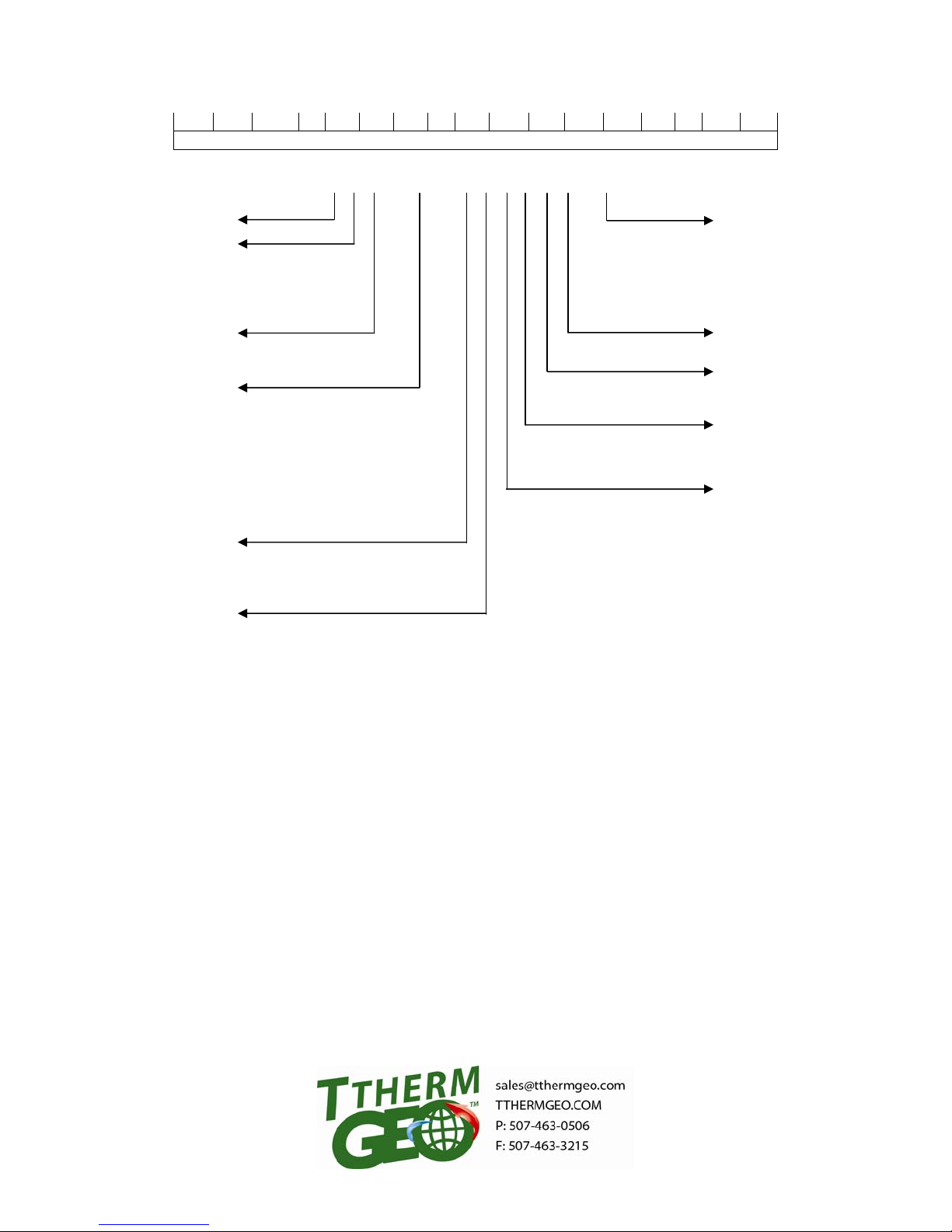
T V T - 0 4 8 - 1 C L D X 1 - X X
1 2 3 4 5 6 7 8 9 10 11 12 13 14
TTHERM GEO (1)
Unit Style (2)
C = Combo
H = Hydronic
S = Split
V = Vertical
Unit Type (3)
A = Single Stage
T = Two Stage
Nominal Tonnage (4, 5, 6)
Voltage Option (7)
Heat Exchanger Option (8)
M = Copper (Load) & Cupronickel
S = Stainless (THT only)
024 = 2-ton
036 = 3-ton
042 = 3.5-ton
048 = 4-ton
060 = 5-ton
072 = 6-ton
096 = 8-ton
120 = 10-ton
144 = 12-ton
1 = 208/230V, 1 Ph
2 = 208/230V, 3 Ph
3 = 460/480V, 3 Ph
C = Copper
N = Cupronickel
(Source)
TTHERM GEO Heat Pump Configurator
Model Number Digits
TVT-048-1CLDX1-XX
Auxiliary kW Option* (13, 14)
05 = 4.8 kW
10 = 9.6 kW
15 = 14.4 kW
20 = 19.2 kW
XX = None
*Can be factory or field installed
Vintage (12)
1
Miscellaneous Kits (11)
A = Soft Start Kit (Installed)
X = None
Desuperheater Option (10)
D = Desuperheater w/Factory
Installed Pump
X = None
Configuration Option (9)
L = Left Return (Standard)*
R = Right Return
C = Split Air Coil
X = N/A or No Split Air Coil
*Left return can be field converted to right return
10/12/2012 GC002
n
e
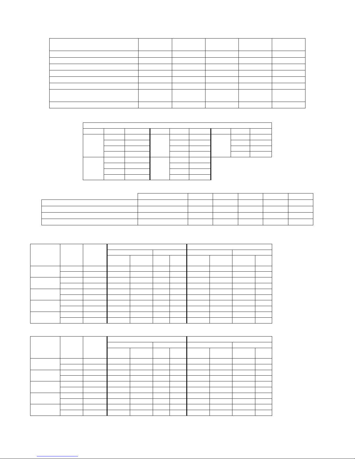
TVT - Mechanical Specifications – R410A Two-Stage Compressor
MODEL
TVT-024
(2 ton)
TVT-036
(3 ton)
TVT-042
(3.5 ton)
TVT-048
(4 ton)
TVT-060
(5 ton)
Coax & Piping Water Volume – gal .43 .65 .77 1.1 1.1
Source Temperature °F (min/max) 20°/120° 20°/120° 20°/120° 20°/120° 20°/120°
Nominal source differential* ° F (H/C) 3/12° 9/11° 10/11° 6/11° 6/10°
Factory Charge R410A 2 lbs. 14 oz. 4 lbs. 8 oz. 4 lbs. 8 oz. 6 lbs. 4 oz. 6 lbs. 4 oz.
Static Pressure – Nominal 0.3 0.3 0.3 0.3 0.3
Static Pressure – Design 0.5 0.5 0.5 0.5 0.5
Air Filter
Weight– Packaged (lbs) 440 480 490 503 530
HEAT EXCHANGER PRESSURE DROP TABLE
7/8 X 21 7/8
X 27 1/2
Water-to-Air (Source Side, Pure Water @ 68° F)
Model GPM PSID Model GPM PSID Model GPM PSID
4 1.2 (ref) 7 2.5 10 1.9
2-ton
6 2.7 (ref) 10.5 4.5 15 3.6
8 3.6 (ref) 14 7.0 20 5.8
3.5-ton
10 5.6 (ref)
6 1.8 (ref) 8 1.3
3-ton
9 2.4 (ref) 12 2.5
12 4.3 (ref) 16 4.0
4-ton
15 6.7 (ref)
PRESSURE DROP MULTIPLIERS
7/8 X 28 7/8
X 27 1/2
17 9.5
20 5.8
7/8 X 28 7/8
X 27 1/2
5-ton
7/8 X 27 1/2
X 37 7/8
25 8.5
7/8 X 27 1/2
X 37 7/8
Freeze Point (° F) 20° F 25° F 30° F 35° F 40° F
Pure Water Multiplier 32 1.00 1.00 1.00 1.00 1.00
Methanol 12.5%* Multiplier 16.2 − 1.25 1.21 1.18 1.15
Propylene Glycol 20%* Multiplier 18.4 1.39 1.35 1.31 1.28 1.24
Ethanol 20%* Multiplier 18.1 1.56 1.47 1.42 1.36 1.31
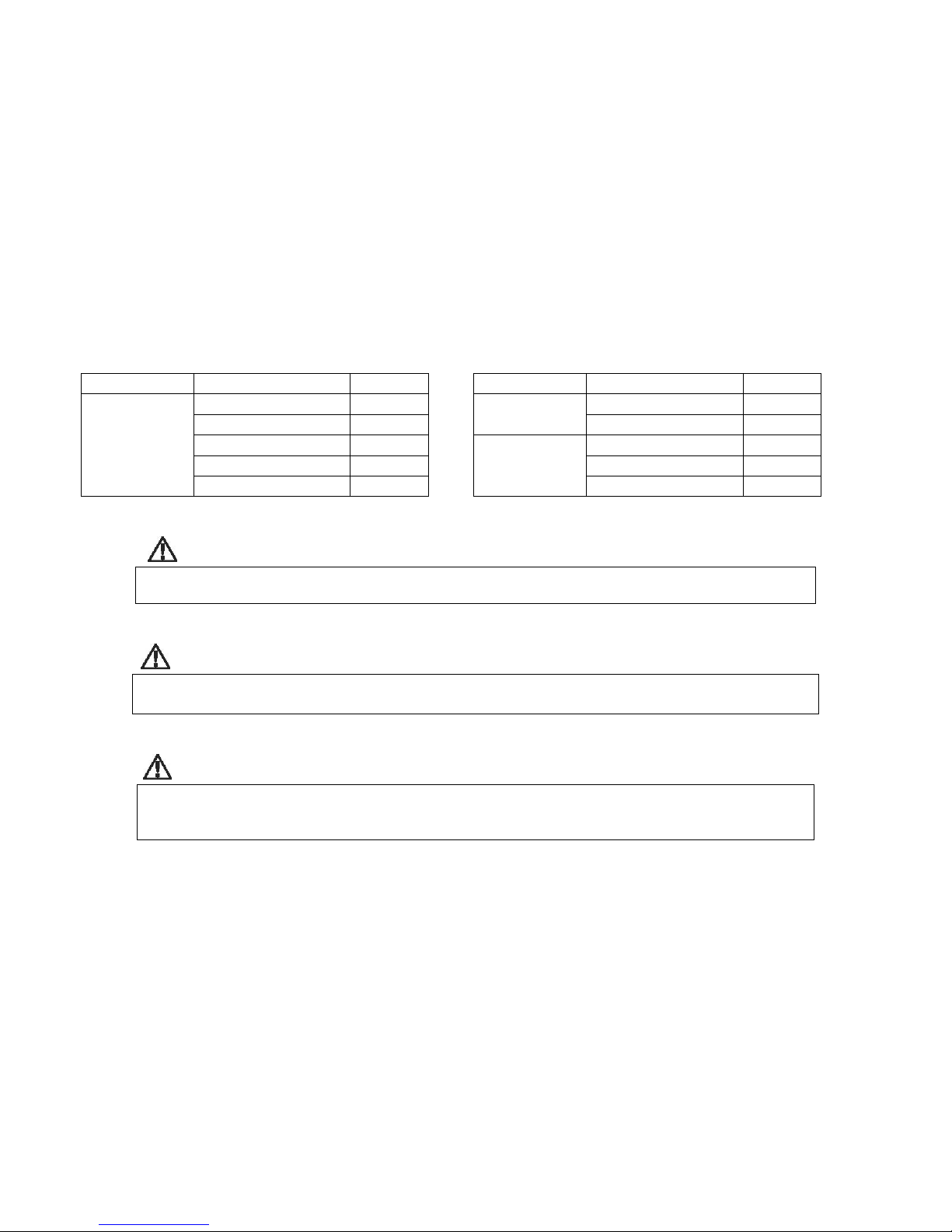
TVT - HEATING – ISO 13256-1 SPECIFICATION – ENERGY STAR
Model Stage
TVT-024
TVT-036
TVT-042
TVT-048
TVT-060
TVT - COOLING – ISO 13256-1 SPECIFICATION – ENERGY STAR
Model Stage
TVT-024
TVT-036
TVT-042
TVT-048
TVT-060
*By volume Feet of Head = PSI x 2.31
GWHP – Ground Water GLHP – Ground Loop
Source
GPM
50° F 68° F 32° F/41° F 68° F
Capacity
Btu/h
Blower
CFM
Temp
Rise
COP
Capacity
Btu/h
Blower
CFM
Temp
Rise
COP
FL 10 30.3 850 32 4.01 24.1 850 26 3.66
PL 10 23.0 725 29 4.20 19.9 725 26 3.98
FL 9 42.2 1200 34 4.05 32.8 1200 27 3.88
PL 9 30.5 1000 30 4.19 27.0 1000 26 4.04
FL 10.5 44.6 1312 33 4.07 35.6 1312 26 3.59
PL 10.5 31.5 1100 29 4.39 28.4 1100 25 4.07
FL 12 55.7 1500 36 4.01 44.4 1500 29 3.55
PL 12 37.3 1200 30 4.14 33.4 1200 27 3.67
FL 15 70.8 1875 35 4.08 55.5 1875 28 3.83
PL 15 53.1 1480 32 4.20 46.3 1480 29 4.07
1. Capacities are based on
GWHP – Ground Water GLHP – Ground Loop
Source
GPM
59° F 80.6° F 77° F/68° F 80.6° F
Capacity
Btu/h
Blower
CFM
Temp
Drop
EER
Capacity
Btu/h
Blower
CFM
Temp
Drop
EER
2. Stated Btu/h is the ISO
FL 10 36.5 950 22 24.1 32.7 950 20 16.1
PL 10 28.4 825 21 21.9 26.4 825 22 22.1
FL 9 47.0 1250 23 20.1 44.2 1250 22 15.9
3. Temp rise is based on sensibl
PL 9 35.1 1050 22 23.4 34.5 1050 21 21.3
FL 10.5 49.3 1400 22 19.3 47.6 1400 21 14.9
4. All ratings based upon
PL 10.5 36.4 1150 21 24.1 37.6 1150 20 21.1
FL 12 64.2 1600 23 20.1 58.3 1600 22 15.9
PL 12 47.7 1275 22 23.7 46.1 1275 22 21.5
5. Ground Loop Heat Pump
FL 15 75.8 2000 23 19.7 70.9 2000 23 15.2
PL 15 56.9 1650 21 23.3 55.7 1650 22 20.5
temperatures shown in headi
source is left group, return air
right group.
13256-1 formula adjusted,
actual HP supply energy
delivered is 2% greater.
only.
operation at lower voltage of
dual voltage rated models.
ratings based on 15%
antifreeze solution.
12/06/2012 4 GI202

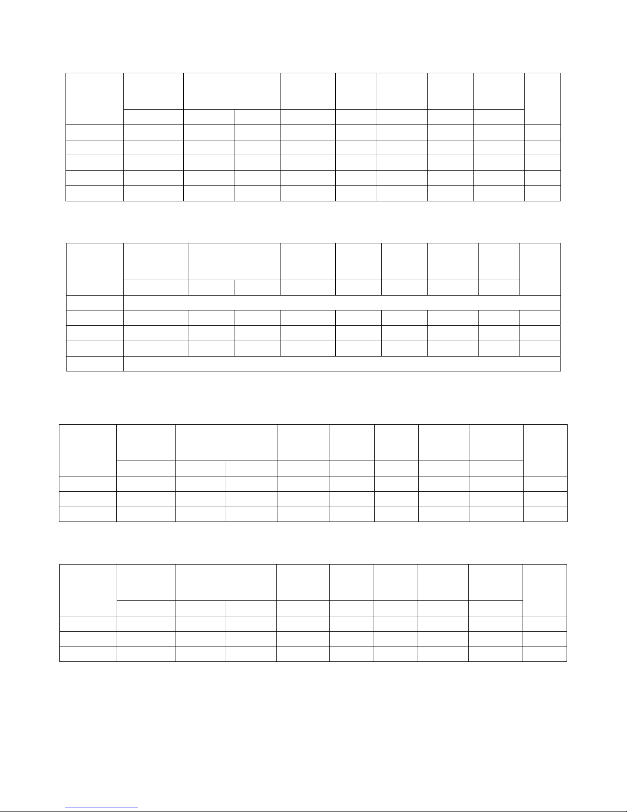
MODEL
TVA-036
(3 ton)
TVA-048
(4 ton)
TVA-060
(5 ton)
Coax & Piping Water Volume – gal .65 1.1 1.1
Source Temperature °F (min/max) 20°/120° 20°/120° 20°/120°
Nominal source differential* °F (H/C) 9/11° 6/11° 6/10°
Factory Charge R410A 4 lbs. 8 oz. 6 lbs. 4 oz. 6 lbs. 4 oz.
Static Pressure – Nominal 0.3 0.3 0.3
Static Pressure – Design 0.5 0.5 0.5
Air Filter
Weight– Packaged (lbs) 460 480 503
HEAT EXCHANGER PRESSURE DROP TABLE
7/8 X 28 7/8
X 27 1/2
Water-to-Air (Source Side, Pure Water @ 68° F)
Model GPM PSID Model GPM PSID Model GPM PSID
6 1.8 (ref) 8 1.3 10 1.9
3-ton
9 2.4 (ref) 12 2.5 15 3.6
12 4.3 (ref) 16 4.0 20 5.8
15 6.7 (ref)
4-ton
20 5.8
PRESSURE DROP MULTIPLIERS
7/8 X 27 1/2
X 37 7/8
5-ton
7/8 X 27 1/2
X 37 7/8
25 8.5
Freeze Point (° F) 20° F 25° F 30° F 35° F 40° F
Pure Water Multiplier 32 1.00 1.00 1.00 1.00 1.00
Methanol 12.5%* Multiplier 16.2 − 1.25 1.21 1.18 1.15
Propylene Glycol 20%* Multiplier 18.4 1.39 1.35 1.31 1.28 1.24
Ethanol 20%* Multiplier 18.1 1.56 1.47 1.42 1.36 1.31
1. Capacities are based on temperatures shown in heading, source is left group, return air is right group.
2. Stated Btu/h is the ISO 13256-1 formula adjusted, actual HP supply energy delivered is 2% greater.
3. Temp rise is based on sensible only.
4. All ratings based upon operation at lower voltage of dual voltage rated models.
5. Ground Loop Heat Pump ratings based on 15% antifreeze solution.
*By volume Feet of Head = PSI x 2.31
TVA – HEATING – ISO 13256-1 SPECIFICATION – ENERGY STAR
Model
Source
GPM
TVA-036 10 42.6 1200 34 4.28 32.7 1200 27 3.66
TVA-048 13 57.3 1500 35 4.10 45.2 1500 27 3.60
TVA-060 15 63.5 1875 35 4.10 50.7 1875 28 3.60
GWHP – Ground Water GLHP – Ground Loop
50° F 68° F 32° F 68° F
Capacity
Btu/h
Blower
CFM
Temp
Rise
COP
Capacity
Btu/h
Blower
CFM
Temp
Rise
COP
TVA – COOLING – ISO 13256-1 SPECIFICATION – ENERGY STAR
Model
Source
GPM
TVA-036 10 42.0 1250 23 22.9 38.1 1250 21 17.5
TVA-048 12 55.4 1600 24 22.2 52.6 1600 23 17.1
TVA-060 15 65.0 2000 23 21.4 63.8 2000 23 17.1
GWHP – Ground Water GLHP – Ground Loop
59° F 80.6° F 77° F 80.6° F
Capacity
Btu/h
Blower
CFM
Temp
Drop
EER
Capacity
Btu/h
Blower
CFM
Temp
Drop
EER
TVA – Mechanical Specifications – R410A Single Stage Compressor
12/06/2012 5 GI202
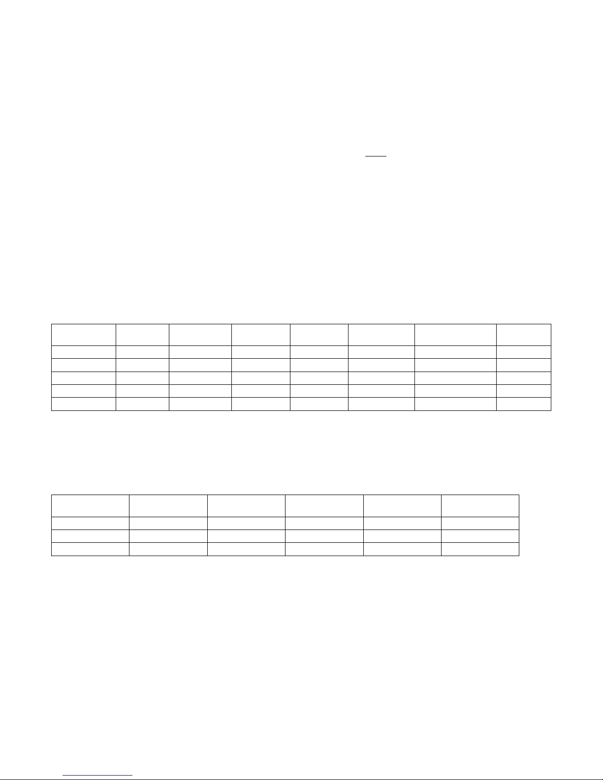
TVT - Electrical Data – Single Phase
Model
Loop
Pump
(Ext)
Total Min.
Voltage Compressor Blower
(60 Hz) RLA LRA FLA FLA FLA FLA Ampac.
Desup.
Pump
Max.
Fuse/
HAC
R
TVT-024 208/230-1 13.1 73 4.5 .15 4.4 23.1 25.4 30
TVT-036 208/230-1 17.9 96 6.1 .15 4.4 28.6 33.0 50
TVT-042 208/230-1 21.2 104.0 6.1 .15 4.4 31.9 37.2 50
TVT-048 208/230-1 27.1 152.9 6.1 .15 4.4 37.8 44.4 70
TVT-060 208/230-1 29.7 179.2 7.3 .15 4.4 41.6 49.0 70
TVT - Electrical Data – Three-Phase
Model
Loop
Pump
(Ext)
Total Min.
Voltage Compressor Blower
(60 Hz) RLA LRA FLA FLA FLA FLA
Desup.
Pump
Ampac.
Max.
Fuse/
HAC
R
TVT-024 NOT AVAILABLE
TVT-036 200/230-3 14.2 88 6.1 .15 4.4 24.9 28.3 40
TVT-042 200/230-3 14.0 83.1 6.1 .15 4.4 24.7 25.8 40
TVT-048 200/230-3 16.5 110.0 6.1 .15 4.4 28.3 32.5 50
TVT-060 NOT AVAILABLE
TVA – Electrical Data – Single Phase
Model
Voltage Compressor Blower
(60 Hz) RLA LRA FLA FLA FLA FLA Ampac.
Desup.
Pump
Loop
Pump
(Ext)
Total Min.
Max.
Fuse/
HACR
TVA-036 208/230-1 17.9 112.0 6.1 .15 4.4 28.6 33.0 50
TVA-048 208/230-1 26.4 134 6.1 .15 4.4 37.5 43.5 70
TVA-060 208/230-1 28.3 178.0 7.3 .15 4.4 40.2 47.2 70
TVA – Electrical Data – Three-Phase
Loop
Pump
(Ext)
Total Min.
Max.
Fuse/
HACR
Desup.
Pump
Model
Voltage Compressor Blower
(60 Hz) RLA LRA FLA FLA FLA FLA Ampac.
TVA-036 200/230-3 13.5 88 6.1 .15 4.4 24.2 27.5 40
TVA-048 200/230-3 17.6 123 6.1 .15 4.4 31.1 36.2 50
TVA-060 200/230-3 20.5 155 7.3 .15 4.4 32.4 37.5 50
12/06/2012 6 GI202
Duct System and Blower
Metal ductwork should be used, and flexible connectors are required for supply and return air duct connections.
All TVA & TVT THERM GEO units have flanges for connecting your supply plenum and return ductwork.
If the duct system is installed in an uninsulated space, the metal ductwork should be insulated on the outside to
prevent heat loss, absorb noise, and prevent condensation during cooling.
If the TTHERM GEO is connected to existing ductwork, the ductwork must
have the capacity to handle the air
volume required to unload the heat pump. Undersized ductwork will cause noisy operation due to high air
velocity, and poor operating efficiencies. Check the Duct Sizing Chart provided.
The TTHERM GEO heat pumps use a variable speed ECM blower motor. The GEO Logic controller determines
the speed of the motor based on mode and operation sequence. The blower speed can be fine-tuned to each
installation with the tweak switches described below.
The blower will not operate properly if ductwork is not attached. The ductwork provides static pressure to give
the blower motor a load to work against. All blower compartment covers must be in place for the heat pump to
operate correctly.
TVT - Blower CFM – Two Stage Compressor
Model G Cool Y Heat Y Cool Y2 Heat Y2 Cool Y 2 Heat + W2 E
TVT – 024 390 640 735 850 980 980 680
TVT – 036 515 900 965 1200 1290 1380 960
TVT – 042 575 985 1080 1310 1440 1500 1050
TVT – 048 660 1125 1235 1500 1650 1725 1200
TVT – 060 825 1400 1545 1875 2060 2160 1500
CFM Rounded
Y2 can be field fine-tuned or tweaked with a 4 position switch. The 4 positions are 0%, -6%, +6%, +12%
G can be field fine-tuned or tweaked with a 4position switch. The 4 positions are 0%, -6%, +6%, +12%
See figure 8 for location of 4 position switch
TVA - Blower CFM – Single Stage Compressor
Model G Cool Y Heat Y Cool Y Heat + W2 E
TVA - 036 515 1200 1290 1380 960
TVA - 048 660 1500 1650 1725 1200
TVA - 060 825 1875 2060 2160 1500
CFM Rounded
Y can be field fine-tuned or tweaked with a 4 position switch. The 4 positions are 0%, -6%, +6%, +12%
G can be field fine-tuned or tweaked with a 4position switch. The 4 positions are 0%, -6%, +6%, +12%
See figure 8 for location of 4 position switch
The “Y” tweak switch is the 2
The “G” tweak switch is the 3
Be very sure the tweak switches are set in their position indents.
nd
switch below the 10 pin thermostat socket.
rd
switch below the 10 pin thermostat socket.
12/06/2012 7 GI202

Duct Sizing Chart
Acceptable Branch Duct Sizes Acceptable Main or Trunk Duct Sizes
CFM ROUND Rectangular Round Rectangular
100 6” 4x8, 4x6
150 7” 4x10, 5x8, 6x6
200 8” 5x10, 6/8,4x14,7x7
250 9” 6x10, 8x8, 4x16
300 10” 6x14, 8x10, 7x12
350 10” 6x20, 6x16. 9x10
400 12” 6x18, 10x10, 9x12 10” 4x20, 7x10, 6x12, 8x9
450 12” 6x20, 8x14, 9x12, 10x11 10” 5x20, 6x16, 9x10, 8x12
500 10” 10x10,6x8, 8x12, 7x14
600 12” 6x10, 7x18, 8x16, 10x12
800 12” 8x18, 9x15, 10x14, 12x12
1000 14” 10x18, 12x14, 8x24
1200 16” 10x20, 12x18, 14x15
1400 16” 10x25, 12x20, 14x18, 15x16
1600 18” 10x30, 15x18, 14x20
1800 20” 10x35, 15,20, 16x19, 12x30, 14x25
2000 20” 10x40, 12x30, 15x25, 18x20
2200 22” 10x40, 15x25, 20x20
2400 22” 12x40, 16x25, 20x20
Table calculated for 0.05 to 0.10 inches of water friction per 100’ of duct. At these duct design conditions, along
with the pressure drop through the filter, the total design external static is 0.20 inches of water.
12/06/2012 8 GI202
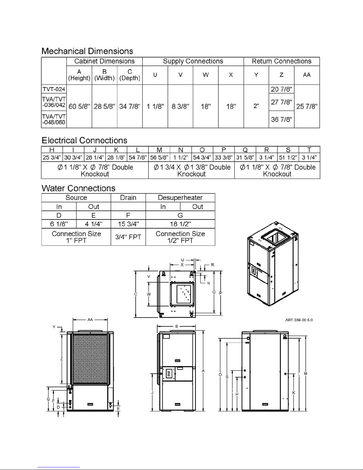
Product Dimensions
12/06/2012 9 GI202
Installation Requirements
1. All installation work must be performed by trained, qualified contractors or technicians. TTHERM GEO
sponsors installation and service schools to assist the installer. Contact TTHERM GEO at
sales@tthermgeo.com
WARNING
ALL ELECTRICAL WIRING MUST BE IN ACCORDANCE WITH NATIONAL ELECTRIC CODE
AND LOCAL ELECTRIC CODES, ORDINANCES, AND REGULATIONS.
WARNING
OBSERVE ELECTRIC POLARITY AND WIRING COLORS. FAILURE TO OBSERVE COULD
CAUSE ELECTRIC SHOCK AND/OR DAMAGE TO THE EQUIPMENT.
CAUTION
This unit can only be used for its intended purpose as described in this manual. Any internal
wiring changes, modifications to the circuit board, modifications or bypass of any controls, or
installation practices not according to the details of this manual will void the product warranty,
the safety certification label, and manufacturer product liability. TTHERM GEO cannot be
held responsible for field modifications, incorrect installations, and conditions which may
bypass or compromise the built-in safety features and controls.
2. If this is a Dual Fuel system, this product relates only to the addition to the furnace ducting system external
to the gas or oil force air furnace. The owner/installer assumes all responsibility and/or liability associated
with any needed installation of the gas/oil furnace, fuel system, flue, chimney, etc. Any instructions or
comments made within this manual (or factory phone assistance) relating to the gas/oil furnace are provided
as comments of assistance and “helps” only.
for upcoming dealer training events.
CAUTION
This unit shall not be operated (either heating section or blower) until the interior of the
structure is completed and cleaned. This also means all duct work must be complete with filter,
etc. Manufacturer’s warranty is void if this unit is operated during structure construction.
CAUTION
Hazards or unsafe practices could result in property damage, product damage, severe personal
injury and/or death.
3. All removed or discharged refrigerant must be recovered In accordance with local and federal statutes.
Should a compressor need replacing, the compressor oil is to remain with the compressor. Refrigerant lines
on the compressor must be capped during service.
4. Remember, safety is the installer’s responsibility and the installer must know this product well enough to
instruct the end user on its safe use.
At TTHERM GEO the safety of the installer and the end user is of highest priority. Remember, safety
is the installer’s responsibility and the installer must know this product well enough to instruct the end
user on its safe use. Professional installers should be trained and experienced in the areas of handling
electrical components, sheet metal products, and material handling processes.
12/06/2012 10 GI202

p
Mechanical Installation Overview
This TTHERM GEO series unit cannot correct airflow problems inherent within the duct work system. The
following items should be carefully considered and properly followed for all installations:
Examination of the existing forced air furnace – Prior to starting this installation, examine the total furnace
system and make necessary comments or recommendations to the homeowner. Remember, if a marginal
condition exists within the existing duct work system, the installation of a geothermal heat pump will not cure
PRE-EXISTING conditions. Consider such items as adequate cold air return and supply duct. Inspect and count
supply and return registers for size and number.
Heating capacity – Size the geothermal heat pump according to the normal heating requirements as the building
exists today
. Do not necessarily match to the existing furnace nameplate because it may be oversized. The
geothermal heat pump should be properly sized for the heat loss of the house. Heat loss and heat gain audits
should be done to determine proper equipment sizing.
Flexible duct connections – Flex duct connections are required for both the supply and return duct connections
and metal duct systems.
Other plenum equipment – Auxiliary equipment such as humidifiers, zone plenum dampers, etc., located
within the plenum which may cause a non-uniform airflow issues may have to be removed if they cause to great
reduction to system airflow.
Comment – zone dampers cause back pressure on the blower and overall reduced airflow. Reduced airflow
can cause the geothermal unit to perform poorly or in some cases cause icing or freeze ups in the air coil. If
the smallest zone cannot handle the minimum CFM requirements of the heat pump a dump zone and/or allow
air flow to bypass to other zones.
Insufficient cold air return capacity – Installation experience indicates this is a major concern. In fact, it
could represent a problem in as many as 60% of the installations, especially if there is a requirement to increase
airflow when the existing cold air return capacity is already undersized or restricted. Check the static pressure
within the return cabinet or the suction at the filter cabinet door. Do not assume because there is a register on
the wall, the hole behind the register or the passageways are equal to this register. Sharp offsets and transitions
in the cold air return system often cause severe restrictions. Expect to add additional registers or a relief register
in the main cold air return duct. Best practice would include both high and low return registers.
Closed Loop Applications – Closed loop system re-circulates the same water/antifreeze solution through a
closed system of underground high-density polyethylene pipe. As the solution passes
through the pipe it collects heat (in the heating mode) that is being transferred
Horizontal Closed Loop
from the relatively warm surrounding soil through the pipe and into the relatively
cold solution. The solution is circulated back to the heat pump that extracts its
heat and then returns to the ground to absorb more heat from the earth. Earth
loops must be sized properly for each particular geographic area and individual
capacity requirements.
The TTHERM GEO series heat pumps are designed to operate on either vertical
or horizontal closed loop applications. (Figures 1 & 2) Vertical loops are
Figure 1
typically installed with a well drilling rig up to 200 feet (61 meters) deep or more. Horizontal systems are
typically installed with excavating or trenching equipment approximately six to eight feet (1.8 – 2.4 meters)
deep, depending on geographic location and length of pipe used. Horizontal bored loops are typically installed
15 feet deep.
Lake or Pond Loops – Closed loop systems may also be used in lakes or rivers to
Vertical Closed Loo
supply a heat source to the heat pump. Typically a loop consisting of geothermal
pipe can be designed and placed in an area at least 12ft (3.7 meters) with some water
currents present. In any lake or pond, municipal and local codes must be observed
in regards to a lake or pond loop. The use of an environmentally friendly loop fluid
like Propylene Glycol should be considered in the event damage should ever occur
to the loop.
Consult sales at TTHERM GEO or an IGSHPA or CGC certified installer for proper
Figure 2
loop design and installation. State and local codes apply.
12/06/2012 11 GI202
Mechanical Installation Source Water
WARNING
LOOP DESIGN IS EXTREMELY IMPORTANT FOR PROPER HEAT PUMP OPERATION.
INCORRECT LOOP DESIGN WILL REDUCE HEAT PUMP EFFICIENCY, CAUSE POOR
PERFORMANCE OR MAY RENDER THE SYSTEM UNUSABLE. IF YOU LACK EXPERIENCE
DESIGNING LOOP FIELDS, CONTACT AN IGSHPA OR CGC CERTIFIED GEOTHERMAL
LOOP CONTRACTOR FOR PROPER INSTALLATIONS.
Water Connections General
The following pages outline typical piping arrangements for the most common source water connection options,
as well as flushing and filling procedures and antifreeze requirements for closed loop systems. TTHERM GEO
recommends hose kits for the source water connection points at the heat pump. This will provide a flexible
connection to reduce and isolate vibrations transmitting from the compressor into other parts of the system.
Hose kits also provide P/T ports for monitoring pressure and temperature (see below).
Note
TTHERM GEO heat pumps are factory set for open loop. J11 must be removed for proper
operation on an antifreeze protected closed loop. See figure on page 26 for the location of J11.
Once closed loops are completed, they must be pressure tested to at least 60 PSI to ensure integrity. Once
pressure is tested, loop must be purged of all foreign debris and filled with fluid. All air must be removed at this
time by flushing the system. (Page 11, Table 2) shows approximate fluid volumes.
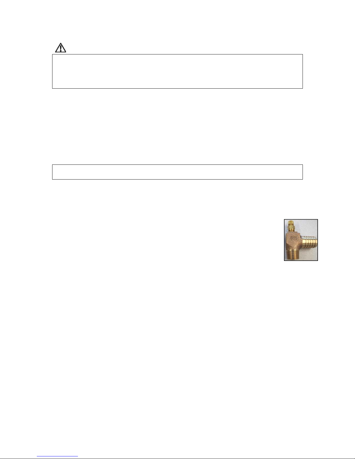
Pressure/Temperature (P/T) plugs – Should be installed in the adaptor elbow on the entering
and leaving water line of the heat pump on a closed system. (Figure 3) A thermometer can be
inserted into the P/T ports to check entering and leaving water temperatures. A pressure gauge
can also be inserted into these P/T ports to determine the pressure differential between the
entering and leaving water. This pressure differential can then be compared to the engineering
specifications data to determine the flow rate of the system. Non Pressurized Loops require an
air separator/stand pipe to eliminate air and to hold enough fluid to compensate for the expansion and
contraction of the loop pipe and fluid. Purge and fill valves should be placed between the loop manifold valves
and the insulated pump pack.
A Flow Meter is an important part of the system. It provides a visual indicator of loop flow in GPM.
A flow meter can be installed on either side of the pump pack, but must be installed per manufacture
recommendations so it reads accurately.
Non Pressurized Loops require an air separator/stand pipe to eliminate air and to hold enough fluid to
compensate for the expansion and contraction of the loop pipe and fluid. Purge and fill valves should be placed
between the loop manifold valves and the insulated pump pack. See figure 4.
P/T Adapter
Figure 3
12/06/2012 12 GI202

Pressurized Loops do not require an air separator. They require purge and fill ports between the loop manifold
valves and the insulated pump pack. After purging a pressurized loop, it should maintain 45 to 60 psi static
pressure. The Geothermal Loop Pipe stretches under pressure so may need to be pressurized above the desired
pressure several times to achieve the recommended static pressure. Pressurized loops must maintain enough
static pressure to compensate for the expansion and contraction of the loop pipe and fluid.
Loop Pump Selection – Select a loop circulation pump based upon the GPM required and total system pressure
drop. See specification, page 4. Geothermal heat pump Btu/h capacity and efficiency are directly related to the
GPM flow through the unit.
Vibration pad – We recommend setting the unit on a sound vibration pad, available from most distributors or
accessories price sheet – E2-0122.
Water quality – Models with standard copper heat exchanger coils require the installer to evaluate water quality
and meet minimum water properties.
pH < 7.5
Calcium hardness < 100 PPM
Iron fouling < 0.2 PPM (Ferrous)
< 0.5 PPM of oxygen
Hydrogen sulfide (H
S) < 0.5 PPM
2
Chloride levels < 20 PPM
Erosion/clogging < 10 PPM, particles
Filter, if required < 800 micron size
Softened water is recommended along with 2 oz of common house chlorine bleach for every 10 gallons of
water.
12/06/2012 13 GI202
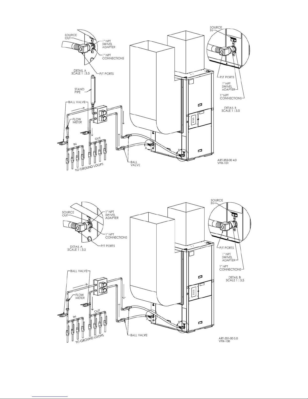
Figure 4 – Non-Pressurized Closed Loop with Flow Center – Typical piping diagram.
Figure 5 – Pressurized Closed Loop with Flow Center – Typical piping arrangement.
12/06/2012 14 GI202
Antifreeze
When considering the earth loop solution, water quality is very important. TTHERM GEO recommends a
minimum of soft water (not well water) treated with 2 oz. of household chlorine bleach for each 10 gallons of
total volume. TTHERM GEO’s recommended antifreeze concentration is 22% which will yield a freeze
protection of 18° F. This concentration of glycol requires additional additives to protect the system. TTHERM
GEO recommends Enviro-Guard HD propylene glycol for this reason.
Over antifreeze protecting a loop field decreases pumping capacity when the loop gets cold and reduces thermal
transfer. Under protecting a loop field will cause the THERM GEO heat pump to take action protecting itself
from damage. This action will result in a loss of geothermal capacity, and AUX heat may be required to
maintain the temperature in the home.
Table 2 – Approximate Fluid Volume (gal) per 100ft
Pipe Size Volume Pipe Size Volume
Polyethylene
¾” IPS SDR 11 3.02 1” 4.1
1” IPS SDR 11 4.73
1-1/4” IPS SDR 11 7.55 1” 4.5
1-1/2” IPS SDR 11 9.93 1.25” 6.8
2” IPS SDR 11 15.36
Rubber Hose
Copper
Type M
1.25” 6.4
1.5” 9.5
WARNING
PREVENTING FREEZE-UP IS INSTALLER/USER RESPONSIBILITY. DAMAGE CAUSED BY
FREEZE-UP IS NOT COVERED BY WARRANTY.
CAUTION
Softened water is recommended along with 2 oz of common household chlorine bleach for every
10 gallons of water.
WARNING
NOT ALL GLYCOLS PROVIDE THE SAME LEVEL OF CONCENTRATION. MOST GLYCOLS
DO NOT CONTAIN ENOUGH INHIBITORS FOR THE RECOMMENDED CONCENTRATION
LEVELS.FOR GEOTHERMAL SYSTEMS..
Open Loop– An open system gets its name from the open discharge of water after it has been used by the heat
pump. A well pump and well must be available that can supply all of the water requirements of the heat pump
along with any other water requirements drawing off that same well. The well must be capable of supplying the
heat pumps required flow rated for up to 24 hours per day for the coldest winter day.
Figure 6 shows the necessary components for water piping of an open system. First a bladder type pressure tank
with a “draw down” of at least 1-1/2 to 2 times the well pump capacity must be installed on the supply side of
the heat pump to prevent short cycling the well pump. Constant pressure well pumps need to deliver the GPM
flow rate of the TTHERM GEO heat pump and other possible consecutive demands. Shut off valves and boiler
drains on the entering and leaving water lines are necessary for future maintenance. A screen strainer is placed
on the supply line with a mesh size of 40 to 60 and enough surface area to allow for particle buildup between
cleanings. Hose kits are installed between the heat pump and ridged plumbing to reduce vibration transfer. Hose
kits have pressure temperature (P/T) plugs placed in the supply and discharge hydrant elbows so that
12/06/2012 15 GI202
 Loading...