

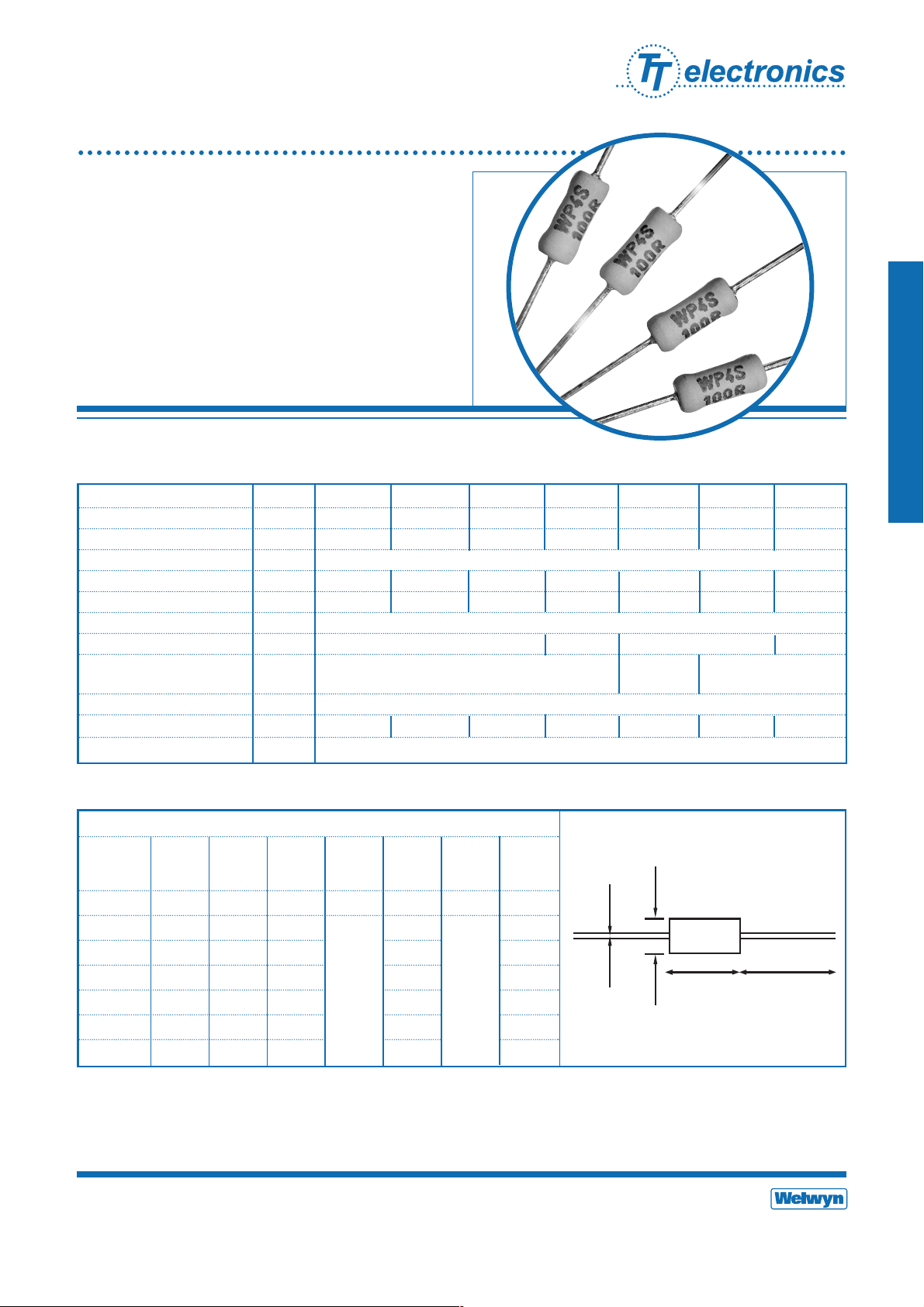
Compact Flameproof Power
Wirewound Resistors
WP-S Series
• Small size for power rating
• Enhanced pulse handling capability
• Flameproof protection
• SMD Z-form available
• RoHS compliant with Pb-free terminations
General Note
Welwyn Components reserves the right to make changes in product specification without notice or liability.
All information is subject to Welwyn’s own data and is considered accurate at time of going to print.
© Welwyn Components Limited · Bedlington, Northumberland NE22 7AA, UK
Telephone: +44 (0) 1670 822181 · Facsimile: +44 (0) 1670 829465 · Email: info@welwyn-tt.com · Website: www.welwyn-tt.com
Issue D · 04.06
A subsidiary of
TT electronics plc
Welwyn Components
Dimensions (mm) & Weight (g)
Type L max D max f min d nom PCB Min Wt.
mount bend nom
centres radius
WP1S 6.2 2.8 21.20 0.6 10.20 0.6 0.22
WP2S 9.0 3.6 19.80 12.70 0.50
WP25S 12.5 4.5 17.80 18.40 0.50
WP3S 14.5 5.2 24.55 20.30 1.10
WP4S 13 5.6 22.75 18.90 1.00
WP5S 16.5 7.0 23.55 22.86 1.75
WP7S 25.0 8.8 28.30 31.40 4.40
A high purity ceramic substrate is assembled with interference fit end caps to which are welded the terminations. The resistive
element is wound on the substrate and welded to the caps. Flameproof silicone cement coating is applied prior to marking with
indelible ink. The components are then leadformed if required and packed.
Electrical Data
Physical Data
Construction
WP1S WP2S WP25S WP3S WP4S WP5S WP7S
Power rating at 25°C watts 1 2 2.5 3 4 5 7
5s overload rating at 25ºC watts 5 10 12.5 15 20 25 35
Short pulse performance See Pulse Performance graphs
Resistance range ohms R068 to 430R R05 to 900R R05 to 900R R01 to 2K2 R01 to 10K R015 to 6K8 R15 to 10K
Limiting element voltage volts 50 50 75 100 100 150 150
TCR ppm/°C <1R: 350 ≥1R: 200
Isolation Voltage volts 250 350 500 700
Resistance Tolerance %
Standard Values E24 preferred
Thermal Impedance °C/watt 140 110 90 82 62 54 35
Ambient temperature range °C -55 to +155
<20R: 5 ≥20R: 1, 2, 5
<20R: 5 ≥20R: 1, 2, 5
<R10: 5
≥R10: 1, 2, 5
0.8
1.2
D
d
Lf
Compact Flameproof Power
Wirewound Resistors
WP-S Series
Welwyn Components
Performance Data
Maximum Typical Change
Load at rated power: 1000hrs @ 25°C ∆R% 5 +0.001Ω 3
Dry heat: 1000hrs @ 200°C ∆R% 5 +0.001Ω 3
Short term overload (5 x Pr for 5s) ∆R% 5 +0.001Ω 1
Derating from rated power @25°C Zero at 280°C
Climatic ∆R% 5 +0.001Ω 2
Climatic category 55/200/56
TRC & Vibration ∆R% 5 +0.001Ω 1
Robustness & solder heat ∆R% 5 +0.001Ω 1
Long term damp heat (56 days) ∆R% 5 +0.001Ω 1
Material: Hot tin dipped copper wire
Strength: The terminations meet the requirements of IEC 68.2.21
Solderability: The terminations meet the requirements of IEC 115-1 Clause 4.17.3.2
Terminations
WP1S, WP2S, WP25S and WP3S resistors R10 and above are marked with four colour bands in conformance with IEC62. Values
below R10 are marked with three bands (two digits indicating value in milliohms, and tolerance); there is no multiplier band.
WP4S, WP5S and WP7S resistors are legend marked with type reference, resistance value and tolerance.
Marking
The body protection and marking are resistant to all normal industrial cleaning solvents suitable for printed circuits.
Solvent Resistance
The resistor coating will not burn or emit incandescent particles under any condition of applied temperature or power overload.
Flammability
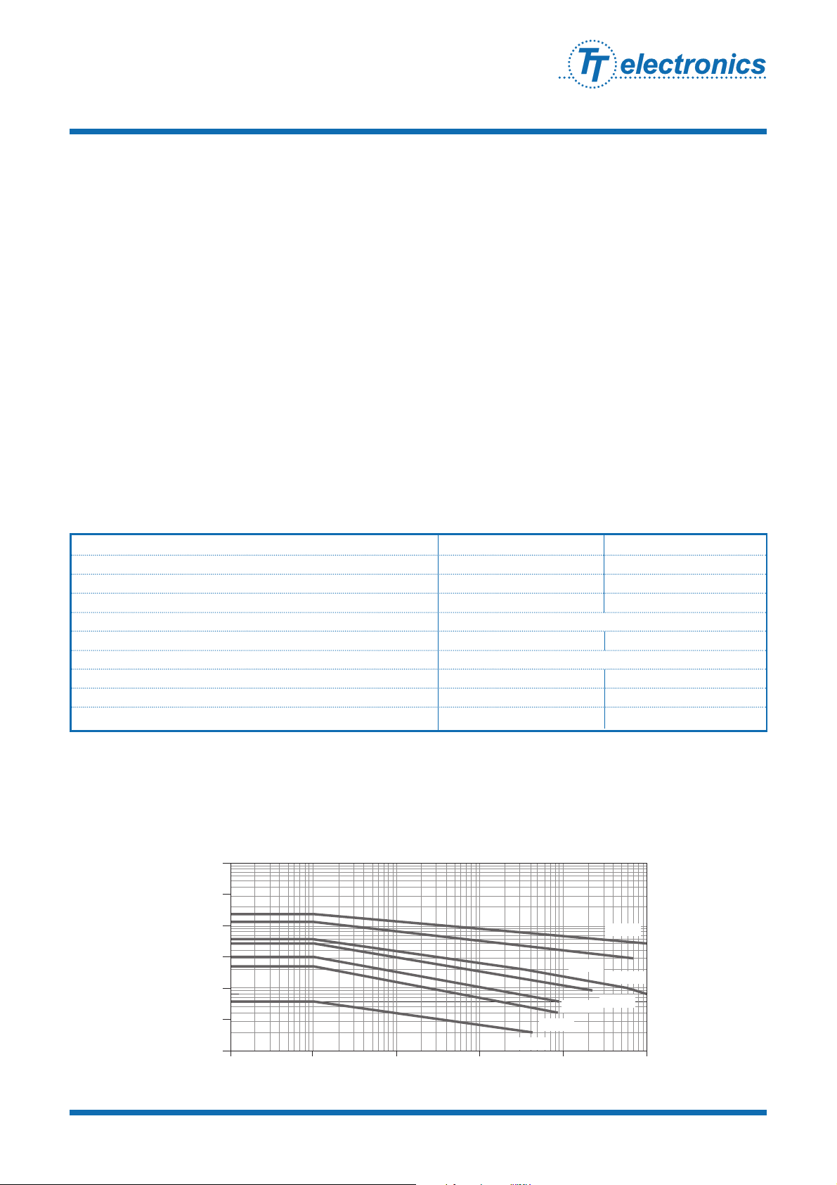
The pulse energy capacity limits in the graph below relate to pulses below 100ms duration, low mean power dissipation and at
25ºC.
Pulse Performance
© Welwyn Components Limited Bedlington, Northumberland NE22 7AA, UK
Telephone: +44 (0) 1670 822181 · Facsimile: +44 (0) 1670 829465 · Email: info@welwyn-tt.com · Website: www.welwyn-tt.com
Issue D · 04.06
WP-S Short Pulse Energy Capacity
100
10
1
Energy (joules)
0.1
WP2S
WP1S
0.1 1 10 100 1000
Value (ohms)
WP5S
WP25S
WP7S
WP4S
WP3S
10000

1. If the resistors are to dissipate full rated power, it is recommended that the terminations should not be soldered closer than
4mm from the body.
2. Due to operating temperature limits imposed by some PCB materials, derating may be necessary. An estimate of the
temperature rise to be expected at the center of the body can be calculated using the thermal impedance figures given under
Electrical Data.
3. WP-S resistors can also be supplied with radial, goalpost or lancet pre-formed leads. WP2S, WP3S, WP4S and WP5S are also
available in an SMD format with Z formed leads and packed in blister tape. Consult factory for details.
Application Notes
Radial Goalpost Lancet Z-form
Compact Flameproof Power
Wirewound Resistors
WP-S Series
Welwyn Components
© Welwyn Components Limited Bedlington, Northumberland NE22 7AA, UK
Telephone: +44 (0) 1670 822181 · Facsimile: +44 (0) 1670 829465 · Email: info@welwyn-tt.com · Website: www.welwyn-tt.com
Issue D · 04.06
The standard packaging for WP-S is taped. The critical dimensions are shown in Figure 1. The component wires will not
protrude beyond the outside edge of the tapes. Taped product is then packed into boxes or onto reels; see Ordering Procedure
for details. Alternative packaging is available by request. Pre-formed resistors are supplied loose packed in plastic bags or boxes.
Packaging
Dimensions (mm) b c
WP1S 52 5
WP2S 52 5
WP25S 52 5
WP3S 67 10
WP4S 63 10
WP5S 63 10
WP7S 85 10
Figure 1
C
f1 f2
66
Body location f1 - f2 1.4mm
b
<

Compact Flameproof Power
Wirewound Resistors
WP-S Series
Welwyn Components
Example: WP2S at 680 ohms and 5% tolerance in ammo pack box of 2500 pieces -
Ordering Procedure
© Welwyn Components Limited Bedlington, Northumberland NE22 7AA, UK
Telephone: +44 (0) 1670 822181 · Facsimile: +44 (0) 1670 829465 · Email: info@welwyn-tt.com · Website: www.welwyn-tt.com
Issue D · 04.06
Type WP2S – 680R J A25
Value (use IEC 62 code)
Tolerance (use IEC 62 code)
Packing
F1%
G2%
J5%
A5 WP1S 5000/box
A25 WP2S 2500/box
A15 Ammo WP25S 1500/box
A1 WP3S 1000/box Standard
A2 WP4S 2000/box
T07 Tape WP5S 750/reel
WP7S 700/reel
 Loading...