

General Note
IRC reserves the right to make changes in product specification without notice or liability.
All information is subject to IRC’s own data and is considered accurate at time of going to print.
A subsidiary of
TT electronics plc
• 4222 South Staples Street • Corpus Christi Texas 78411 USA
Wire and Film Technologies Division
Telephone: 361 992 7900 • Facsimile: 361 992 3377 • Website: www.irctt.com
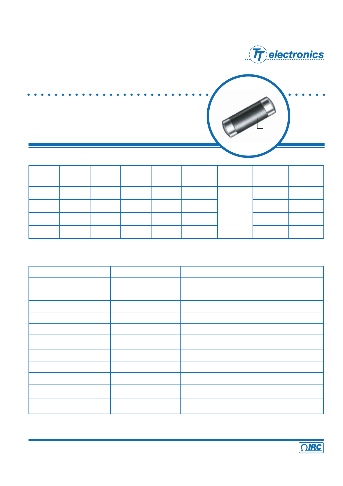
Metal Glaze™ thick
film element fired
at 1000°C to solid
ceramic substrate
High
temperature
dielectric
coating
Solder over nickel
barrier
Metal Glaze™ Surface Mount
Precision Power Chip
PPC Series
• Surge tolerant
• Up to 1000 volts
• Tight TCR - 25 ppm/°C
• Tolerance down to ±0.1%
Electrical Data
Size
Code
Industry
Footprint
IRC
Type
Power
Rating at
70°C (W)
Working
Voltage
Resistance
Range
(ohms)
Tolerance
(±%)
Qty /
Reel (7")
Qty /
Reel (13")
B
1206 PPC1/8 1/8 W 200 100 - 10K
0.1% (B)
0.25% (C)
0.5% (D)
2500 10000
D
2010 PPC1/2 1/2 W 300 100 - 10K 1500 5000
F
2512 PPC1 1 W 350 100 - 10K N/A 5000
H
3610 PPC2 2W 1.33W 500 100 - 10K N/A 1500
Environmental Data
Characteristics Maximum Change Test Method
Temperature Coefficient
As specified MIL-R-55342E Par 4.7.9 (-55°C + 125°C)
Thermal Shock
±0.5% + 0.01 ohm MIL-R-55342E Par 4.7.3 (-65°C + 150°C, 5 cycles)
Low Temperature Operation
±0.25% + 0.01 ohm MIL-R-55342E Par 4.7.4 (-65°C @ working voltage)
Short Time Overload
±0.5% + 0.01 ohm MIL-R-55342E Par 4.7.5 2.5 x for 5 seconds
High Temperature Exposure
±0.5% + 0.01 ohm MIL-R-55342E Par 4.7.6 (+150°C for 100 hours)
Resistance to Bonding
±0.25% + 0.01 ohm
MIL-R-55342E Par 4.7.7 (Reflow soldered to board at 260°C
for 10 seconds)
Exposure
95% minimum coverage MIL-STD-202, Method 208 (245°C for 5 seconds)
Solderability
±0.5% + 0.01 ohm MIL-R-55342E Par 4.7.8 (10 cycles, total 240 hours)
Moisture Resistance
±0.5% + 0.01 ohm MIL-R-55342E Par 4.7.10 (2000 hours at 70°C intermittent)
Life Test
±1% + 0.01 ohm
1200 gram push from underside of mounted chip for 60
seconds
Terminal Adhesion Strength
±1% + 0.01 ohm
no mechanical damage
Chip mounted in center of 90mm long board, deflected 1mm
so as to exert pull on chip contacts for 5 seconds
√
PPC Series Issue November 2008 Sheet 1 of 3
• 4222 South Staples Street • Corpus Christi Texas 78411 USA
Wire and Film Technologies Division
Telephone: 361 992 7900 • Facsimile: 361 992 3377 • Website: www.irctt.com
Metal Glaze™ Surface Mount
Precision Power Chip
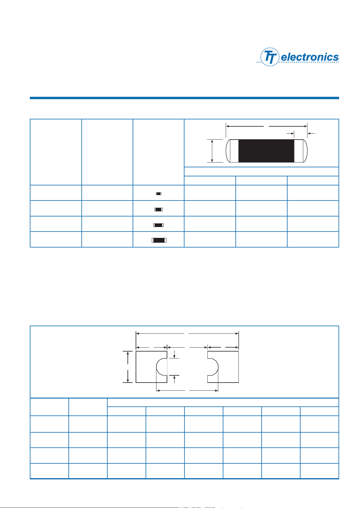
Physical Data
Size Code
Industry
Footprint Actual Size
Dimensions (Inches and (mm))
L W C
B 1206
0.128 ± 0.007
(3.25 ± 0.18)
0.057 ± 0.006
(1.45 ± 0.15)
0.020 ± 0.010
(0.51 ± 0.25)
D 2010
0.200 ± 0.010
(5.08 ± 0.25)
0.079 ± 0.006
(2.01 ± 0.15)
0.030 ± 0.010
(0.761 ± 0.25)
F 2512
0.251 ± 0.010
(6.38 ± 0.25)
0.079 ± 0.006
(2.01 ± 0.15)
0.040 ± 0.010
(1.02 ± 0.25)
H 3610
0.367 ± 0.010
(9.32 ± 0.25)
0.105 ± 0.006
(2.67 ± 0.15)
0.050 ± 0.010
(1.27 ± 0.25)
Recommended Solder Pad Dimensions (Reflow):
Size
Code
Industry
Footprint
Dimensions (Inches and mm))
A B C D E F
B 1206
0.076
(1.93)
0.093
(2.36)
0.058
(1.47)
0.098
(2.49)
0.032
(0.81)
0.211
(5.36)
D 2010
0.111
(2.82)
0.126
(3.20)
0.096
(2.44)
0.152
(3.86)
0.040
(1.02)
0.318
(8.08)
F 2512
0.121
(3.07)
0.126
(3.20)
0.127
(3.23)
0.183
(4.65)
0.040
(1.02)
0.369
(9.37)
H 3610
0.170
(4.32)
0.160
(4.06)
0.213
(5.41)
0.273
(6.93)
0.044
(1.12)
0.553
(14.05)
F
E
B
D
A
C
A
L
C
W
Recommended Solder Pad Dimensions (Reflow):
To ensure excellent solderability performance, IRC recommends the following pad design. This design will provide
a large repeatable solder fillet to the PPC resistor on reflow processes and will provide maximum heat transfert
to the PC board in high power applications. By placing the PPC on the solder paste while the paste is in the
"tacky" state, the PPC will be held in position until solder reflow begins. The pad design thes uses the surface
tension of the molten solder to pull the component to the center of the solder pad. The placement of a via rising
above the board level directly beneath the PPC is not recommended.
PPC Series Issue November 2008 Sheet 2 of 3
• 4222 South Staples Street • Corpus Christi Texas 78411 USA
Wire and Film Technologies Division
Telephone: 361 992 7900 • Facsimile: 361 992 3377 • Website: www.irctt.com
Sample Part No.
IRC Type
PPC 1/8, 1/2, 1, 2
Resistance Value (EIA 4-digit code)
(≥100Ω - First 3 significant digits plus 4th digit multiplier)
Example: 100
Ω = 1000; 1000Ω = 1001
(>100Ω - "R" is used to designate decimal)
Example: 10
Ω = 10R0; 0.25Ω = R250
Tolerance (EIA format)
B = ±0.1%, C = ±0.25%, D = ±0.5%
RoHS Indicator
LF indicates RoHS compliance
Blank designates 60% Sn / 40% Pb Solder
Packaging
(BLK = Bulk, 7 = 7" Reel, 13 = 13" Reel)
Ordering Data
PPC1 25 1001 F LF 13
Metal Glaze™ Surface Mount
Precision Power Chip
Size
Code
Industry
Footprint
Reel
Diameter*
Quantity Per Reel Carrier Tape Width Component Pitch
B 1206
7", 13" 2,500 max., 10,000 max. 8mm 4mm
D 2010
7", 13" 1,500 max., 5,000 max. 12mm 4mm
F 2512
13" 5,000 max. 12mm 4mm
H 3610
7" 1,500 max. 24mm 4mm
Standard Reel Packaging Per EIA-481
* The 13" reel is considered standard and will be supplied unless otherwise specified.
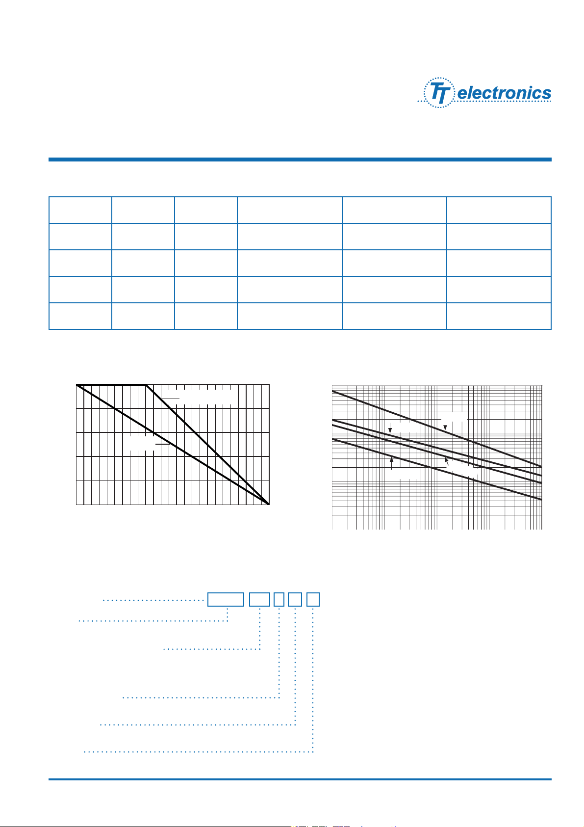
30 40 50 60 70 80 90 100 110 120 130 140 150
% of Rated Power
100
80
60
40
20
0
Ambient Temperature (°C)
PPC 1/8, 1/2, 1
PPC 2
Power Derating Curve
Specify type, resistance, tolerance, RoHS-Compliance and packaging.
This example is for a Surface Mount Precision Power Chip.
Repetitive Surge Curve
0.0001 0.0010 0.0100 0.1000 1.0000
.1msec 1msec 10msec 100msec 10000msec
Peak Power (watts)
Surge or Pulse Duration (seconds)
PPC 1
PPC 2
PPC 1/8
1000
100
10
1
PPC 1/2
PPC Series Issue November 2008 Sheet 3 of 3

This datasheet has been downloaded from:
www.EEworld.com.cn
Free Download
Daily Updated Database
100% Free Datasheet Search Site
100% Free IC Replacement Search Site
Convenient Electronic Dictionary
Fast Search System
www.EEworld.com.cn
All Datasheets Cannot Be Modified Without Permission
Copyright © Each Manufacturing Company
 Loading...