

TRANSMISSION
SERVICE
TECHNOLOGY
TT100
USER’S GUIDE
SAFETY SUMMARY
WARNING – MOTION HAZARDS
Engine parts that are in motion can cause serious injury or death. When working near moving engine parts,
wear snug fit clothing and keep hands, fingers and hair away from moving parts. Keep hoses and tools
clear of moving parts. Hoses and tools can be thrown through the air if not kept clear of moving engine
parts. Never wear loose fitting clothing or allow long hair to be exposed to the engine compartment.
The unexpected movement of a vehicle can cause serious injury or death. When working on a vehicle,
always set the parking brake or block the wheels of the vehicle being serviced.
WARNING
Read these instructions completely before using the T- T ECH and save them for future reference.
Before using the T- T ECH, read these instructions and the instruction manual/safety information
provided by the car, truck, boat or equipment manufacturer. Following all manufacturers’
instructions and safety procedures will reduce the risk of accident.
All lead-acid batteries (car, truck and boat) produce hydrogen gas which may violently explode in
the presence of fire or sparks. Do not smoke, use matches or a cigarette lighter while near
batteries. Do not handle the battery while wearing vinyl clothing because static electricity sparks
are generated when vinyl clothing is rubbed. Review all cautionary material on the T- T ECH and in
the engine compartment.
Always wear eye protection, appropriate protective clothing and other safety equipment when
working near lead-acid batteries. Do not touch eyes while working on or around lead-acid batteries.
Use extreme care while working within the engine compartment, because moving parts may cause
severe injury. Read and follow all safety instructions published in the vehicle's Owner's Manual.
Congratulations on the purchase of your new T-TECH Transmission Fluid Exchange System. The following safety
information is provided as a guideline to help you operate your new transmission fluid exchange system under the
safest possible conditions. Any equipment can be potentially dangerous to use when safety or safe handling
instructions are not known or not followed.
A procedure step preceded by
to a person if proper safety precautions are not heeded. A procedure step preceded by CAUTION is an indication
that the step contains a procedure that might damage the equipment being used.
WARNING is an indication that the step contains a procedure that might be injurious
Safety Instructions
Tools are dangerous if misused or abused. To reduce risk of discomfort, illness, injury or even death, read,
understand, and follow these following safety instructions. In addition, make certain that anyone else that uses this
equipment understands and follows these safety instructions as well.
Retain these instructions for future reference. Read all safety instructions carefully before attempting to install,
operate or service this equipment. Failure to comply with these instructions could result in personal injury and/or
property damage. Published standards on safety are also available. For additional information concerning safety,
refer to the following standards and comply with them, as applicable.
ANSI Standard Z87.1 — SAFE PRACTICE FOR OCCUPATION AND EDUCATIONAL EYE AND FACE PROTECTION
— obtainable from the American National Standards Institute, 1430 Broadway, New York, NY 10018
The following safety alert symbols identify important safety messages in this manual. When you see one of the
symbols shown here, be alert to the possibility of personal injury and carefully read the message that follows.
2
WARNING – HEAT HAZARDS
Vehicle transmissions can be very hot and the fluid is under pressure when the vehicle is running.
Opening a hot, pressurized transmission line can cause hot transmission fluid to be forcibly sprayed
in all directions. Wait until the engine has cooled in the vehicle being serviced before removing a
system line or in any way opening the vehicle transmission system when the system is hot and under
pressure.
Many component parts, in a vehicle that has been running, are hot and can cause serious skin burns.
Take care to not touch hot components. Wait until the vehicle has cooled before attempting to
service.
WARNING – POISONOUS FLUID HAZARDS
This fluid exchanger is intended for transmission fluid only. Transmission fluid is poisonous if
ingested. Ingesting transmission fluid can cause serious illness. Keep transmission fluid where children
and pets cannot get to it. If some transmission fluid should be accidentally swallowed, take the person
or pet in for medical assistance immediately. Be sure to identify to the doctor specifically what it was
that was ingested. If medical assistance is not immediately available, call the local poison center.
Avoid contact with skin and eyes. If skin contact is made, flush affected area with water and wash
immediately. For eye contact, flush with water and apply a suitable eye wash. If irritation persists,
contact a physician.
WARNING – FUME HAZARDS
FUMES, GASSES, AND VAPORS CAN CAUSE DISCOMFORT, ILLNESS, AND DEATH!
Breathing vehicle exhaust emissions can cause sickness, injury, or death. Always work in a properly
ventilated area when servicing a vehicle with the engine running. Never run an engine without proper
ventilation for its exhaust.
Stop the exchange process if you develop momentary eye, nose, or throat irritation. Eye, nose, or
throat irritation indicates inadequate ventilation. Stop work and take necessary steps to improve
ventilation in the work area.
A BATTERY EXPLOSION CAN INJURE, AND CAUSE PROPERTY DAMAGE! A spark near a battery
can cause an explosion. To reduce the risk of a spark near a battery, make the positive connection to
the battery first then the negative connection to the vehicle chassis, at a point away from the battery.
WARNING – EXPLOSION HAZARDS
Do not tip or rock the
T- T ECH
. Such actions could result in serious injury or property damage. Always
lock the wheels when stationary to avoid unintentional movement of the
T- T ECH
.
WARNING – T I P OVER HAZARDS
!
Hot transmission fluid, under pressure, can injure the eyes. Always wear eye protection (safety
glasses) when opening transmission lines to protect the eyes against hot fluids being forcefully
sprayed into them. Ordinary glasses do not have impact resistant lenses, they are NOT safety glasses.
Always clean up transmission fluid spills immediately. Transmission fluid is very slippery when spilled.
WARNING – FLUIDS UNDER PRESSURE
WARNING: This product contains chemicals, including lead, known to the State of California to cause cancer,
birth defects and other reproductive harm. Wash hands after handling.
3

TABLE OF CONTENTS
SAFETY SUMMARY
Safety Instructions . . . . . . . . . . . . . . . . . . . . . . . . . . . . . . . . . . . . . . . . . . . . . . . . . . . . . . . . .2
Additional Safety Information . . . . . . . . . . . . . . . . . . . . . . . . . . . . . . . . . . . . . . . . . . . . . . . . . . . . . . . . . . . . . . . . . .2
Fluids Under Pressure . . . . . . . . . . . . . . . . . . . . . . . . . . . . . . . . . . . . . . . . . . . . . . . . . . . . . . . . . . . . . . . . . . . . . . . .2
Motion Hazards . . . . . . . . . . . . . . . . . . . . . . . . . . . . . . . . . . . . . . . . . . . . . . . . . . . . . . . . . . . . . . . . . . . . . . . . . . . . .2
Shock Hazards . . . . . . . . . . . . . . . . . . . . . . . . . . . . . . . . . . . . . . . . . . . . . . . . . . . . . . . . . . . . . . . . . . . . . . . . . . . . .3
Heat Hazards . . . . . . . . . . . . . . . . . . . . . . . . . . . . . . . . . . . . . . . . . . . . . . . . . . . . . . . . . . . . . . . . . . . . . . . . . . . . . . .3
Poisonous Fluid Hazards . . . . . . . . . . . . . . . . . . . . . . . . . . . . . . . . . . . . . . . . . . . . . . . . . . . . . . . . . . . . . . . . . . . . . .3
Fume Hazards . . . . . . . . . . . . . . . . . . . . . . . . . . . . . . . . . . . . . . . . . . . . . . . . . . . . . . . . . . . . . . . . . . . . . . . . . . . . . .3
Explosion Hazards . . . . . . . . . . . . . . . . . . . . . . . . . . . . . . . . . . . . . . . . . . . . . . . . . . . . . . . . . . . . . . . . . . . . . . . . . . .3
Tip Over Hazards . . . . . . . . . . . . . . . . . . . . . . . . . . . . . . . . . . . . . . . . . . . . . . . . . . . . . . . . . . . . . . . . . . . . . . . . . . . .3
INTRODUCTION
About This MANUAL . . . . . . . . . . . . . . . . . . . . . . . . . . . . . . . . . . . . . . . . . . . . . . . . . . . . . . . .6
The T-TECH Process . . . . . . . . . . . . . . . . . . . . . . . . . . . . . . . . . . . . . . . . . . . . . . . . . . . . . . . .6
T-Tech Specifications . . . . . . . . . . . . . . . . . . . . . . . . . . . . . . . . . . . . . . . . . . . . . . . . . . . . . . . . . . . . . . . . . . . . . . . .6
PREPARATION FOR USE
Fitting Organization . . . . . . . . . . . . . . . . . . . . . . . . . . . . . . . . . . . . . . . . . . . . . . . . . . . . . . . . .7
Standard Fittings Assortment Descriptions . . . . . . . . . . . . . . . . . . . . . . . . . . . . . . . . . . . . . . . . . . . . . . . . . . . . . . .7
Cabinet Drawer Storage Layouts . . . . . . . . . . . . . . . . . . . . . . . . . . . . . . . . . . . . . . . . . . . . . . . . . . . . . . . . . . . . . . .9
Special Fittings Kits . . . . . . . . . . . . . . . . . . . . . . . . . . . . . . . . . . . . . . . . . . . . . . . . . . . . . . . . . . . . . . . . . . . . . . . . .10
Removing Air From Cylinder . . . . . . . . . . . . . . . . . . . . . . . . . . . . . . . . . . . . . . . . . . . . . . . . .12
OPERATION INSTRUCTIONS
Overview . . . . . . . . . . . . . . . . . . . . . . . . . . . . . . . . . . . . . . . . . . . . . . . . . . . . . . . . . . . . . . . .13
Fill Cylinder Function . . . . . . . . . . . . . . . . . . . . . . . . . . . . . . . . . . . . . . . . . . . . . . . . . . . . . . .14
Using a Bulk Dispenser Gun . . . . . . . . . . . . . . . . . . . . . . . . . . . . . . . . . . . . . . . . . . . . . . . . . . . . . . . . . . . . . . . . . .14
Connecting to the Vehicle . . . . . . . . . . . . . . . . . . . . . . . . . . . . . . . . . . . . . . . . . . . . . . . . . . .15
Identifying Cooling Lines . . . . . . . . . . . . . . . . . . . . . . . . . . . . . . . . . . . . . . . . . . . . . . . . . . . . . . . . . . . . . . . . . . . . .15
Making Vehicle Service Connections . . . . . . . . . . . . . . . . . . . . . . . . . . . . . . . . . . . . . . . . . . . . . . . . . . . . . . . . . . .15
Fluid Exchange Function . . . . . . . . . . . . . . . . . . . . . . . . . . . . . . . . . . . . . . . . . . . . . . . . . . . .17
Bypass Feature . . . . . . . . . . . . . . . . . . . . . . . . . . . . . . . . . . . . . . . . . . . . . . . . . . . . . . . . . . . . . . . . . . . . . . . . . . . .18
Replace Existing New ATF with Different New ATF . . . . . . . . . . . . . . . . . . . . . . . . . . . . . . .18
MAINTENANCE
General . . . . . . . . . . . . . . . . . . . . . . . . . . . . . . . . . . . . . . . . . . . . . . . . . . . . . . . . . . . . . . . . .19
Troubleshooting . . . . . . . . . . . . . . . . . . . . . . . . . . . . . . . . . . . . . . . . . . . . . . . . . . . . . . . . . . .19

T-TECH APPLICATION NOTES
General . . . . . . . . . . . . . . . . . . . . . . . . . . . . . . . . . . . . . . . . . . . . . . . . . . . . . . . . . . . . . . . . .21
BMW . . . . . . . . . . . . . . . . . . . . . . . . . . . . . . . . . . . . . . . . . . . . . . . . . . . . . . . . . . . . . . . . . . .21
BMW General . . . . . . . . . . . . . . . . . . . . . . . . . . . . . . . . . . . . . . . . . . . . . . . . . . . . . . . . . . . . . . . . . . . . . . . . . . . . .21
BMW 500 Series . . . . . . . . . . . . . . . . . . . . . . . . . . . . . . . . . . . . . . . . . . . . . . . . . . . . . . . . . . . . . . . . . . . . . . . . . . .21
Chrysler . . . . . . . . . . . . . . . . . . . . . . . . . . . . . . . . . . . . . . . . . . . . . . . . . . . . . . . . . . . . . . . . .21
Dodge Dakota (to 1997) and some Ram . . . . . . . . . . . . . . . . . . . . . . . . . . . . . . . . . . . . . . . . . . . . . . . . . . . . . . . . .22
Dodge Ram (Pre-2004 Assorted Gasoline engines only) . . . . . . . . . . . . . . . . . . . . . . . . . . . . . . . . . . . . . . . . . . . .22
Some Dodge Durango and Dakota 1997-2004 . . . . . . . . . . . . . . . . . . . . . . . . . . . . . . . . . . . . . . . . . . . . . . . . . . .23
Jeep Grand Cherokee . . . . . . . . . . . . . . . . . . . . . . . . . . . . . . . . . . . . . . . . . . . . . . . . . . . . . . . . . . . . . . . . . . . . . . .23
Ford . . . . . . . . . . . . . . . . . . . . . . . . . . . . . . . . . . . . . . . . . . . . . . . . . . . . . . . . . . . . . . . . . . . .23
Ford Contour . . . . . . . . . . . . . . . . . . . . . . . . . . . . . . . . . . . . . . . . . . . . . . . . . . . . . . . . . . . . . . . . . . . . . . . . . . . . . .24
Ford Escort . . . . . . . . . . . . . . . . . . . . . . . . . . . . . . . . . . . . . . . . . . . . . . . . . . . . . . . . . . . . . . . . . . . . . . . . . . . . . . .24
Ford Explorer . . . . . . . . . . . . . . . . . . . . . . . . . . . . . . . . . . . . . . . . . . . . . . . . . . . . . . . . . . . . . . . . . . . . . . . . . . . . . .24
Ford F-Series Trucks . . . . . . . . . . . . . . . . . . . . . . . . . . . . . . . . . . . . . . . . . . . . . . . . . . . . . . . . . . . . . . . . . . . . . . . .25
Ford Taurus & Windstar . . . . . . . . . . . . . . . . . . . . . . . . . . . . . . . . . . . . . . . . . . . . . . . . . . . . . . . . . . . . . . . . . . . . . .26
Ford Windstar . . . . . . . . . . . . . . . . . . . . . . . . . . . . . . . . . . . . . . . . . . . . . . . . . . . . . . . . . . . . . . . . . . . . . . . . . . . . .26
Mercury Mountaineer . . . . . . . . . . . . . . . . . . . . . . . . . . . . . . . . . . . . . . . . . . . . . . . . . . . . . . . . . . . . . . . . . . . . . . .27
Mercury Mystique . . . . . . . . . . . . . . . . . . . . . . . . . . . . . . . . . . . . . . . . . . . . . . . . . . . . . . . . . . . . . . . . . . . . . . . . . .27
Mercury Sable . . . . . . . . . . . . . . . . . . . . . . . . . . . . . . . . . . . . . . . . . . . . . . . . . . . . . . . . . . . . . . . . . . . . . . . . . . . . .27
General Motors . . . . . . . . . . . . . . . . . . . . . . . . . . . . . . . . . . . . . . . . . . . . . . . . . . . . . . . . . . .27
Quick-Disconnect Equipped Vehicles . . . . . . . . . . . . . . . . . . . . . . . . . . . . . . . . . . . . . . . . . . . . . . . . . . . . . . . . . . .27
Allison Series 1000 . . . . . . . . . . . . . . . . . . . . . . . . . . . . . . . . . . . . . . . . . . . . . . . . . . . . . . . . . . . . . . . . . . . . . . . . .28
Mazda . . . . . . . . . . . . . . . . . . . . . . . . . . . . . . . . . . . . . . . . . . . . . . . . . . . . . . . . . . . . . . . . . .28
Mercedes-Benz . . . . . . . . . . . . . . . . . . . . . . . . . . . . . . . . . . . . . . . . . . . . . . . . . . . . . . . . . .29
Nissan . . . . . . . . . . . . . . . . . . . . . . . . . . . . . . . . . . . . . . . . . . . . . . . . . . . . . . . . . . . . . . . . . .29
Saab . . . . . . . . . . . . . . . . . . . . . . . . . . . . . . . . . . . . . . . . . . . . . . . . . . . . . . . . . . . . . . . . . . .29
Toyota . . . . . . . . . . . . . . . . . . . . . . . . . . . . . . . . . . . . . . . . . . . . . . . . . . . . . . . . . . . . . . . . . .30
Volkswagen Products . . . . . . . . . . . . . . . . . . . . . . . . . . . . . . . . . . . . . . . . . . . . . . . . . . . . . .30
Volvo . . . . . . . . . . . . . . . . . . . . . . . . . . . . . . . . . . . . . . . . . . . . . . . . . . . . . . . . . . . . . . . . . . .30
REPLACEMENT PARTS LIST
External Parts List . . . . . . . . . . . . . . . . . . . . . . . . . . . . . . . . . . . . . . . . . . . . . . . . . . . . . . . . .31
Internal Parts List . . . . . . . . . . . . . . . . . . . . . . . . . . . . . . . . . . . . . . . . . . . . . . . . . . . . . . . . .33
Fittings & Tools . . . . . . . . . . . . . . . . . . . . . . . . . . . . . . . . . . . . . . . . . . . . . . . . . . . . . . . . . . .35
PLUMBING DIAGRAM . . . . . . . . . . . . . . . . . . . . . . . . . . . . . . . . . . . . . . . . . . . . . . . . .36
WARRANTY . . . . . . . . . . . . . . . . . . . . . . . . . . . . . . . . . . . . . . . . . . . . . . . . . . . . . . . . . . . .37

INTRODUCTION
About This Manual
This manual includes a Safety Summary, Operating Procedures, Machine Preparation, Maintenance Instructions and
Troubleshooting Procedures for transmission fluid exchanging. Anyone intending to use this machine should
become familiar with all the information included in this manual (especially the Safety Summary) before attempting
to use the Transmission Fluid Exchanger. In order to properly perform a complete transmission fluid exchange,
follow all procedures in the order presented. Please take the time to study this manual before operating the
machine. Then keep this manual close at hand for future reference.
The T-TECH Process
Heat is the enemy of transmission fluid. Transmission fluid is a combination of light base oils with an extensive
additive package to control foaming, slip, lubrication, etc. Heat attacks the additive package and oxidizes or burns
it away, leaving you with only the base oils.
In order to slow the oxidation of the additive package, the vehicle manufacturers have designed an oil cooler,
usually in the radiator, that passes all of the transmission fluid through it.
T-TECH uses a patented process of harnessing the pump in the vehicle’s transmission to control the flow of fluid.
This process captures the fluid coming out of the transmission and automatically directs it into the bottom of the
T-TECH cylinder. The used ATF flowing into the bottom of the cylinder pushes against the separating piston and
directs new fluid out the top of the cylinder and back into the vehicle.
The patented T-TECH system makes it IMPOSSIBLE TO HARM A VEHICLE’S TRANSMISSION. The T-TECH
process operates exclusively on the transmission pump pressure, which essentially eliminates the possibility of
over-pressure, under-pressure, overfill or underfill.
T-TECH Fluid Exchange is the preferred method of automatic transmission service because it is designed to offer
the safest and most complete exchange of fluid in the transmission, torque converter, lines and cooler.
The need for a safe and thorough exchange of used ATF has increased as the life expectancy of vehicles increases,
the demands placed on these vehicles grows and the cost of repair rises. Today, nearly every vehicle has an OEMrecommended service for automatic transmissions.
The original pan drop method of service only captured 30% - 40% of the vehicle’s used ATF. Other mechanical
exchange machines force fluid into the vehicle under pressure and can damage the seals inside a transmission.
Discover why vehicle owners throughout North America specify
T-TECH Specifications
Max Pressure: 85 psi, 583 kPa
Weight (approx.): 96 lbs. (43.54 kg)
Depth: 32.5 in. (0.83 m)
Width: 21.5 in. (0.55 m)
Height: 51.5 in. (1.31 m)
Patents: 5,318,080, Re. 38,650; 6,082,416; 6,267,160; 6,330,934
Note: Do not leave your T-TECH in direct sunlight in extremely hot temperatures (>90ºF) for extended periods.
Such exposure can have detrimental effects on the case.
T-TECH when asking for ATF service
6
PREPARATION FOR USE
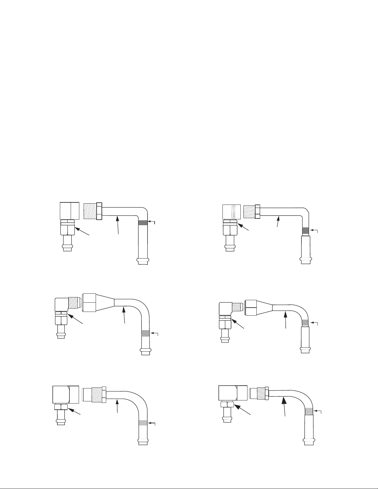
FIT301
FIT302
Red
Band
FIT304
FIT303
Red
Band
FIT306FIT305
Green
Band
FIT310
FIT309
Blue
Band
FIT312
FIT311
Blue
Band
FIT308
FIT307
Green
Band
Although minimal, T-TECH requires some preparation before use. The following instructions describe the necessary
steps to prepare your new transmission fluid exchanger for use.
Fitting Organization
Locate the standard fittings assortment and set each fitting in the T-TECH cabinet storage position identified by the
picture mounted on the backside of the cabinet cover. The standard fittings have a specific storage location inside
the T-TECH cabinet. Most of the fittings are numerically referenced and have a color-coded band for easy
identification.
Throughout each of the operating functions performed using the
T-TECH, various adapters, fittings, or attachments
will require installation in order to service a specific vehicle. This is not considered part of initial preparation for use.
In each case, the setup and connection requirements for a specific task will be added, where necessary, as part of
the procedure for that task.
Standard Fittings Assortment Descriptions
Figure 1 through Figure 14 identify the fittings/components in the standard fittings assortment.
Note: Be aware that any of these fittings along with any of the fittings in the special fittings kits can be used to
service any vehicle as needed.
Figure 1. Fitting 301 and Fitting 302
General Motors – Pre-2000 large and
heavy-duty GM cars, trucks and vans
Figure 2. Fitting 303 and Fitting 304
General Motors – Pre-2000 passenger cars,
light duty trucks and vans
Figure 3. Fitting 305 and Fitting 306
Chrysler/Jeep/Eagle – Pre-2005 Jeep Cherokee
and some passenger vehicles
Figure 5. Fitting 309 and Fitting 310
Ford – Pre-2005 large trucks and vans
Figure 4. Fitting 307 and Fitting 308
Chrysler/Dodge/Eagle – Chrysler Corp. passenger
cars [Fitting 308 also fits Volvo 720/740]
Figure 6. Fitting 311 and Fitting 312
Ford – Small passenger cars and light duty trucks
7
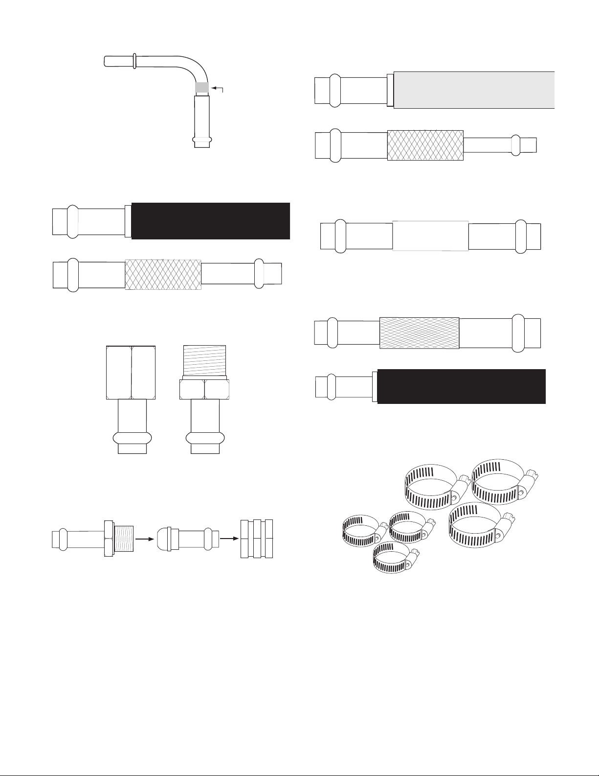
Figure 7. Fitting 314
Blue
Band
FIT315
FIT316
YELLOW
FIT320 FIT323
FIT317
FIT318
BLACK
FIT321
BLACK
FIT324
Ford/Lincoln/Mercury – Fits earlier Ford, Lincoln, and
Mercury small and large passenger vehicles
Figure 9. Fitting 317 and Fitting 318
Any vehicle with 5/16 inch hose connections
Figure 8. Fitting 315 and Fitting 316
Any vehicle with 1/4 inch hose connections
Figure 10. Fitting 319
Any vehicle with 3/8 inch hose connections
Figure 12. Fitting 321 and 324
Any vehicle with 1/2 inch hose connections
Figure 11. Fitting 320 and Fitting 323
Any vehicle with 1/4 inch pipe fittings. Sometimes
used to bypass quick connect receptacles
Mercedes Benz and some BMW
8
Figure 13. Fitting 322
Figure 14. Hose Clamps in two sizes, three each
Cabinet Drawer Storage Layouts
301
302
303
304
305
306
308
307
309
310
311
312
314
RED
RED
GRN
GRN
BLU
BLU
BLU
YELLOW
315
317
316
318
319
321
322
320
323
Hose
Clamps
324
1
2
3
4
5
TECHT
-
®
Failure to follow instructions may cause damage or explosion;
always shield eyes. Read entire instruction manual before use.
WARNING
Do not exceed 75 PSI input pressure when filling the T-TECH.
CAUTION
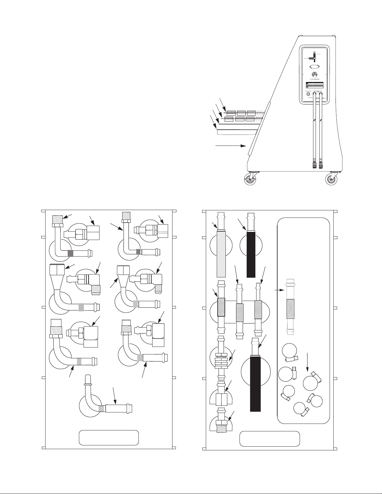
The storage trays in the T-TECH cabinet are defined in
Figure 15. Figure 16 and Figure 17 show the tray layout
for storage of the standard fittings in trays 3 and 4
respectively. The numbers shown in the illustration are
the specific fitting number for the standard fittings and
will be referred to throughout this manual.
Note: The numbers in Figures 16 and 17 correspond
to standard fittings FIT301-FIT324. (There is no fitting
numbered FIT313.)
Figure 15.
1. Special Fittings Tray
2. Special Fittings Tray
3. Standard Fittings Tray
4. Standard Fittings Tray
5. Storage for Manual
Figure 15. T-TECH cabinet organization
Figure 16. Standard Fittings Storage Tray (3) Figure 17. Standard Fittings Storage Tray (4)
9
Special Fittings Kits
T- TECH
SPECIAL FITTINGS
T- TECH
SPECIAL FITTINGS
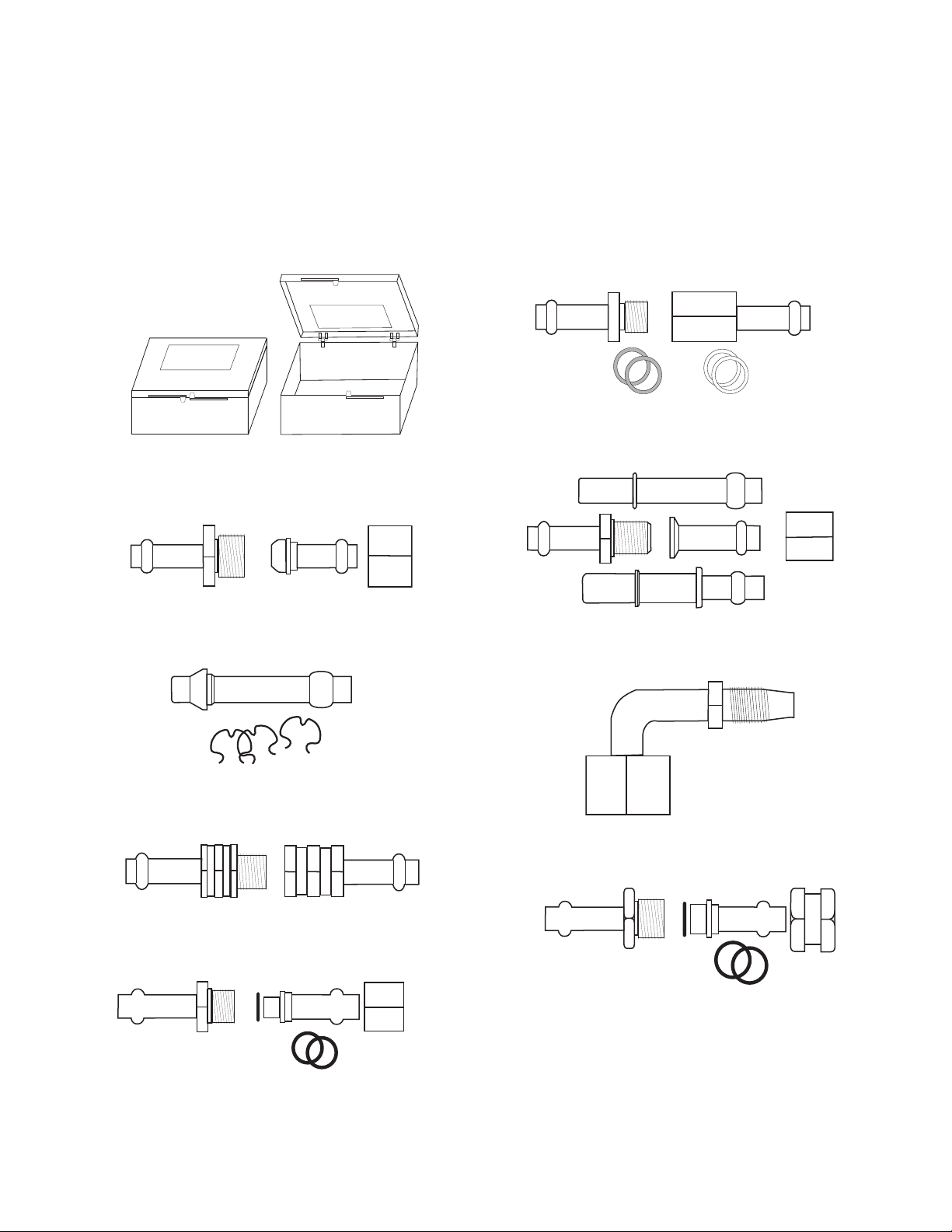
Optional accessories on TT100 must be ordered separately. The special fittings shown in Figure 18 through Figure
34 are stored in small plastic cases (Figure 18) in trays 1 and 2, inside the
CAUTION: Each of the special fittings kits displayed here is a unique matched set of fittings intended for special
use. Always keep the fittings in each kit together. When the fittings in these kits become mismatched, it is possible
to damage the fittings or the vehicle.
Figure 18. FIT165
Replacement plastic storage cases for Special Fittings Kits
T-TECH cabinet (Figure 15).
Figure 19. FIT401
Ford Escort/Nissan/Mazda
Figure 20. FIT402
BMW
Figure 22. FIT404
3/8" Quick Connect, GM/Chrysler
Figure 24. FIT406
Ford/Dodge
Figure 21. FIT403
Ford Taurus/Dodge Full Size Trucks
Figure 23. FIT405
Some Jeep/Chrysler
Figure 25. FIT407
BMW 5 Series and 3 Series
10
Figure 26. FIT408
Ford Contour/Mercury Mystique
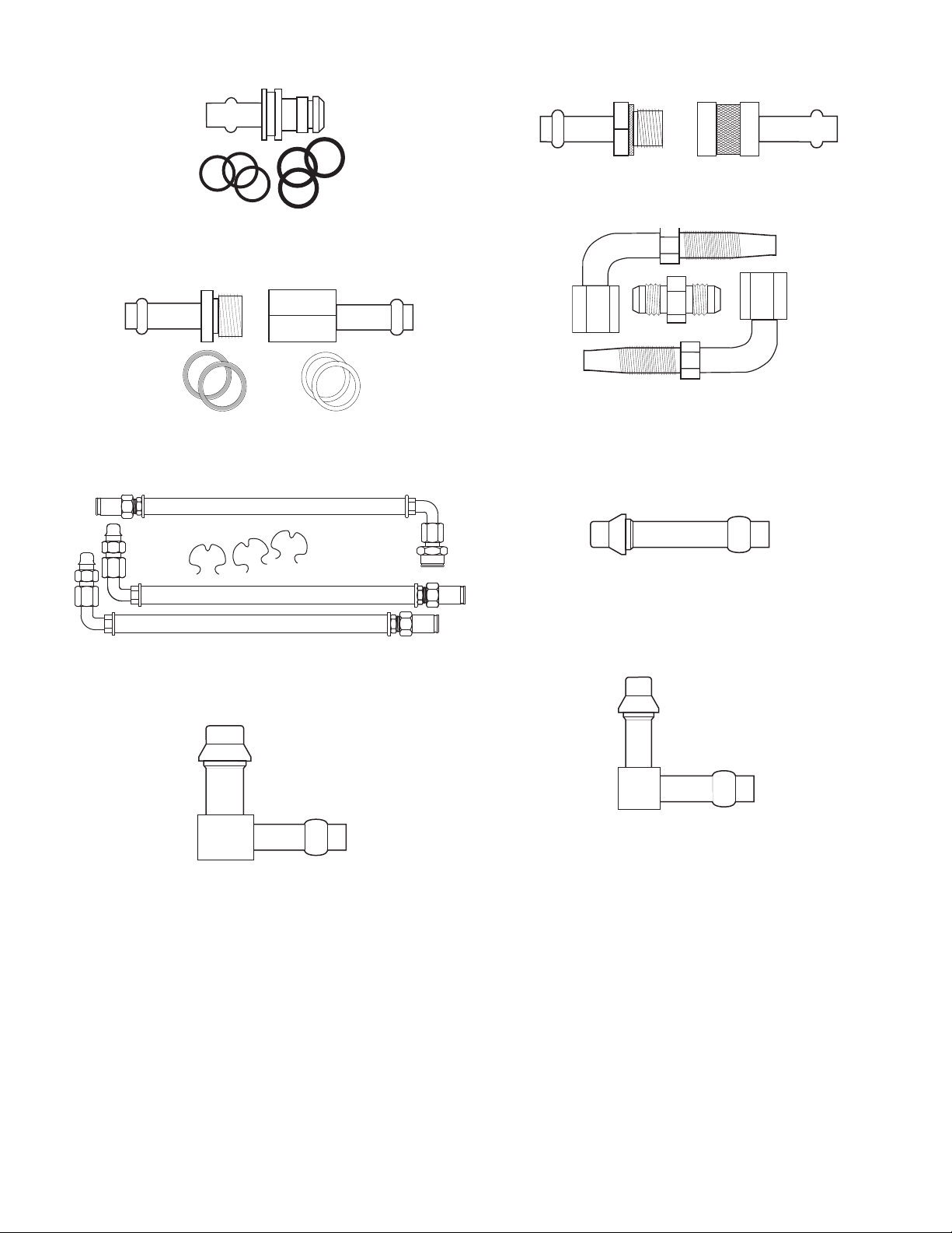
Figure 27. FIT409
Volvo
Figure 29. FIT411
Mazda/Ford Banjo Fittings
Figure 28. FIT410
Saab
Figure 30. FIT412
Pre-2005 Dodge Durango/Dakota
Figure 32. FIT414
3/8" Quick Connect, Ford
Figure 31. FIT413
Allison 1000 Series
Figure 33. FIT415
90º 1/2" Quick Connect, Ford
Figure 34. FIT416
90º 3/8" Quick Connect, GM/Chrysler
11
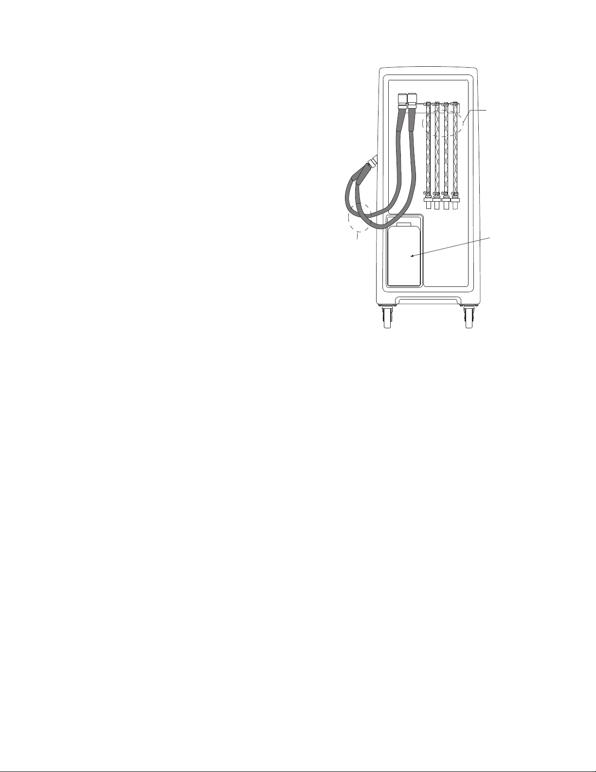
Removing Air From the Cylinder
Service
Transfer
Hoses
Overflow
Ta nk
Service
Hose
Adapters
When using the T-TECH for the first time, there may be
space at the top of the cylinder (air in the cylinder). If not
corrected, this condition may short future exchanges. If for
some reason the piston is at the bottom of the cylinder, or
there is large air pocket above the piston, the piston can be
moved to the top of the cylinder by the following method.
1. Set CONTROL VALVE to SERVICE VEHICLE.
2. Attach a service hose adapter to one of the service
transfer hoses.
3. Insert an air nozzle into the end of the service hose
adapter.
4. Control the air line at 10 psi (138 kPa) or less and
begin filling the bottom of the cylinder with air.
Figure 35. Hoses and Hose Adapters
12

OPERATION INSTRUCTIONS
CONTROL
VALVE
Service Transfer
Hose Connections
(Hard Plumbed)
Control Valve
System
Pressure Gauge
Service Port
TECHT
-
®
Failure to follow instructions may cause damage or explosion;
always shield eyes. Read entire instruction manual before use.
WARNING
Do not exceed 75 PSI input pressure when filling the T-TECH.
CAUTION
For first time use, do not perform any of the following procedures until you have completed the procedures in
Preparation For Use. All procedures must be performed in the order presented.
Figure 36. Control Valve Positions
For each service being performed, always make certain to fill the cylinder with the specific type of ATF required by
the vehicle to be serviced. Once Preparation For Use has been completed, a typical service consists of the
following procedures in the order presented.
1. Fill Cylinder Function
2. Connecting to the Vehicle
3. Fluid Exchange Function
Figure 37. TT100 Side View
13

Overflow
Tank
Bulk Fill
Service
Port
Hoses
To and From
The
Transmission
Automatic
Bypass
Line
Automatic
Alignment
Valve
Check
Valve
Three
Way
Valve
Valve
in
FILL
Position
Check
Valve
Check
Valve
Check
Valve
Old
or
Dirty
Fluid
New
Fluid
Pressure
Relief
Valve
System
Pressure
Bulk
Dispenser Gun
Nipple
Female Coupler
Connects to Male
Coupler on T-Tech
Male
Coupler
on
T-TECH
Control
Panel
Fill Cylinder Function
The Fill Cylinder function is used to fill the T-TECH cylinder with new ATF and empty the cylinder of old ATF.
CAUTION: Fill cylinder completely. Air below the piston will result in an incomplete exchange as this air will
compress and not move the piston at beginning of the exchange process. (This condition usually occurs only during
the initial fill.)
Using a Bulk Dispenser Gun
To use this method, a bulk dispenser gun (see Figure 38) accessory kit must be used. The accessory kit is an
optional kit not supplied with the T-TECH. The bulk dispenser gun accessory kit must be ordered separately (Part
No. FIT200, see Replacement Parts List).
CAUTION: Ensure that your air delivery system does not exceed
75 psi at the point of delivery. Many air systems have a 3:1 or 4:1
pressure ratio – this means you must dial your system down to
compensate for the output delivery ratio. Monitor the gauge on
the T-TECH control panel to ensure that 75 psi is not exceeded.
CAUTION: Fill cylinder completely. Air below the piston will result in
an incomplete exchange as this air will compress and not move the
piston at beginning of the exchange process. If this is the first time
T-TECH machine has been filled, there will be air under the
your
piston instead of old ATF. The air must be allowed to exit just
as if it were old fluid. See Note on Step 3 below.
Figure 38. Bulk Dispenser Gun Connection
T-TECH cylinder).
14
1. Determine ATF type needed for your next service.
2. Set CONTROL VALVE (on control panel on the side of the unit) to FILL CYLINDER.
3. Attach a service hose adapter to the end of each service transfer hose.
Note: Although the used fluid will exit only one service hose when filling the cylinder with new fluid,
it is critical that you connect service hose adapters to both service transfer hoses every time
you fill the T-TECH.
4. Insert both service hoses into a container suitable for collecting and disposing of old ATF. The container
must be capable of holding a minimum of 18 quarts (the full capacity of the
Note: Always follow your local environmental protection agency guidelines for proper disposal
of ATF.
5. Using the proper fittings that correspond to
your dispenser gun, connect the bulk dispenser
gun to the CYLINDER FILLING port on the
control panel on the side of the
T-TECH
(see Figure 38) .
6. Press the trigger on the bulk dispenser gun.
The flow direction for filling new fluid from a
bulk dispenser gun is shown in Figure 39.
7. Verify that the pressure gauge on the
control panel does not exceed a reading of
75 lbs.
8. New fluid should begin flowing into the top of
the cylinder. An equal amount of used ATF is
being displaced and forced out of the
through one of the service hoses and into your
T-TECH
T-TECH
designated used-ATF disposal container.
Figure 39. Flow Direction From A Bulk Dispenser Gun
9. Continue the process until the cylinder is filled
with the required amount of new ATF.

Connecting to the Vehicle
Cooling
Lines
Upper
Radiator
Fitting
Lower
Radiator
Fitting
Upper
Transmission
Fitting
Lower
Transmission
Fitting
Cooling
Lines
Lower
Radiator
Fitting
Upper
Transmission
Fitting
Lower
Transmission
Fitting
Secondary
Transmission
Cooler
Location #1
Transmission
Fittings
Location #2
Upper or Lower
Radiator
Fitting
Location #3
Upper or Lower
Cooling
Line
Cooling
Lines
Upper
Radiator
Fitting
Lower
Radiator
Fitting
Upper
Transmission
Fitting
Lower
Transmission
Fitting
Connecting to the vehicle for service requires identifying the automatic transmission cooling lines and making the
necessary connections to exchange ATF.
Identifying Cooling Lines
Figure 40 is a diagram of a typical automobile transmission cooling system. Transmission cooling systems are
essentially the same from one vehicle to another though they may be routed differently or the fittings might be in
slightly different locations. In some systems, both lines will run to the bottom of the radiator – this is found on
radiators that have top and bottom tanks. Some cooling systems will have a secondary transmission cooler in
addition to the cooler in the radiator (see Figure 41).
Figure 40. Typical Automobile Cooling System Figure 41. Automobile Cooling System
With Secondary Transmission Cooler
Making Vehicle Service Connections
The fittings required to service ATF vary based on vehicle make, and sometimes from model to model. Make sure
the vehicle is shut off and cool. Do not open a transmission system that is hot and under pressure. Figure 42
shows some typical hookup locations. Location #1 is the fittings at the transmission. Location #2 is the fittings at
the radiator. Location #3 shows a location (typical to foreign vehicles) where a rubber hose changes to a steel
tubing line. There must be a removable hose clamp at this location in order to make a connection. Only a few
vehicles will be serviced at this location.
Figure 42. Typical Cooling Hookup Locations Figure 43. Hookup Top Radiator Line
For the hookup procedure, we will use as an example an illustration that represents a 1992 Chevrolet 4-door Blazer,
Figure 43.
1. Always verify that the transmission fluid level is normal before you begin.
2. Look for the easiest spot to break into the transmission system (any existing connection along the entire
system can be used, see Figure 42).
Note: In this vehicle (Chevy Blazer) the top radiator line is determined (for this example) to be the easiest
location to make the T-TECH connection.
3. If available, use a transmission cooling line wrench (an open end wrench, flare nut wrench, or adjustable
wrench) to remove the cooling line from the radiator (see Figure 43).
15

4. Examine the vehicle fittings and compare them to
FIT304
FIT303
Hose
Clamp
Flare
RED
RED
BAND
T-TECH
FITTINGS
Service
Transfer
Hoses
FIT304
Red Band
FIT303
RED
the fitting chart on the back of the
T-TECH
cabinet door. In this case, a Chevrolet fitting is
required and a review of the fitting chart indicates
that FIT303 and FIT304 are the correct choices
(see Figure 44).
5. Connect the male FIT304 fitting into the radiator,
as shown in Figure 45.
6. Connect the female FIT303 fitting onto the vehicle
transmission cooling line as shown in Figure 45.
Note: The connections only need to be snug fit.
Torquing down hard is not required, but they
Figure 44. The Correct Fittings Selection
should still be tight enough to keep the
connections from leaking. If they begin to leak when service starts, see Troubleshooting.
7. Attach service adapter hoses to each fitting as shown in Figure 46.
16
Figure 45. Insert Fittings
Figure 46. Attach Service Adapter Hoses
8. Make certain the hose clamp is tightened on the inside of the hose clamp flare on each fitting
(see Figure 45) to keep the hose from coming off.
CAUTION: Over tightening the adapter hose clamps will destroy the hose ends over a period of time.
Clamp the hoses down with a snug fit only. If they still leak, see Troubleshooting.
9. Connect a service hose adapter to each service transfer
hose (see Figure 47). You are not required to account for
fluid flow when making this connection. The
T-TECH
machine will sense the vehicle’s fluid direction and adjust
so that the used ATF from the vehicle is always coming
into the bottom of the
T-TECH cylinder and the new ATF
is moved out of the top of the T-TECH cylinder and into
the vehicle transmission. When the transfer hoses have
been connected, the system should look like the
illustration in Figure 47.
Figure 47. Connection Complete

Fluid Exchange Function
T-TECH
FITTINGS
Piston Moving
Up From Bottom
Of Cylinder
Old Fluid
New Fluid
T-TECH
FITTINGS
Fluid Between
O-Rings
Overflow
Tank
Bulk Fill
Service
Port
Hoses
To and From
The
Transmission
Automatic
Bypass
Line
Automatic
Alignment
Valve
Check
Valve
Three
Way
Valve
Valve
in
SERVICE
Position
Check
Valve
Check
Valve
Check
Valve
Old
or
Dirty
Fluid
New
Fluid
Pressure
Relief
Valve
System
Pressure
Use this function to exchange old automatic transmission
fluid (ATF) with new ATF.
1. With the T-TECH auto align feature, you need not
be concerned about which service transfer hose
is connected to the transmission cooling line or to
the radiator because flow direction is controlled
through the
2. Set CONTROL VALVE (on the
panel) to SERVICE VEHICLE (pointing straight up).
3. Start the vehicle. The pressure gauge (on the
T-TECH control panel) should read between 10
and 75 lbs., depending on the vehicle being
serviced. If the pressure is below 10 lbs. and the
piston is not moving in an upward direction, see
Troubleshooting.
4. The piston should begin to move upward in the
cylinder (see Figure 49). Notice that the old fluid
enters the cylinder under the piston. The old fluid
pumped in by the vehicle transmission pushes up
on the piston, which in turn pushes an equal
amount of new fluid out the top of the cylinder
and into the vehicle.
5. You may notice some fluid between the O-rings on the piston (see Figure 50). The presence of new ATF is
normal between the O-rings for lubrication of the piston and O-rings. However, if old ATF passes by the
O-rings and into the new ATF, O-ring replacement is needed. (See
6. When the desired amount (vehicle system capacity) of ATF has been exchanged, or the fluid in the service
hose coming from the vehicle runs clear, turn the vehicle OFF, remove all hoses and hose connections and
reconnect the vehicle transmission cooling lines.
7. Restart the vehicle.
8. Check the ATF level in the vehicle. (Check the vehicle dipstick for proper procedure. Some vehicles require
the transmission be in PARK and some in NEUTRAL.)
9. Inspect the vehicle fittings for leaks.
10. Fluid exchange is complete.
T-TECH unit.
T-TECH control
Figure 48. Vehicle Service Flow Direction
Troubleshooting)
Figure 49. Piston Movement Figure 50. Fluid Between O-Rings
17

T-TECH
FITTINGS
Fluid Exchange
Complete – Turn
Vehicle Off
Cylinder Is Now
Filled With Old Fluid
Service
Transfer
Hoses
Waste
Disposal
Container
Service
Hose
Adapter
ATF
Container
Service
Hose
Adapter
Air
Hose
TECHT
-
®
Failure to follow instructions may cause damage or explosion;
always shield eyes. Read entire instruction manual before use.
WARNING
Do not exceed 75 PSI input pressure when filling the T-TECH.
CAUTION
Bypass Feature
The T-TECH bypass feature allows new ATF to loop within the vehicle
when the exchange is complete and the piston is at the top of the
cylinder. This feature allows the operator to walk away (work on
something else, etc.) when the machine is running, without being
concerned about service completion. When the piston reaches the top
of the cylinder (old ATF has displaced all of the new ATF), the bypass
feature is automatically engaged. This causes the new fluid to be forced
into a loop through the vehicle and the
T-TECH unit. The bypass will
continue until stopped when the operator turns the vehicle OFF.
Replace Existing New ATF with Different
New ATF
Use this procedure to replace a new fluid type that is already in the
cylinder with another type of new fluid needed to perform a current
service (e.g. the cylinder is currently filled with DEXRON III but you need
to service a Chrysler that uses MOPAR+ fluid).
To accomplish this task, the piston will be pushed to the top of the
cylinder to force any existing new ATF into a clean storage container so the fluid can be reused. See Figure 61.
1. Set CONTROL VALVE to SERVICE VEHICLE.
2. Attach a service hose adapter to each service transfer hose.
3. Insert one service hose adapter into a clean container to save the fluid that is to be removed from the
cylinder.
4. Insert your air nozzle into the open end of the other service hose adapter.
5. Apply air pressure (air pressure should be above 10 psi but should not exceed 20 psi on the system
pressure gauge).
6. The machine will sense the pressure and the piston should begin to rise. As the piston nears the top of the
cylinder, ease back on the air pressure.
7. When the piston reaches the top of the cylinder,
hold the air nozzle and service hose adapter in a
waste container with the service adapter pointing
away from any personnel. Pressurized air and
possibly some ATF will be expelled out of the end
of the service hose adapter when the air is
released and the line hose is removed.
8. Release the air pressure and remove the nozzle
from the service hose adapter.
9. Refill the cylinder with new ATF fluid of the type
required to perform the service according to FILL
CYLINDER FUNCTION. Make sure to fill the
cylinder until the cylinder is completely full of ATF
to avoid any air pockets under the piston.
Figure 51. Exchange Of Fluids Complete
18
Figure 52. Exchange New Fluids

MAINTENANCE
No
No
Fail
Yes
No
Yes
No
Yes
Yes
No
Yes
No
Is the piston
at the top of the
cylinder?
Yes
The machine is
not filled
with new fluid
Is
CONTROL VALVE
set to
SERVICE
VEHICLE?
Does the
pressure gauge
read zero with engine
running?
Is the
vehicle a
Chrysler or
Mitsubishi?
Is the
overflow tank
filling with new ATF &
is gauge reading below
50 psi (345 kPa)?
Call T- TECH
Te chnical Support.
1-800-328-2921
Orient
CONTROL VALVE to
SERVICE VEHICLE
and retest.
Does
the pressure
gauge read between
10 and 60 psi
(69 & 414 kPa)?
If the vehicle cannot pump at
least 10 psi (69 kPa), a service
may not be completed. Some Toy ota
Camry models may pump at a lower
pressure. Refer to Camry application
notes (pg. 30) for additional
service tips.
Vehicle may have a
clog in the output cooler
line or transmission
pump may need
service.
Some Chrysler and
Mitsubishi products
must be in neutral for
service to begin.
Pressure rellief system
may be malfunctioning.
Call T- TECH Te c hnical
Support.
General
There is no periodic maintenance necessary on the T-TECH unit.
Troubleshooting
The following troubleshooting flow charts are provided for solutions to problems that may occur
during various operating processes.
Vehicle Service
19

Fill Cylinder Using Bulk Dispenser
Yes
No
Is the piston
at the top of the
cylinder?
See REMOVING AIR
FROM THE CYLINDER
for removal
instructions.
Is the
bulk dispenser gun
connected to the
SERVICE
PORT?
Do both
service transfer
hoses have service hose
adapters attached?
Is
adequate
pressure shown on
the pressure gauge?
20-50 psi (138-
345 kPa)
Call T-TECH
Te chnical Support.
1-800-328-2921
Verify CONTROL VALVE
is set to FILL CYLINDER
and retry fill process.
Fail
No
Fail
No
Yes
Yes
Fail
Connect
bulk dispenser gun
to the SERVICE PORT.
Retry fill process.
Attach
service hose
adapters to the service
transfer hoses. Retry
fill process.
Machine
is not receiving
fluid from bulk dispenser
gun. Check gun
orientation.
Is
there a
strong, steady
flow?
Turn bulk dispenser gun off. Disconnect
one hose adapter from transfer hose.
Turn gun on, wait 4-5 sec. Tur n gun
off. Reconnect hose adapter (over
used ATF container). Auto alignment
is corrected. Turn gun on.
No
Is
there a
strong, steady
flow?
No
No
Yes
Yes
20

T-TECH APPLICATION NOTES
Radiator From FIT402
From FIT402
Vehicle In-Line
Transmission
Tubing
General
The information in the following pages provides information for specific T-TECH applications. The information
provided here is listed alphabetically by vehicle manufacturer and vehicle type.
CAUTION: Some automobile manufacturers use snap type connectors on transmission cooling lines. To avoid
damaging the radiator, never remove the fitting from the radiator but rather use the proper disconnect tool to
remove line from fitting.
If a tool is not available, follow the cooler lines to a point where the line and a rubber hose meet and disconnect at
that point. Follow all directions for a proper service.
Typical vehicles utilizing snap type cooler line connections are Ford Taurus, late model Ford pick-ups and SUV’s,
Dodge trucks, most GM products after 2000 and Chrysler vehicles after 2004.
BMW
BMW FIT402
BMW Kit No. FIT402 looks like the Mercedes-Benz Fitting No. FIT322 but is somewhat larger.
CAUTION: These fittings are a matched set and must be kept together in the small plastic box marked FIT402.
Instructions
FIT402 is installed on the BMW as illustrated in Figure 53.
BMW 500 Series FIT407
CAUTION: These fittings are a matched set and must be kept
together in the small plastic box marked FIT407.
Instructions
1. The BMW 500 Series FIT407 utilizes an O-ring to
seal the line instead of the bullet style fitting used on
smaller BMW models.
2. Use the fittings in FIT407 the same way as the
fittings in FIT402 (see Instructions and Figure 53).
Extra O-rings have been included with FIT407.
Figure 53. FIT402 Installation on the BMW
Chrysler
CAUTION: Many Chrysler products use rubber hose to connect to the transmission cooler. The hose usually has
one or more plastic clips along the length to keep the hose away from pulleys, belts, etc. While doing a T-TECH
service, it is possible to dislodge the hose from the clips. Closely monitor the security of the clips and hoses during
T-TECH service to assure that the hose is not cut off by a belt or pulley after the vehicle is returned to customer.
Note: A number of Chrysler vehicles, including some Jeeps, require the vehicle to be in neutral while the
Many late model Chrysler vehicles utilize Internal Quick Connect (IQC) Fittings to join the transmission cooler line to
the radiator. For application instructions related to these vehicles, see GM Instructions, page 27.
engine is running to develop vehicle transmission pressure. The T-TECH exchange process simply will not
work unless vehicle transmission pressure is developed.
21

Dodge Dakota (to 1997) and some Ram
Line
Removal
To ol
From FIT403
Push into the receptacle
until the plastic clip
engages the fitting
Vehicle Transmission
Cooling Line
Attach Service
Adapter Hose
Attach Service
Adapter Hose
Vehicle Transmission
Cooling Line
Radiator
Radiator
Vehicle In-Line
Transmission
Tubing
Radiator
From FIT403
From FIT403
FIT403
Note: Whenever using special fittings from FIT403, start them
by hand and slowly tighten enough to prevent leaks.
Use FIT403 on the 1995 to 1997 Dakota (see FIT412 for post
1997) and some Ram models.
The quick connect fitting in the Dodge Dakota transmission
cooling line (at the radiator) requires a removal tool that is not
supplied. FIT403 is installed on the Dakota as illustrated in
Figure 54.
CAUTION: These fittings are a matched set and must be kept
together in the small plastic box marked FIT403.
Instructions
1. Remove the transmission cooling line with the line
removal tool.
2. Insert the small fitting into the receptacle and continue
pushing until the plastic clip in the receptacle engages
the fitting.
3. Install a service adapter hose on the small fitting and
another on the vehicle transmission cooling line.
Clamp both in place and start service.
Dodge Ram
[Pre-2004 Assorted Gasoline engines only]
Figure 54. FIT403 Installation on Dodge Dakota
CAUTION: It is VERY easy to damage the radiator threads on these vehicles. The radiator fittings on assorted 19952004 DODGE RAM TRUCKS are brass and the threads are 9/16-24 ultra fine cut. The threads can be stripped as
the technician removes the line. We recommend that you access the line either at the transmission or at the hose
clamp connection (if available). If you decide to remove the radiator fitting, use the following steps to help eliminate
damaging the fitting. Careful handling of the vehicle is the responsibility of the technician.
any liability for vehicle damage.
The quick connect fitting in the Dodge Ram transmission
cooling line (at the radiator) requires a removal tool that is not
supplied. The FIT403 male fitting goes on the end of the steel
line and the female fitting goes on the radiator (see Figure 55).
CAUTION: These fittings are a matched set and must be kept
together in the small plastic box marked FIT403.
Instructions
T-TECH will not accept
1. Spray the fitting with penetrating oil.
2. Break the nut loose with a wrench.
3. Finish removing by hand only.
4. Replace the nut by hand only.
Note: Whenever using special fittings from FIT403
start them by hand and only tighten enough to
prevent leaks.
Figure 55. FIT403 Installation on some Dodge Ram
1. Remove the transmission cooling line with the line removal tool.
2. Insert the small FIT403 fitting into the receptacle and continue pushing until the plastic clip in the
3. Insert the large FIT403 fitting onto the transmission cooling line (see Figure 55).
receptacle engages the fitting (see Figure 55).
4. Install a service adapter hose on each fitting. Clamp both in place and start service.
22

Dodge Ram [Pre-2001 Turbo Diesel]
Vehicle In-Line
Transmission
Tubing
Radiator
From FIT412
From FIT412
Connect to
Service Hose
Adapter
Connect to
Service Hose
Adapter
Instructions
1. The Dodge Turbo Diesel uses the large quick connect fitting in FIT403, but it is easier to locate the 1/2 inch
hose connection near the bottom of the radiator and use 1/2 inch fittings FIT321 and FIT324 with hose
clamps.
Some Dodge Durango and Dakota 1997-2004 FIT412
FIT412 is a three part fitting (see Figure 56).
Instructions
1. Remove the transmission cooling line from the
radiator connection.
2. Connect one of the elbow fittings to the fitting
attached to the radiator.
3. Install one the service hose adapters to the other
end of the elbow fitting and secure in place with
one of the hose clamps.
4. Insert the small double ended fitting into the
vehicle in line transmission tubing connector.
5. Connect the second elbow fitting to the other end of the small double ended fitting.
6. Install a second service hose adapter to the other end of the elbow fitting and secure in place with one of
the hose clamps. Start service.
Figure 56. FIT412 Installation On Dodge Durango
Jeep Grand Cherokee FIT405
CAUTION: These fittings are a matched set and must be kept together in
the small plastic box marked FIT405.
FIT405 contains a special close radius fitting to make connection to Grand
Cherokee and some other models of Jeep easier. This fitting will fit behind
the battery box for the radiator connection (see Figure 57).
Figure 57. FIT405 For Installation
On Jeep Grand Cherokee
General Ford Notes
CAUTION: Use caution when servicing Ford products. Some Taurus models use a very large snap-in fitting that
actually holds the transmission cooler in the radiator.
transmission cooling line from the fitting. The following method can be used wherever snap-in style fittings are
encountered.
1. Removing the transmission cooling line from this fitting requires the use of a tool such as the
LISLE #37000 A/C AND FUEL LINE DISCONNECT SET.
CAUTION: The snap-in fittings contain O-rings that seal the transmission cooling line to the receptacle. If the
O-ring is broken, the fitting will leak. The only way to fix this problem is to replace the entire receptacle (Ford
part #F3D3-7D273-A) along with a metal safety clip (Ford part #F3D2-73465-A) that must also be reinstalled.
Note: Whenever using special fittings from FIT403, start them by hand and only tighten enough to
prevent leaks.
2. After the transmission cooling line has been released, insert the fitting from FIT403 into the radiator fitting.
3. Attach one of the standard fittings (such as FIT321) or a service adapter hose to the transmission cooling
line for service.
DO NOT REMOVE this fitting. Remove, instead, the
23

Ford Contour FIT408
To Service
Adapter Hose
To Radiator
O-Ring
To Service
Adapter Hose
Transmission
Cooling Line
O-Ring
FIT401 White
Nylon Gasket
Stock Copper Gasket
Stock Copper Gasket
Vehicle
Radiator
Receptacle
From FIT401
From FIT401
Stock Bolt
FIT408 is a two part fitting that requires an O-ring seal to
the transmission line.
CAUTION: These fittings are a matched set and must be
kept together in the small plastic box marked FIT408.
Instructions
1. Remove the transmission cooling line from the
radiator.
2. Attach the female portion of FIT408 to the
transmission cooling line.
3. Attach the male portion of FIT408 to the radiator
(see Figure 58).
Ford Escort FIT401
CAUTION: These fittings are a matched set and must be kept
together in the small plastic box marked FIT401.
Instructions
1. Remove the vehicle bolt, fitting and crush washers from
the radiator.
2. Install the
washers.
3. Install the
white nylon gasket (supplied) (see Figure 59).
4. After T-TECH service is complete, remove the fittings and
store in FIT401, reinstall factory parts and start the engine.
Check for leaks and fluid quantity.
T-TECH female half to the stock bolt and
T-TECH male half into the radiator using the
Figure 58. FIT408 Installation on Ford Contour
Figure 59. FIT401 Installation on Ford Escort
24
Ford Explorer
Many 2001 to 2006 Ford Explorer and Mercury Mountaineer models have an internal thermostat that controls the
flow of the fluid to the cooler. This thermostat solenoid remains closed until the vehicle reaches proper operating
temperature (140°F). There is no bypass or pressure relief mechanism in this solenoid that can be forced open. This
situation will result in low or no flow of transmission fluid to and though the
times.
The following procedure is recommended to improve service times on the above vehicles:
1. Connect the
T-TECH to the vehicle (varies by model).
2. Start the vehicle, set the parking brake and with foot on brake, place in neutral increasing engine speed to
1600 RPM.
3. When the transmission fluid reaches 140°, the solenoid will open and the fluid will start to flow through the
cooler lines and to the cooler.
4. Continue to keep a foot on the brake, maintain the engine at 1600 RPM and the vehicle in neutral to
maintain optimum transmission fluid temperature and flow.
5. If no fluid flow occurs, use a non-contact thermometer and check the temperature of the transmission pan.
If not at 140° raise the engine speed to 1900 RPM to increase the transmission temperature.
6. If the fluid temperature is at or above 140° and fluid does not flow, stop the process. In some cases, the
thermostat or solenoid valve may be defective (not allowing fluid flow) and need servicing. Inspect the
transmission fluid condition and if the fluid is extremely burnt it may indicate a defective thermostat or
solenoid. This must be remedied before a service can be performed.
7. To ensure correct fluid level, always check the fluid level prior to vehicle leaving the bay. Refer to Sealed
Transmission service guidelines below.
T-TECH, causing delays in service

Many 2002 to 2006 Ford Explorers and Mercury Mountaineer models feature a sealed transmission system with no
automatic transmission dipstick. The instructions below outline the proper service techniques for fluid level check
on such models using the
Suggested Service Tools: Oil suction gun, 3/16" Allen or T-30 Torx wrench and a T-TECH FIT516 Ford Fill Adapter Kit.
1. Ensure the vehicle is sitting level. Start the vehicle and warm the transmission to operating temperature
(120° to 140°F).
2. With foot on the brake, slowly place shift selector in each gear position momentarily returning to park when
complete.
3. With engine still running, access the underside of the vehicle and locate the transmission drain plug. Using
the appropriate tool, remove the center plug from the drain plug, holding the drain plug in place.
4. If fluid runs out of center of the drain plug, allow to drain to a slow drip and replace the center plug. The
vehicle fluid level is correct.
5. If no fluid runs out, thread the FIT516 Ford Fill Adapter into the center plug opening. Using an oil suction
gun, inject 1 pint of correct ATF into vehicle through the Ford Fill Adapter and remove the oil suction gun.
6. If fluid runs out, follow Step #4, first removing the FIT516 Ford Fill Adapter. If no fluid drains out, inject
another .25 pint of fluid following above instructions. Repeat until fluid drains out. Follow Step 4 above,
first removing the FIT516 Adapter.
7. Shut-off the engine. Fluid check is complete.
Note: The transmission pan will hold 3 quarts of ATF when filled to correct level, vehicle is running and
sitting level.
T-TECH FIT516 Ford Fill Adapter Kit.
F-Series Trucks
CAUTION: Late model F-Series trucks feature a Quick Connect fitting at the the radiator. DO NOT REMOVE this
fitting. Remove, instead, the transmission cooling line from the fitting. The following method can used be wherever
this Quick Connect fitting is encountered.
F-150 Instructions
1. Remove the transmission cooling line from this radiator fitting using the 3/8" Ford Quick Disconnect
Removal Tool (Part No. FIT512).
2. After the transmission cooling line has been released, insert the fitting from FIT414 into the radiator fitting.
3. Attach a service adapter hose to the FIT414 fitting and to the transmission cooling line for service.
F-250 Instructions
1. Remove the transmission cooling line from this radiator fitting using the 1/2" Ford Quick Disconnect
Removal Tool (Part No. FIT513).
2. After the transmission cooling line has been released, insert the fitting from FIT415 into the radiator fitting.
3. Attach a service adapter hose to the FIT415 fitting and to the transmission cooling line for service.
25

Ford Taurus and Windstar FIT403
From
Kit #6
To Radiator
Or Transmission
From
Kit #6
From
Kit #6
To Radiator
Or Transmission
To Radiator
Or Transmission
FIT321
Transmission
Cooling line
Larger Fitting
From FIT403
Attach Service
Adapter Hose
Attach Service
Adapter Hose
For some 1993
and newer
For some 1993
and older
Line
Removal
To ol
Transmission
Attach Service
Adapter Hose
Smaller Fitting
From FIT403
Transmission
Transmission
FIT403 must be installed at the transmission in Ford Taurus and Windstar and in the Mercury Sable. For some 1993
and newer vehicles, use the larger diameter fitting in FIT403 (see Figure 60) with FIT321 used as the female side.
For some 1993 and older use the smaller diameter fitting in FIT403.
CAUTION: These fittings are a matched set and must be kept together in the small plastic box marked FIT403.
CAUTION: Do not remove the quick connect receptacle located
on the radiator of the Ford Windstar, Taurus, and Mercury Sable.
On some of those vehicles, the receptacle fitting holds the cooler
inside the radiator tank. Removing the receptacle will allow
radiator coolant to leak out.
The quick connect may be released. The transmission cooler line
can be removed and fitted with the appropriate
However, most of the vehicles leave very little room to work so the
recommended fitting hookup is at the transmission itself. The
cooling at the transmission can be removed and fitted with the
appropriate
T-TECH fitting.
Instructions
1. Remove the transmission cooling line.
2. Insert the appropriate FIT403 fitting (see Figure 60) into
the receptacle and continue pushing until the plastic clip
in the receptacle engages the fitting.
3. Install a service adapter hose on the FIT403 fitting and
another on the vehicle transmission cooling line, using
FIT321. Clamp both in place and start service.
T-TECH fitting.
Figure 60. FIT403 Installation on Ford Taurus,
Ford Windstar & Mercury Sable
Ford Windstar FIT406
FIT406 fittings (Figure 61) have two thin grooves cut into the flats to identify them.
CAUTION: These fittings are a matched set and must be kept together in the small plastic box marked FIT406.
Windstar, Taurus, Dodge Dakota, some Ford 1981 and up and many GM and Chrysler models use various snap-in
connectors for the cooling lines. Field experience has found the most effective way to remove these fittings is by
the procedure identified below.
CAUTION: Do not remove the quick connect receptacle
located on the radiator of the Ford Windstar, Taurus, and
Mercury Sable. On some of those vehicles, the receptacle
fitting holds the cooler inside the radiator tank. Removing the
receptacle will allow radiator coolant to leak out.
The quick connect may be released. The transmission cooler
line can be removed and fitted with the appropriate
fitting. However, most of the vehicles leave very little room to
work so the recommended fitting hookup is at the transmission
itself. The cooling at the transmission can be removed and
fitted with the appropriate
Instructions
T-TECH fitting.
1. Spray WD-40 or similar oil into and around the fitting.
This lubricates the captive o-ring.
2. Remove the transmission cooling line from the
radiator.
26
3. Attach FIT406 Female to the cooling line.
4. Attach FIT406 Male to the radiator or transmission.
5. Install a service adapter hose on each fitting, clamp
both in place and start service.
T-TECH
Figure 61. FIT406 Installation on Ford Windstar

Mercury Mountaineer
See Ford Explorer Instructions.
Mercury Mystique FIT401
CAUTION: These fittings are a matched set and must be kept together in the small plastic box marked FIT401.
Instructions
1. Remove the stock bolt, the fitting and the crush washers from the radiator.
2. Install the
3. Install the T-TECH male half into the radiator using the white nylon gasket (supplied).
4. After T-TECH service is complete, remove the fittings and store in case FIT401, reinstall factory parts and
start the engine. Check for leaks and fluid quantity.
T-TECH female half to the stock bolt and washers.
Mercury Sable FIT403
Note: Whenever using special fittings from FIT403 start them by hand and only tighten enough to prevent leaks.
FIT403 must be installed at the transmission in the Mercury Sable. Use the larger fitting in FIT403 (see Figure 54)
along with FIT321.
Ford Taurus and Windstar FIT403 Instructions.
See
General Motors
Special Fittings Kit FIT404 and FIT416 are to be used on any GM vehicle utilizing 3/8" “E” clip snap fittings.
This includes Blazers and Astro vans from the mid-90’s through all 2006 GM vehicles (except Allison equipped
vehicles, see pg. 28).
1. Locate a transmission cooler line where it attaches to the radiator. Remove the plastic cover, sliding back
onto the cooler line, exposing the “E” clip.
2. Using a small hook, awl or screwdriver, remove the “E” clip from the radiator fitting. (This clip will need to
be reinstalled to hold the FIT404/FIT416 male adapter in place during the ATF exchange.)
Note: An alternative is to use a T-TECH GM 3/8" Quick Disconnect Tool (Part No. FIT514) to disengage the
cooler line without removing the “E” clip, ensuring the clip is not damaged during installation.
3. Remove the cooler line from the radiator fitting and reinsert the “E” clip back onto the radiator fitting.
4. Insert the male fitting (FIT404 or FIT416, depending on your access requirements) until it engages in the
radiator fitting.
5. Connect a service adapter hose onto the T-TECH fitting and onto the transmission cooler line.
6. When service is complete, reverse the installation procedure. Always replace the “E” clip with a new one
(Part No. FIT510) prior to connecting the transmission cooler line back into the radiator fitting.
Note: The “E” clips are easily stretched or bent when removed. The design of the “E” clips utilizes 3
pressure points to hold a line in place. If any of these points are compromised, the line may come out
of the radiator, causing fluid leaks and the transmission to run low on fluid.
prior to final connection of the cooler line back into the radiator fitting.
7. After reassembly is complete, test on the cooler line to ensure connection is secure. Reinstall the plastic
cover back over the fitting to keep out dirt and debris.
8. Check vehicle for leaks and proper fluid levels.
ALWAYS install a new clip
27

Allison Series 1000 Special Fitting Kit FIT413 (Optional)
To Radiator
To Service
Adapter
Hose
(Banjo Fitting)
Transmission
Cooling
Line
Vehicle
Stock
Bolt
Washer
(brass)
FIT411
Female
FIT411
Male
Washer
(nylon)
CAUTION: T-TECH Automatic Transmission Fluid Exchange Machines are designed to bleed Automatic
Transmission Fluid (ATF) into the overflow container if system pressures exceed 85 PSI. Please note that the
FIT413 Kit cannot be used in conjunction with
of that early model.
When servicing an Allison 1000 transmission, it is critical to warm the vehicle up prior to service, as this
transmission system can exhibit pressures up to 125 PSI when cold. After the fluid reaches normal operating
temperature, the system pressure will drop to approximately 70 PSI and service can be performed.
Never exceed idle when servicing the Allison 1000 as doing so will raise the system pressure in excess of 85 PSI,
forcing open the
T-TECH pressure overflow valve and directing ATF into the overflow tank.
Instructions
Note: During the 2003 model year, GM changed the design of the fittings used to connect the Allison 1000 cooler
line to the radiator. As a result, you will encounter different fitting requirements for these vehicles, based on model
year. Your new
T-TECH FIT413 Special Fittings Kit is designed to enable service, regardless of model year.
Your T-TECH FIT413 Kit contains 3 hose assemblies. The female hose assembly utilizes a universal fitting and will
adapt to both the old and new Allison models. There are 2 male hose assemblies: the “short” nose male hose
assembly is designed to fit older Allisons while the “long” nose hose assembly will fit the newer Allisons.
Care must be taken to match the correct male fitting to the application to avoid connection issues and leaking of
fluid. As a double-check, always compare the transmission cooler line fitting to the FIT413 male hose assembly to
ensure proper selection.
1. Locate a transmission cooler line where it attaches to the radiator. Remove the plastic cover, sliding back
onto the cooler line, exposing the “E” clip.
2. Using a small hook, awl or screwdriver, remove the “E” clip from the radiator fitting. (This clip will need to
be reinstalled to hold the FIT413 male adapter in place during the ATF exchange.)
3. Remove the cooler line from the radiator fitting and match to the corresponding male hose assembly from
the FIT413 Kit to ensure that the correct male hose assembly is used for the service.
4. Reinsert the “E” clip back onto the radiator fitting and connect the proper FIT413 male hose assembly.
5. Connect the FIT413 female hose assembly onto the transmission cooler line.
6. When service is complete, reverse the installation procedure. Always replace the “E” clip with a new one
(Part No. FIT511) prior to connecting the transmission cooler line back into the radiator fitting.
Note: The “E” clips are easily stretched or bent when removed. The design of the “E” clips utilizes 3
pressure points to hold a line in place. If any of these points are compromised, the line may come out of
the radiator, causing fluid leaks and the transmission to run low on fluid. It is strongly recommended that
you install a new clip prior to final connection of the cooler line back into the radiator fitting.
7. After reassembly is complete, test on the cooler line to ensure connection is secure. Reinstall the plastic
cover back over the fitting to keep out dirt and debris.
8. Check vehicle for leaks and proper fluid levels.
T-TECH Model No. JB100 because of the pressure limitations
Mazda FIT411
Mazda uses a banjo fitting similar the Ford Escort and Saab
900/9000 except that it is larger, see Figure 62.
CAUTION: These fittings are a matched set and must be
kept together in the small plastic box marked FIT411.
Instructions
1. Remove the vehicle stock bolt, donut fitting, and
washer from the radiator.
2. Install the female half of special fitting kit FIT411
on the vehicle stock bolt (through the donut fitting)
28
with the removed washer added.
Figure 62. FIT411 Installation On Mazda Vehicles

3. Install the male half of the special fitting FIT411 into the radiator with a supplied nylon gasket.
To Service
Adapter
Hose
To Service
Adapter
Hose
(Banjo Fitting)
Transmission
Cooling
Line
Vehicle
Stock
Bolt
FIT410 Female
FIT410
Male
To Radiator
4. When service is completed, return the fittings to special fittings case.
5. Reinstall factory parts.
6. Start the engine.
7. Check for leaks and fluid quantity.
Mercedes-Benz Standard Fitting FIT322
The Mercedes-Benz standard fitting FIT322 looks similar to the BMW special fittings FIT402 but is somewhat
smaller.
Instructions
Use the instructions and picture for BMW FIT402.
Nissan FIT411
Some Nissan models use a banjo fitting similar to the Ford Escort and Saab 900/9000 except that it is larger. See
the figure for Mazda FIT411.
CAUTION: These fittings are a matched set and must be kept together in the small plastic box marked FIT411.
Instructions
1. Remove the vehicle stock bolt, donut fitting, and washer from the radiator.
2. Install the female half of special fitting kit FIT411 on the vehicle stock bolt (through the donut fitting) with
the removed washer added.
3. Install the male half of the special fitting FIT411 into the radiator with a supplied nylon gasket.
4. When service is completed, return the fittings to special fittings case.
5. Reinstall factory parts.
6. Start the engine.
7. Check for leaks and fluid quantity.
SAAB 900 and 9000 FIT410
CAUTION: These fittings are a matched set and must be kept together in the small plastic box marked FIT410.
Instructions
1. Remove the vehicle hollow bolt along with the washers
from the radiator.
2. Install the female half of FIT410 (see Figure 63) onto
the hollow bolt along with the washers.
3. Install the male half of FIT410 into the radiator with a
supplied white nylon gasket.
T-TECH service is complete, remove the fittings
and return them to FIT410.
Figure 63. FIT410 Installation On Saab Vehicles
4. When
5. Reinstall factory parts.
6. Start the engine.
7. Check for leaks and verify fluid quantity.
29

Toyota
O-Ring
Lathe Cut Ring
Transmission Cooling
Line Attached to
Radiator
FIT409 Special
Fitting
Radiator
Clip
Radiator
Radiator
Standard Fitting
FIT321
Sevice Adapter
Hose
Transmission Cooling
Line
Toyota Camry
Note: When servicing Toyota Camry’s with 4 cylinder engine, a low line pressure condition may be encountered.
This is normal and requires the following steps to perform the service.
1. With the T-TECH connected to the vehicle through a cooler line, start the vehicle.
2. Set the parking brake, with one foot on brake, place the transmission in neutral and increase the engine
speed to 1900 RPM. Monitor the exchange process until completed.
3. If the transmission is still not producing the needed pressure for an exchange, increase the engine speed
to 2300 RPM. Monitor the exchange process until completed.
4. If the line pressure is still too low to perform a service, stop the exchange and disconnect the
vehicle may have other problems that need to be corrected before service can be completed.
T-TECH. The
Volkswagen
A fluid exchange service cannot be performed on most Volkswagen automobiles, including Jetta, Golf, Passat and Audi.
CAUTION: These vehicles do not have automatic transmission fluid cooler lines. In some cases, Volkswagen
transmission lines may have radiator coolant in them. This is because the heat exchanger is located inside the
transaxle.
Volvo 850 FIT409
The Volvo 850 uses a fitting that requires special parts to complete a T-TECH service.
CAUTION: Some of these fittings are a matched set and must be kept together in the small plastic box marked
FIT409.
Instructions
1. With an expansion pliers (a common screwdriver, 1/2 inch
wide will also work), expand the clip and remove the line
and clip from the radiator.
2. Remove the clip from the line.
3. Install a lathe cut ring and an o-ring on the fitting.
4. Install the clip on the FIT409 fitting.
5. Push the fitting and clip into the radiator. The ramps will
automatically expand the receptacle on the radiator.
6. Push a service adapter hose over the fitting and clamp
down.
7. Push fitting FIT321 over the transmission cooling line and
clamp it in place.
8. Attach a service adapter hose to FIT321.
9. When service is complete, return the special fittings to
FIT409 (Figure 64) case and FIT321 to the assigned
location in the fittings drawer.
Figure 64. FIT409 Installation On Volvo 850
30

REPLACEMENT PARTS LIST
TECHT
-
®
Failure to follow instructions may cause damage or explosion;
always shield eyes. Read entire instruction manual before use.
WARNING
Do not exceed 75 PSI input pressure when filling the T-TECH.
CAUTION
4
3
2
7
6
5
8
External Parts List
31

Item Description Part Number
Transmission Fluid Exchanger, TT100 Model 150-012-000
2 Caster Kit (2 Standard, 2 with Brake) 413-079-666
3 Fitting, Elbow, 45 degree 253-377-666
4 Fitting, Brass 253-376-666
5 Valve Knob 246-433-000
6 Pressure Gauge 251-003-000
7 Quick Connect, Male COU120
8 Quick Connect, Female COU110
† Service Hose Assembly 870-675-000
† Tubing, Nylon 1/2" outside diameter, 44" length 059-212-044
† Tubing, Nylon 1/2" outside diameter, 30" length 059-212-030
† Fitting, Pressure Gauge 253-075-002
† Service Adapter Hose SRV100
†‡ Bulk Dispenser Gun Accessory Kit (ATF Adapter) FIT200
† Items not shown
‡ Optional accessory – must be ordered separately
32

2
12
13
5
7
1
3
4
6
8
9
10
11
14
15
16
REPLACEMENT PARTS LIST CONTINUED
Internal Parts List
33

Item Description Part Number
1 Shuttle Valve Assembly with fittings 870-868-000
2 Fitting – Tee 1/2 tube 253-304-002
3 Control Panel – TT100 440-665-100
4 Fitting – Elbow 90 Degree 3/8 MPT x 1/2 Tube 253-307-002
5 Panel – Back 440-660-100
6 Valve 4-Way 252-069-000
7 Fitting – 3/8 MPT x 1/2 Tube 253-412-002
8 T-TECH Cabinet Assembly 134-316-000
9 Fitting – Reducer 1/2 stem x 1/4 Tube 253-301-002
10 Fitting – Tee 1/2 MPT x 1/2 Tube 253-415-002
11 Check Valve 1/2 MPT 253-095-666
12 Fitting – 1/2 MPT x 1/2 Tube 253-090-002
13 Cylinder Assembly, Low Resistant 870-010-666
† Decal for Cylinder 753-830-000
† Fitting – Elbow 90 degree 1/2 Tube 253-102-002
14 Pressure Relief Valve 870-864-666
15 Overflow Reservoir 314-027-000
16 Reservoir Cap 340-019-000
† Low Resistance Piston Kit 870-002-666
† Items not shown
34

T-TECH Fittings and Tools
Description
Part Number
Standard Fittings Assortment FIT300
Includes:
GM Large Female FIT301
GM Large Male FIT302
GM Small Female FIT303
GM Small Male FIT304
Chrysler Large Male FIT305
Chrysler Large Female FIT306
Chrysler Small Male FIT307
Chrysler Small Female FIT308
Ford Large Female FIT309
Ford Large Male FIT310
Ford Small Female FIT311
Ford Small Male FIT312
Older Ford Quick Coupler Male FIT314
Universal 1/4 x 3/8 Female Adapter FIT315
Universal 1/4 x 3/8 Male Adapter FIT316
Universal 5/16 x 3/8 Female Adapter FIT317
Universal 5/16 x 3/8 Male Adapter FIT318
Universal 3/8 x 3/8 Male Adapter FIT319
Universal Female 3/8 Barb FIT320
Universal 1/2 x 3/8 Female Adapter FIT321
Mercedes-Benz Fitting FIT322
Universal Male 3/8 Barb FIT323
Universal 1/2 x 3/8 Male Adapter FIT324
Description
Part Number
Special Fittings Assortment FIT110
Includes:
Ford Escort/Nissan/Mazda FIT401
BMW FIT402
Ford Taurus/Full Size Dodge Trucks FIT403
3/8 Quick Connect, GM/Chrysler FIT404
Jeep/Chrysler FIT405
Ford/Dodge FIT406
BMW 5 and 3 Series FIT407
Ford Contour/Mercury Mystique FIT408
Volvo FIT409
Saab FIT410
Large Mazda FIT411
Durango/Dakota FIT412
Addidtional Fittings, Tools and Accessories
Allison Series 1000 Fitting Kit (3 pcs.) FIT416
3/8 Quick Connect, Ford FIT414
1/2 Quick Connect, Ford FIT415
90º 3/8 Quick Connect, GM/Chrysler FIT416
Replacement “E” Clips (20) for FIT404/FIT416 FIT510
Replacement “E” Clips (20) for FIT413 FIT511
3/8 Ford Quick Disconnect Tool Kit (3) FIT512
1/2 Ford Quick Disconnect Tool Kit (3) FIT513
3/8 GM/Chrysler Quick Disconnect Tool Kit (5) FIT514
1/2 GM/Chrysler Quick Disconnect Tool Kit (5) FIT515
Ford Fill Adapter Kit FIT516
Replacement Center Drain Plugs (10) FIT517
for Ford Fill Adapter Kit
35

PLUMBING DIAGRAM
36

LIMITED WARRANTY
Clore Automotive, LLC warrants your T-TECH to be free from defects in material and workmanship for a period of
one year from the date of sale to the original user or consumer purchaser. If your T-TECH malfunctions or fails
within the 12 month warranty period because of a defect in material or workmanship, we will repair it without
charge.
This warranty is in lieu of all other express warranties. The duration of any implied warranty, including but not
limited to any implied warranty of merchantability or fitness for a particular purpose, made in respect to your
T-TECH is limited to the period of the express warranty set forth above.
This warranty excludes and does not cover defects, malfunctions, or failures of your
by repairs made by an unauthorized person, mishandling, modifications, normal wear, unreasonable use or damage
to the T-TECH while in your possession.
In no event shall Clore Automotive, LLC be liable for consequential or incidental damages. Some states
do not allow limitations on the length of the implied warranty or the exclusion or limitation of incidental or
consequential damages so the above limitations or exclusions may not apply to you. This warranty gives
you specific legal rights and you may also have other rights which vary from state to state.
T-TECH which were caused
37

TT100
USER’S GUIDE
READ CAREFULLY
BEFORE OPERATING UNIT!
WARNING: This product contains chemicals, including lead,
known to the State of California to cause cancer, birth defects
and other reproductive harm.
Wash hands after handling.
Clore Automotive • Kansas City, MO 64161 • www.t-techonline.com • 913.310.1050
© 2006 Clore Automotive 842-400-010
 Loading...