


PCM30U-OCH
Power Channel Modules
TTC TELEKOMUNIKACE, s.r.o.
Třebohostická 5, 100 00 Praha 10
Czech republic
Tel.: +420 234 052 111
Fax: +420 234 052 991
Email: pcm30u@ttc.cz
Web: http://www.ttc.cz
Document no. 446S037.914.14N00
© 2005
This document may be changed or altered without
notice.

PCM30U, PCM30U-OCH – User's, Operating and Maintenance Manual
Contents
E
SPECIAL 234 MM MODULES FOR PROTECTIONS ........................................E-3
E.1 PBS, 4PBS....................................................................................................... E-3
E.1.1 Module description...................................................................................... E-3
E.1.2 Submodules................................................................................................ E-4
E.1.3 Elementary scheme .................................................................................... E-5
E.1.4 Combination and time features ................................................................... E-6
E.1.4.1 Standard function ..............................................................................................................E-6
E.1.4.2 Input filtering ...................................................................................................................... E-6
E.1.4.3 Prolongation ......................................................................................................................E-7
E.1.4.4 And function....................................................................................................................... E-8
E.1.4.5 Or function ......................................................................................................................... E-8
E.1.4.6 And / Or combination.........................................................................................................E-8
E.1.4.7 Output limiting.................................................................................................................... E-9
E.1.4.8 Acknowledgment function.................................................................................................. E-9
E.1.4.9 PBS to 2x 4PBS ................................................................................................................E-9
E.1.5 Security (in general).................................................................................. E-10
E.1.5.1 Continual test................................................................................................................... E-10
E.1.5.2 Button Test ......................................................................................................................E-10
E.1.5.3 Button test sequence.......................................................................................................E-10
E.1.5.4 Security............................................................................................................................ E-11
E.1.5.5 Dependability...................................................................................................................E-12
E.1.6 Schematics ............................................................................................... E-13
E.1.6.1 Inputs and outputs .......................................................................................................... E-13
E.1.6.2 Error outputs ERR1, ERR2..............................................................................................E-14
E.1.6.3 Schematic of internal source –24 V/30 mA ..................................................................... E-14
E.1.7 PBS Technical Parameters....................................................................... E-15
E.1.7.1 General parameters......................................................................................................... E-15
E.1.7.2 Inputs (units with serial number F03 and higher) ............................................................ E-16
E.1.7.3 Inputs (units with serial number F01, F02) ......................................................................E-17
E.1.7.4 Outputs ............................................................................................................................ E-18
E.1.8 Front panel ............................................................................................... E-19
E.1.9 LED indication........................................................................................... E-21
E.1.10 PBS jumpers and mechanical configuration ............................................. E-23
E.1.10.1 Setting the functioning of ERR1 alarm opto-relay ........................................................... E-23
E.1.10.2 Setting the functioning of ERR2 alarm elektromechanical relay .....................................E-23
E.1.10.3 Setting command nominal input voltage .........................................................................E-23
E.1.10.4 Configuration switches ....................................................................................................E-23
E.1.11 PBS layout................................................................................................ E-24
E.1.12 XC201 Connector pin description ............................................................. E-25
E.1.13 Recommended wires and tools for connector XC201............................... E-26
E.1.14 Trouble shooting ....................................................................................... E-27
E.1.15 Tolerance mask and example of measured hysterezis for 2nd input ......... E-28
E.2 RO4................................................................................................................ E-29
E.2.1 Description of the function of the RO4 unit ............................................... E-29
E.2.1.1 RO4’s transmitting direction (into transmission path)...................................................... E-29
E.2.1.2 RO4’s receiving direction................................................................................................. E-30
E.2.2 Technical parameters ............................................................................... E-32
E.2.3 Block diagram ........................................................................................... E-33
Power Channel Modules E-1 446S037.914.14N00

PCM30U, PCM30U-OCH – User's, Operating and Maintenance Manual
E.2.4 Setting points of the RO4 unit ................................................................... E-34
E.2.5 Configuration jumpers............................................................................... E-35
E.2.5.1 Mode of the unit...............................................................................................................E-35
E.2.5.2 Channel feedback control................................................................................................ E-35
E.2.5.3 Input resistance ...............................................................................................................E-35
E.2.5.4 Maximum input voltage.................................................................................................... E-35
E.2.5.5 Maximum output voltage .................................................................................................E-35
E.2.5.6 Digital delay ..................................................................................................................... E-35
E.2.5.7 Analogue delay / phase lead ........................................................................................... E-36
E.2.5.8 Analogue delay................................................................................................................E-36
E.2.5.9 Analogue phase lead.......................................................................................................E-36
E.2.5.10 Error signalling................................................................................................................. E-36
E.2.5.11 Doubled amplifier 50 Hz .................................................................................................. E-36
E.2.5.12 *) Doubled amplifier 50 Hz............................................................................................... E-37
E.2.5.13 **) Setting the feedback control channel (at setting B – Synch. gen) .............................E-37
E.2.6 Connector of the RO4 unit ........................................................................ E-38
E.2.7 RO4 - LED ................................................................................................ E-39
E.2.8 Front panel settins .................................................................................... E-40
E.2.9 Alarm signalling ........................................................................................ E-41
E.2.9.1 Error fast summation (channels 1+2) ERR optic relay....................................................E-41
E.2.9.2 Error electromechanical relays for channels 1 and 2, ERR1 (ERR2) ............................. E-41
E.3 The ROR Module...........................................................................................E-42
E.4 Notes.............................................................................................................. E-43
List of Diagrams and Figures
SPECIAL 234 MM MODULES FOR PROTECTIONS ........................................E-3
E
Fig 1 Block diagram of the PBS module ................................................................. E-5
Fig 2 Schematic of inputs and outputs.................................................................. E-13
Fig 3 Setting points of the PBS module ................................................................ E-24
Fig 4 Block diagram of the RO4 unit (one channel) ............................................. E-33
Fig 5 Setting points of the RO4 unit...................................................................... E-34
Fig 6 Fault signalling by summation optic relay on the RO4 unit .......................... E-41
Fig 7 Schematic of ERR1, ERR2 .......................................................................... E-41
Power Channel Modules E-2 446S037.914.14N00

PCM30U, PCM30U-OCH – User's, Operating and Maintenance Manual
E Special 234 mm Modules for Protections
E.1 PBS, 4PBS
E.1.1 Module description
Number of commands: 10 + 1 acknowledge input, 4PBS variant has only 4 commands.
The unit can be equipped with a display to count received and transmitted commands
The unit has integrated central part, real time and battery backed-up storage of command and
alarm log
Improved combined outputs for higher load and speed
A sub-unit for line interface
The unit is supplied in two variants
A channel unit to be put into PCM30U-OCH, 6OCH and 6OCH8 subrack
A self-standing unit as PCM30U-OCH, PWA subrack – must be equipped with interface
PBS unit is designed to transmit commands or binary states via PCM30U-OCH equipment. Two units
located at opposite stations ensure highly secure bidirectional transmission of 10 commands / binary states.
Each of 10 inputs with galvanic decoupling has two terminals for the connection of external contacts. A
battery with grounded plus or minus pole can be used to supply bias voltage.
In order to improve interference resistance, inputs 1 - 4 are equipped with circuits guaranteeing low input
impedance up to the threshold voltage; inputs 5 - 10 have constant input impedance.
For each input, the value of external DC voltage can be adjusted individually by jumpers (24 V, 48 V,
110 V or 220 V). Voltage filtering is done by input threshold adjusted to 60 – 75 % of the nominal voltage
level.
There is an internal 24VDC power source included in the unit with the output on minus pole to enable
connection of external unbiased contacts. The current is limited to 40 mA. The external contacts are to be
interconnected with internal source through external cabling.
Each of 10 outputs with galvanic decoupling has two terminals to enable connection of external devices
(e.g. relay windings) with a battery (positive or negative pole grounded) to supply bias voltage.
Outputs 1 - 4 are combined (electronic-mechanical), outputs 5 - 10 are purely electronic.
At the combined outputs, an electronic switch guarantees the speed of switching, while a mechanical
relay makes it possible to have permanent high DC current load even at maximum switched voltage.
Delayed switch-off of the electronic switch prevents arc discharge when the mechanical contacts drop-put.
As a standard, the combined outputs are equipped with switch-on contacts, switch-off contacts can be
supplied on demand (closed when power is off). Maximum load is 4 A/250 V DC.
The advantage of electronic outputs is their speed of switching. Their lifetime period is practically
independent from the number of their working cycles. (They can be used also for slow data transmission at
rates up to 200 Bd.) As a standard, the outputs are equipped with switch-on contacts, switch-off contacts can
be supplied on demand (closed when power is off). Maximum load is 1A /250 V DC.
The functions of logical sum (one of the two inputs must be excited) or logical product (both inputs
excited) can be applied to the command inputs, with the resulting signal being then transferred to both
outputs at the same time. This feature is not accessible with 4PBS variant.
In addition to the command inputs, there is another input (called QUIT) in the unit serving for
acknowledge button. This function can be assigned to a selected output or selected outputs by means of
SW. The selected outputs can then be SW-set to permanent on-state after a command is received. The
attendant must cancel the on-state manually by pushing the acknowledge button.
At each input, time filtering can be set from zero up to 64 ms and prolonged command duration period
up to 10 000 ms. Maximum time duration of the on-state can be limited (by 1 000 ms).
When a failure condition is ascertained in any part of the transmission path, this leads to the command
outputs being blocked in pre-failure states, or optionally to the return to idle state or else to the transmission
of a command with the duration of 150 ms. The failure is shown by the management system and indicated
on the unit itself by means of mechanical and electronic relays. There is always an option to set either
switch-on or switch-off contact by means of a jumper (on when feeding voltage is off).
submodule.
Power Channel Modules E-3 446S037.914.14N00

PCM30U, PCM30U-OCH – User's, Operating and Maintenance Manual
The unit involves a real time clock and backed-up memory that makes it possible to record times of
transmitted commands in the PBS unit. DORIS management system records command times in a database
and allows for their filtering.
The unit can be equipped with a display to show the number of received / transmitted commands by
each command input / output, up to 999 commands. The command input / output to be displayed is selected
using buttons on the unit’s front panel.
E.1.2 Submodules
The PBS unit supports the following sub-modules:
a) SB4E1 converting commands to full 2 Mbps E1 stream
b) OS1 converting commands to full 2/8 Mbps stream through optical cable (1310nm)
c) OS2 converting commands to full 2/8 Mbps stream through optical cable (1550nm)
d) SU64 converting commands to 64 kbps stream with codirectional interface
e) SUMO converting commands to slow RS232 channel to be transmitted via modem.
The PWA subrack accommodates one PBS unit. PCM30U-OCH in the 6OCH4 rack can accommodate
up to four PBS units, transmitting 10 to 40 commands and binary states from each network point. If 6OCH8
rack is used, up to eight units can be installed allowing for the transmission of up to 80 commands.
Configuration of PBS in PWA differs from configuration in 6OCHx, 3OCHx subracks, because in PBS in
PWA incorporates some functions of central module. The differences are mentioned in chapter describing
individual features.
Power Channel Modules E-4 446S037.914.14N00
PCM30U, PCM30U-OCH – User's, Operating and Maintenance Manual
r
r
A
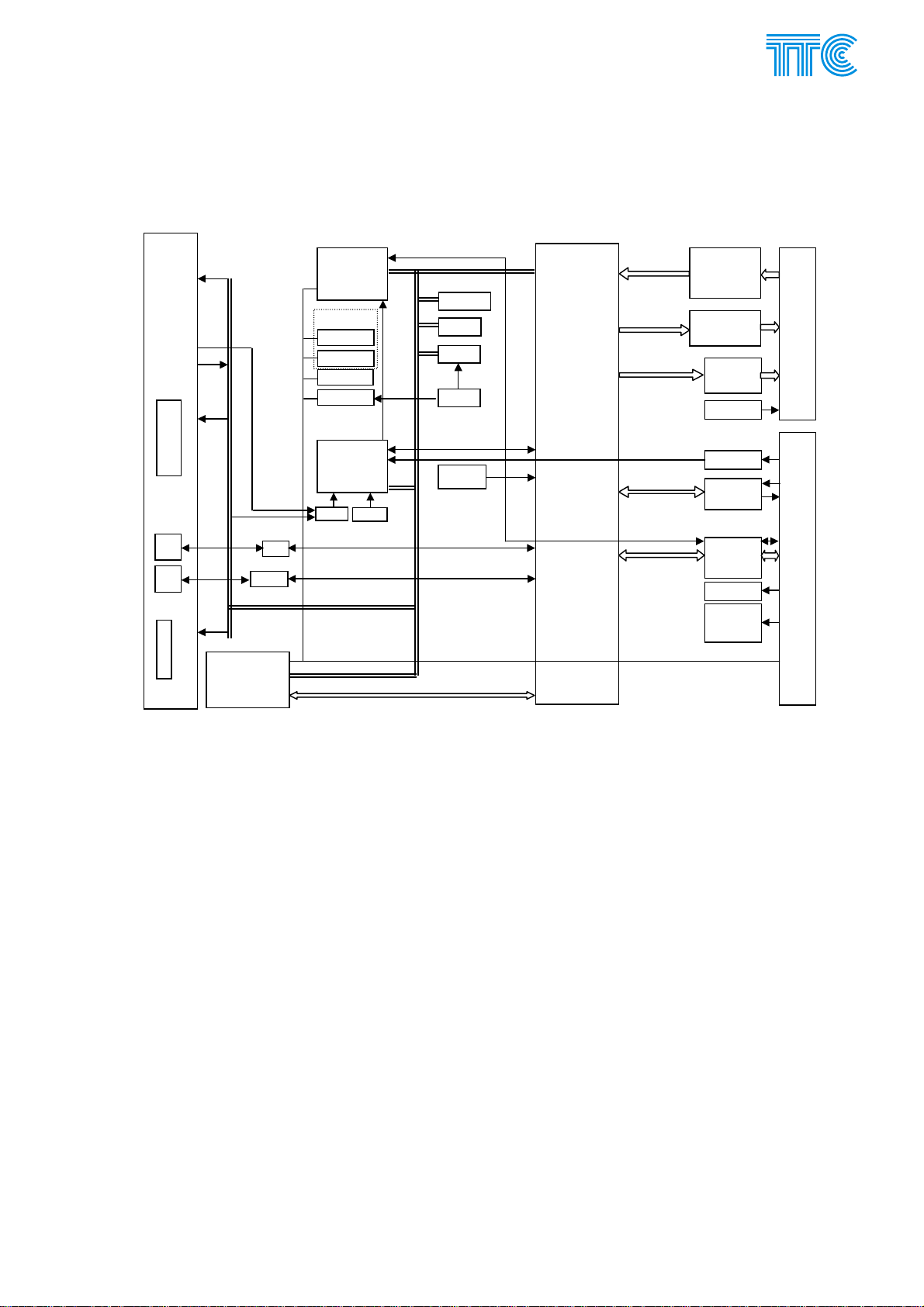
E.1.3 Elementary scheme
Front panel
LEDS
PW,ER,TST
Buttons
Reset
Test
LEDS
LED
in / out
M
LM
LEDS
LM
1
E2
2
submodule
Submodule
interface
V.11
RS232
Microcomputer
cfg
seeprom1
seeprom2
thermometer
real time
CPLD
WD 3V
I2C bus
RST
WD 5V
ddress / Data
buss
SK
MROM-cfg
FLASH
BSRAM
battery
VCO
67 MHz
PLD
Xilinx
INPUT 1-4
INPUT 5-10
QUIT
OUTPUT 1-4
OUTPUT 5-10
ERR1
ERR2
-Ub / -24 V
KJ position
ext. sync.
V.11
internal data
3.3V / 5V
converter
-Ub
5V
5 V
soft
3 V
start
cfg from
backplane
XC202
PW connecte
XC8
unit to backplane connecte
Fig 1 Block diagram of the PBS module
Heart of the unit is PLD Xilinx, which makes all security, time filtering, prolonging, shortening. Microcomputer
is responsible for configuration, communication with management system, log of commands and alarms.
Configuration is stored in two seeprom, can be loaded also from seeprom located at backplane in 6OCH8,
6OCH4. Unit checks 5 V, 3 V and –Ubk used for feeding relays. Switches are used for basic configuration.
Power Channel Modules E-5 446S037.914.14N00
PCM30U, PCM30U-OCH – User's, Operating and Maintenance Manual
E.1.4 Combination and time features
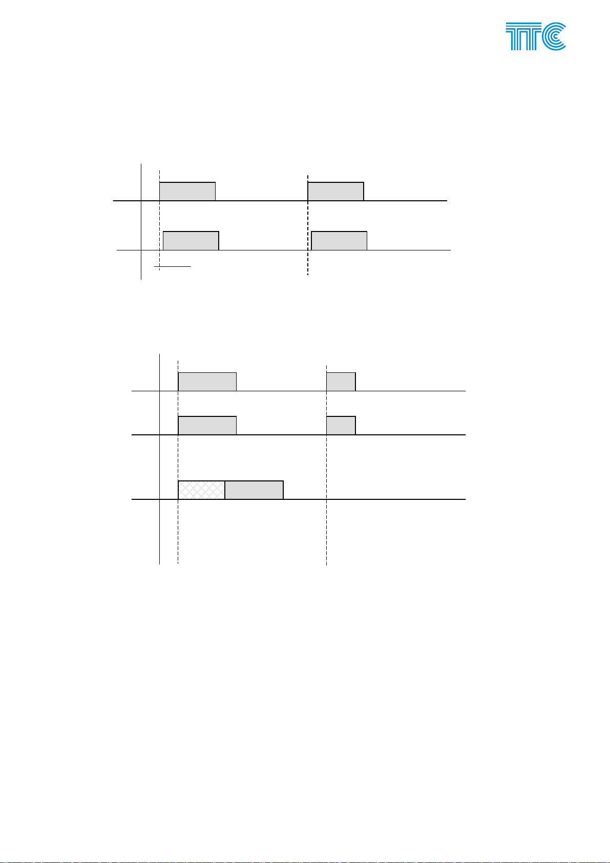
E.1.4.1 Standard function
Input state is transferred to remote unit outputs with minimal transport delay.
Input 1
Output 1
Td
E.1.4.2 Input filtering
Input filtering is minimal presence of command at input required to be transmitted to remote PBS. Shorter
input signals are ignored. Result is transmission delay.
Input 1
Transmission
of input 1 to
remote PBS.
Input filtering
0 ms
Transmission
of input 1 to
remote PBS.
Input filtering
8 ms.
10 ms
10 ms 5 ms
8 ms 10 ms
5 ms
Power Channel Modules E-6 446S037.914.14N00
PCM30U, PCM30U-OCH – User's, Operating and Maintenance Manual
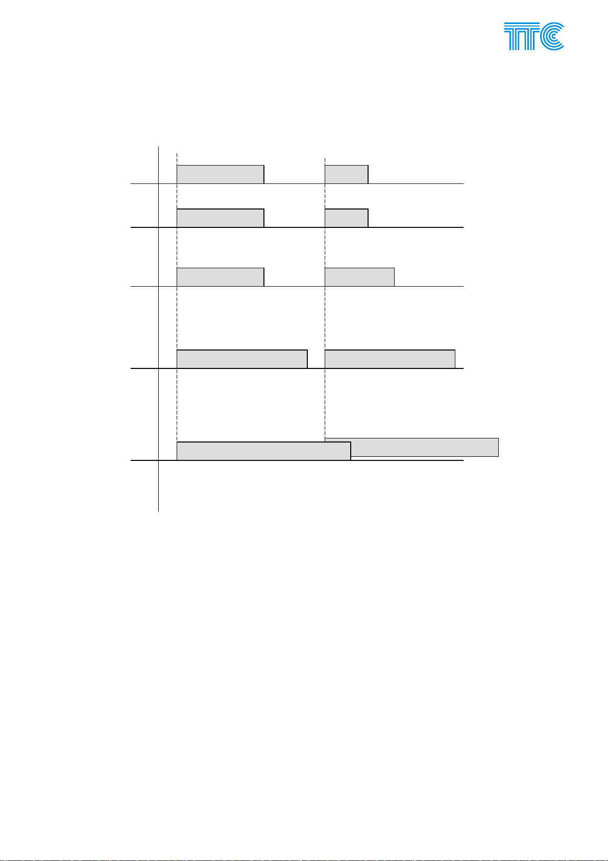
E.1.4.3 Prolongation
This is to ensure minimal duration of transmitting command.
Input 1
Transmission
of input 1 to
remote PBS
Transmission
of input 1 to
remote PBS
Prolongation
to 80 ms
Transmission
of input 1 to
remote PBS
Prolongation
to 150 ms
Transmission
of input 1 to
remote PBS
Prolongation
to 200 ms
100 ms
100 ms
100 ms
50 ms
50 ms
80 ms
150 ms 150 ms
200 ms
200 ms
Power Channel Modules E-7 446S037.914.14N00

PCM30U, PCM30U-OCH – User's, Operating and Maintenance Manual
A
A
A
A
A
A
A
E.1.4.4 And function
Input 1
Input 7
Output 1
Output 7
E.1.4.5 Or function
Input 1
Input 7
Output 1
Output 7
E.1.4.6 And / Or combination
This option is set and applied only at transmitter side. Only pairs input can be (and / or)ed. Pairs are
build from these combinations: 1-7, 2-8, 3-9, 4-10, 5-6, 7-8, 9-10.
PBS 1
IN 2
IN 3
IN 4
IN 5
IN 1
ND/OR
ND/OR
ND/OR
ND/OR
ND/OR
PBS 2
OUT
OUT
OUT
OUT
OUT
1
2
3
4
5
IN 6
IN 7
IN 8
IN 9
IN 10
ND/OR
ND/OR
OUT
OUT
OUT
OUT
OUT
6
7
8
9
10
Power Channel Modules E-8 446S037.914.14N00
PCM30U, PCM30U-OCH – User's, Operating and Maintenance Manual
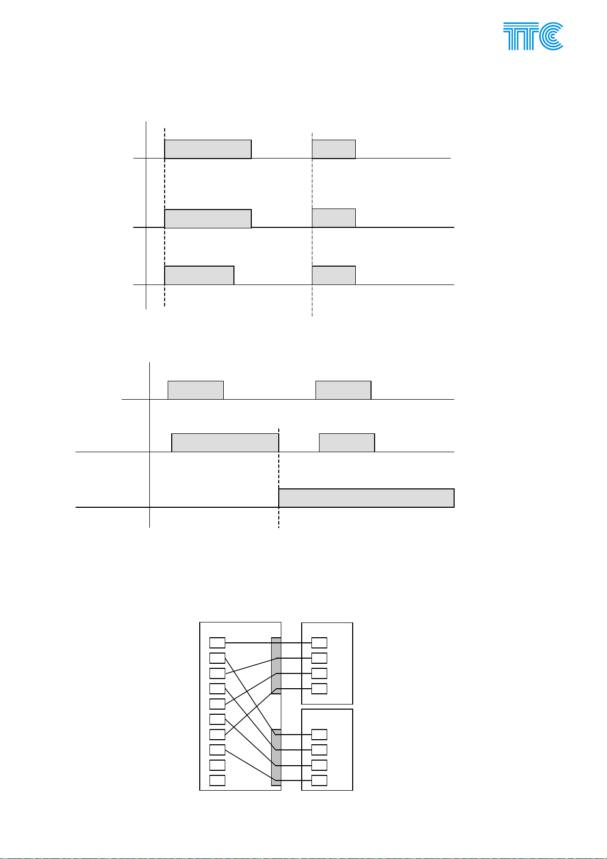
E.1.4.7 Output limiting
Command 1
as received
from
100 ms 50 ms
transmission
path
Output state
of command 1
100 ms
50 ms
without
limiting
Output state
of command 1
80 ms
50 ms
with limiting to
80 ms
E.1.4.8 Acknowledgment function
Input 1
Output 1
Ack
E.1.4.9 PBS to 2x 4PBS
Special interconnection of commands designed for transmission from one PBS to two 4PBS. Function is
performed and selected only et PBS. Odd commands are routed to A group, even commands are routed to B
group. This option requires special firmware and is not recommended for direct tripping, because is it results
in complicated network structure.
PBS 4PBS
1
2
3
4
5
6
7
8
9
10
A
1
2
3
4
B
4PBS
1
2
3
4
Power Channel Modules E-9 446S037.914.14N00
PCM30U, PCM30U-OCH – User's, Operating and Maintenance Manual
E.1.5 Security (in general)
PBS transmits data in 64bit blocks called packets. Block contains state of commands (doubled for 1-6
command), CRC of 12
synchronization are not covered by CRC. Synchronization is spread around whole packet I order to improve
resilience against false synchronization.
Additional security shall be obtained by “repeating” requesting 2 or 4 equal states of received commands to
act at outputs.
This result in following “probability of unwanted command” P
Inputs are periodically (every 500μs @128 kbit/s) sampled and coded into this packet.
E.1.5.1 Continual test
Packets are transmitted and received continually (every 500μs @128 kbit/s), that means both local and
remote PBS are under full check as well as transmission path.
Next more this test uses back acknowledgment bits located in packet. Every received command is
transmitted back to source as an acknowledgment of transmission. This test is performed every 10 ms
E.1.5.2 Button Test
This test is intended to be used at commissioning time or at “troubleshooting procedure”. Purpose is to check
individual LEDs and routing when PBS with “two direction” feature is used.
Test can be initiated only by pressing Test button at unit for time longer then 500 ms. Test cannot be initiated
when command is active. Since it takes some time (approximately 500 ms) to stop the Test, it cannot be
used under full operational mode, because transmission time could not be granted.
th
order, synchronization and management channel. Management channel and part of
.= 3.2 109*p13, where p equals BERR.
uc
PBS1 PBS2
IN 1
IN 10
OUT 1
OUT 10
in / out
discon
nection
button
test
loop
command
back ack
command
permanent
test loop
coding
security
2 packets/ms
(128 kbit/s)
E.1.5.3 Button test sequence
Test initiated by button at PBS1. “Start of Test” record is written to alarm log.
PBS1 disconnects inputs and outputs.
PBS1 transmits “Test state” to PBS2
PBS2 blocks outputs, creates “button test loop” and confirms test state
PBS1 simulates step-by-step individuals commands and check that they come back.
LED indicates command being tested, flashing green LED indicates failure at individual command.
“Test state” must be canceled at both PBS to return to operational state.
“End of Test” - “success” or “failure” record is written to alarm database
Power Channel Modules E-10 446S037.914.14N00

PCM30U, PCM30U-OCH – User's, Operating and Maintenance Manual
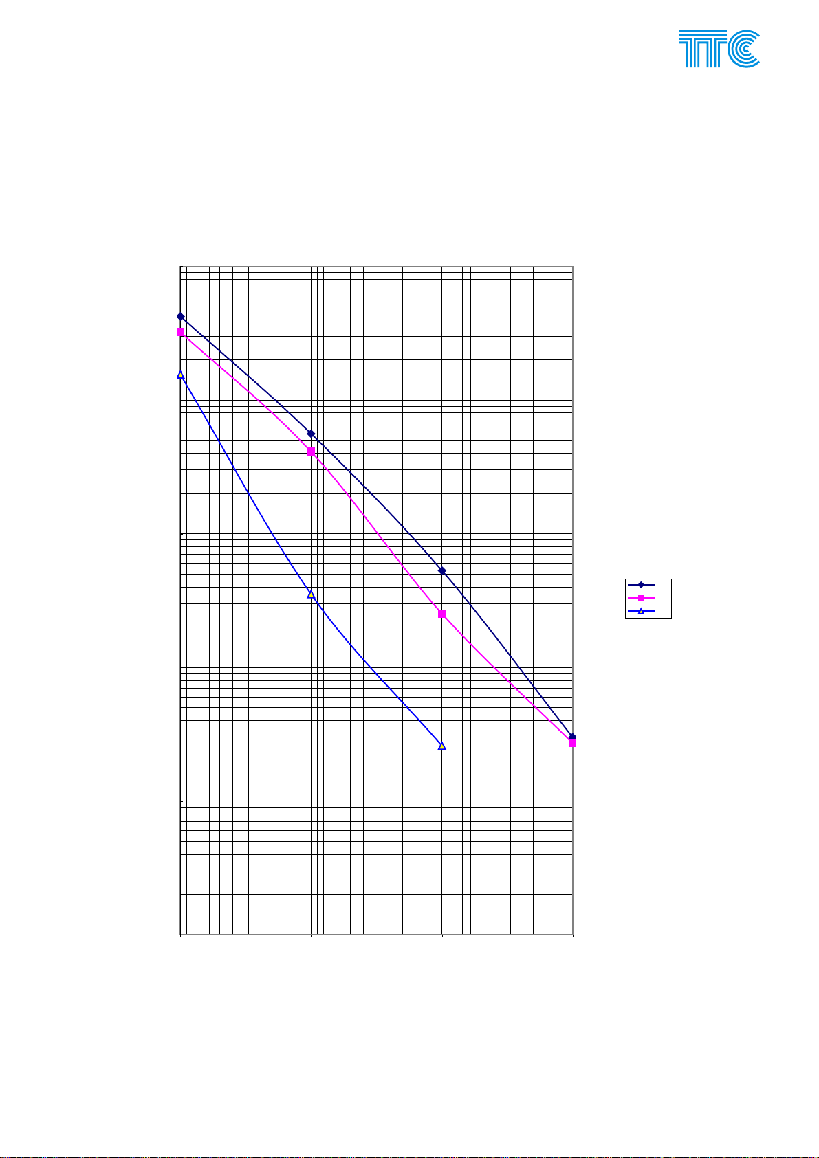
E.1.5.4 Security
Figure below represents calculated probability of unwanted (false) command as a function of bit error
rate for different number of repeats.
1,00E+00
1,00E-03
1,00E-06
1,00E-09
1,00E-12
1,00E-15
1,00E-18
1,00E-21
1,00E-24
1,00E-27
1,00E-30
1,00E-33
1,00E-36
PBSPuc
Puc
PBSPuc2
PBSPuc4
1,00E-39
1,00E-42
BERR
1,00E-041,00E-031,00E-021,00E-011,00E+00
Power Channel Modules E-11 446S037.914.14N00
PCM30U, PCM30U-OCH – User's, Operating and Maintenance Manual
E.1.5.5 Dependability
Figure below represents measured dependability as a function of bit error rate for different To according
to recommendation. To=1,2 means, that command is stated as lost, when delayed more then 1,2 of nominal
transmission time.
Dependability
1,00E+00
1,00E-01
1,00E-02
1,00E-03
1,00E-04
1
Pmc
1,2
1,5
1,00E-05
BER
1,00E-051,00E-041,00E-031,00E-02
Power Channel Modules E-12 446S037.914.14N00
PCM30U, PCM30U-OCH – User's, Operating and Maintenance Manual
A
p
p
p
p
p
p
p
p
p
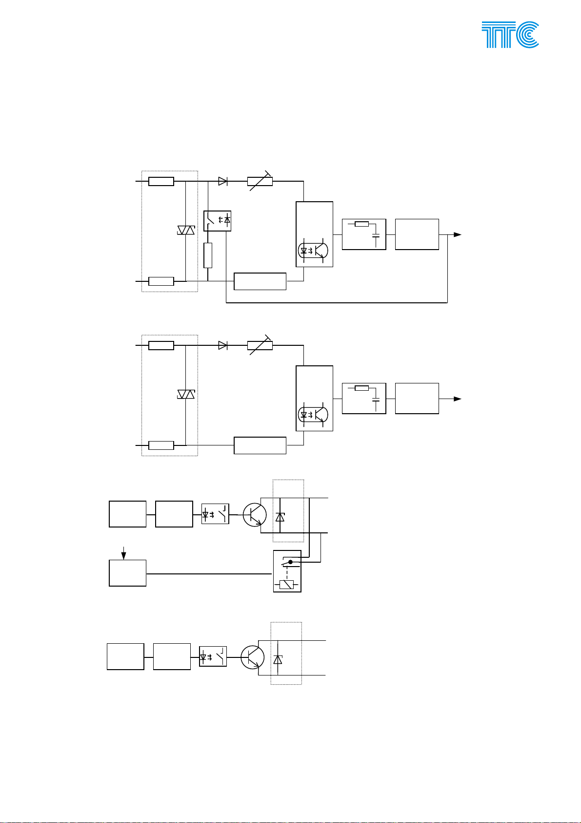
E.1.6 Schematics
E.1.6.1 Inputs and outputs
Input 1 to 4
ut
+ In
Resistor network for
nominal voltage selection
configurable by jumpers
4 kV
and 300 V
protection
- In
ut
Input 5 to 10
ut
+ In
4 kV
and 300 V
protection
- In
ut
dditional load
switched off when
ut > U threshold
U in
Current limiter with
optorelay
Resistor network for
nominal voltage selection
configurable by jumpers
Current limiter with
optorelay
Optocoupler
and
supporting
circuit
Optocoupler
and
supporting
circuit
RC filter to
remove glitches
RC filter to
remove glitches
Logic level
converter
Logic level
converter
I to Xilinx
I to Xilinx
Outputs 1 to 4
-Ubat
Switch ON
accelerate
circuit
Logic level
converter
Level
converter
logic / -Ubat
Outputs 5 to 10
Logic level
converter
Switch ON
accelerate
circuit
Optorelay
Optorelay
Protection
300 V
Protection
300 V
+Out
-Out
+Out
-Out
ut
ut
ut
ut
Fig 2 Schematic of inputs and outputs
Power Channel Modules E-13 446S037.914.14N00

PCM30U, PCM30U-OCH – User's, Operating and Maintenance Manual
j
j
j
r
E.1.6.2 Error outputs ERR1, ERR2
Electronical error output ERR1
Logic level
converter
Switch ON
accelerate
circuit
umper
switch XJ800
Optorelay
umper
switch XJ801
Electromechanical error output ERR2
-Ubat
Level
converter
logic / -Ubat
umper
switch XJ802
Protection
300 V
E.1.6.3 Schematic of internal source –24 V/30 mA
Internal source –24 V/30 mA
Protection
+ ERR1
300 V
- ERR1
+ ERR2
- ERR2
-Ubat -24 V / 30 mA
GND
-24 V regulator
-current
with ove
protection (40 mA)
I sense
U sense
30V
Protection
GND
Power Channel Modules E-14 446S037.914.14N00

PCM30U, PCM30U-OCH – User's, Operating and Maintenance Manual
E.1.7 PBS Technical Parameters
E.1.7.1 General parameters
Number of bi-directional commands 10 (4)
Acknowledge input (ACK) 1
Transmission and security time (Tts)
additional security (repeating) transmission
speed
64 kbps 2 ms 4 ms 8 ms
128 kbps 1 ms 2 ms 4 ms
256 kbps 0,5 ms 1 ms 2 ms
Acting at output time (Ta)
Output Switch on Switch off
1 ÷ 4 1 ms 4 ms
5 ÷ 10 1 ms 1 ms
Complete transmission time is summation of Tts + Ta +Ttp. Ttp is additional delay caused by transmission
path.
HW unit configuration
Unit identification – A direction 4 bit address by switches on the unit
Unit identification – B direction 4 bit address by switches on the unit
nominal input voltage individual jumpers for each command
on / off switch error outputs individual jumpers for each
on / off switch command outputs switch off only on demand while order (assembly option)
SW unit configuration
Input command digital filtering 0÷48 ms ±1 ms
Prolonging of command at input 0÷10 000 ms ±10 ms (0 - 1200 ms)
Shortening of command at output 0÷1 000 ms ±1 ms (0 - 120 ms)
Add, and, blocking at input
Blocking and kvit at output
Capacity of unit‘s command log 1000 records
Capacity of the DORIS command log Depending on the hard disk free space
Counter of transmitted commands
Status indications by LED on panel
Command interface
connector
1x (basic) 2x 4x
±100 ms (1200 – 10 000 ms)
±10 ms (120 – 1000 ms)
Only one function of kvit and blocking can be used,
because of they use commonn input KVIT.
DORIS
Optionally display (0-999)
DORIS Counter of received commands
Optionally display (0-999)
Operation
Error
Test
Command sending (10x LED)
Command receiving (10x LED)
Urgent, non-urgent, service alarm Line interface status (only PWA)
Unspecific error – must be identified by DORIS
DIN 41612 type E Crimp contacts
CFVA 48, type E, 48 pin with grub screws for 10 commands
DIN E 32, type E, 32 pin with grub screws for 4 and 6 commands
Power Channel Modules E-15 446S037.914.14N00

PCM30U, PCM30U-OCH – User's, Operating and Maintenance Manual
E.1.7.2 Inputs (units with serial number F03 and higher)
And units F01, F02 marked with blue round mark described 03
03
Inputs 10+1, optocouplers with galvanic decoupling
Electrical resilience of optocouplers > 4 kV DC / 3,75 kV AC RMS
Electrical resistance against ground, between different
> 100 MΩ / 500 V DC
inputs and outputs
Overvoltage strength against surge 10/700 μs
4 kV
ITU-T K.20
Nominal DC voltage (Un) (selectable by jumpers) 24 V, 48 V, 110 V, 220 V
Command „active“ input voltage tolerance 0,85 ÷ 1,2 Un
Command „non-active“ input voltage tolerance 0 ÷ 0,2 Un
Threshold voltage Uth
Nominal voltage Inputs 1-4 Inputs 5-10, ACK input
Voltage increasing 0,6 ÷ 0,65 Un 0,6 ÷ 0,65 Un Un = 220 V DC
Voltage declining 0,44 ÷ 0,5 Un 0,59 ÷ 0,64 Un
Voltage increasing 0,6 ÷ 0,65 Un 0,6 ÷ 0,65 Un Un = 110 V DC
Voltage declining 0,45 ÷ 0,51 Un 0,59 ÷ 0,64 Un
Voltage increasing 0,6 ÷ 0,65 Un 0,6 ÷ 0,65 Un Un = 48 V DC
Voltage declining 0,46 ÷ 0,52 Un 0,59 ÷ 0,64 Un
Voltage increasing 0,6 ÷ 0,65 Un 0,6 ÷ 0,65 Un Un = 24 V DC
Voltage declining 0,48 ÷ 0,54 Un 0,59 ÷ 0,64 Un
Input hysteresis
Inputs 1-4 Inputs 5-10, ACK input (For all nominal voltages)
0,08 ÷ 0,22 Un 0,005 ÷ 0,03 Un
Threshold level can be customized on demand.
Input current at nominal voltage (Ui=Un)
Selected nominal voltage Inputs 1-4 Inputs 5-10, ACK input
Un = 220 V DC
2,9 mA ±20% 2,6 mA ±20%
Un = 110 V DC 2,9 mA ±20% 2,6 mA ±20%
Un = 48 V DC 2,9 mA ±20% 2,6 mA ±20%
Un = 24 V DC 2,9 mA ±20% 2,6 mA ±20%
Input current before threshold (Ui = 0,995 ÷ 0,999 Uth )
Note increased noise immunity of inputs 1-4
Selected nominal voltage Inputs 1-4 Inputs 5-10, ACK input
Un = 220 V DC 11,8 mA ±20% 1,6 mA ±20%
Un = 110 V DC 6,4 mA ±20% 1,6 mA ±20%
Un = 48 V DC 3,4 mA ±20% 1,6 mA ±20%
Un = 24 V DC 2,3 mA ±20% 1,6 mA ±20%
Input current is electonically limmited at higher voltages and can be customized on demand.
Power Channel Modules E-16 446S037.914.14N00

PCM30U, PCM30U-OCH – User's, Operating and Maintenance Manual
E.1.7.3 Inputs (units with serial number F01, F02)
Inputs 10+1, optocouplers with galvanic decoupling
Electrical resilience of optocouplers > 4 kV DC / 3,75 kV AC RMS
Electrical resistance against ground, between
> 100 MΩ / 500 V DC
different inputs and outputs
Overvoltage strength against surge 10/700 μs
4 kV
ITU-T K.20
Nominal DC voltage (Un) (selectable by jumpers) 24 V, 48 V, 110 V, 220 V
Command „active“ input voltage tolerance 0,85 ÷ 1,2 Un
Command „non-active“ input voltage tolerance 0 ÷ 0,2 Un
Inputs 1-4 Inputs 5-10, ACK input
Voltage increasing 0,6 ÷ 0,75 Un 0,6 ÷ 0,75 Un Threshold voltage Uth
Voltage declining 0,45 ÷ 0,6 Un 0,58 ÷ 0,73 Un
Hysteresis 0,08 ÷ 0,22 Un 0,008 ÷ 0,02 Un
Threshold level can be customized on demand.
Input current at nominal voltage (Ui=Un)
Selected nominal voltage Un Inputs 1-4 Inputs 5-10, ACK input
220 VDC
3,0 mA ±20% 2,5 mA ±20%
110 VDC 3,0 mA ±20% 2,5 mA ±20%
48 VDC 3,0 mA ±20% 2,5 mA ±20%
24 VDC 3,0 mA ±20% 2,5 mA ±20%
Input current before threshold (Ui = 0,995 ÷ 0,999 Uth )
Note increased noise immunity of inputs 1-4
Selected nominal voltage Un Inputs 1-4 Inputs 5-10, ACK input
220 VDC 12,5 mA ±20% 1,7 mA ±20%
110 VDC 6,9 mA ±20% 1,7 mA ±20%
48 VDC 3,7 mA ±20% 1,7 mA ±20%
24 VDC 2,4 mA ±20% 1,7 mA ±20%
Input current is electonically limmited at higher voltages and can be customized on demand.
Power Channel Modules E-17 446S037.914.14N00

PCM30U, PCM30U-OCH – User's, Operating and Maintenance Manual
E.1.7.4 Outputs
Outputs
voltage drop at max. load
typical value max. value
1-4 electronic-mechanic switch 100 mV 200 mV
5-10 electronic switch 1 V 1,4 V
Electrical resistance against ground and between
> 100 MΩ / 500 V DC
different outputs and inputs
Overvoltage resilience against surge 10/700 μs
1 kV
ITU-T K.20
Electrical resilience of command contacts
Relay contacts / ground > 4 kV DC / 3,75 kV AC RMS
Open relay contacts 280 V DC Limited by electronic switch protection
Maximum contact load
Switched
voltage V DC
Permanent
condition A DC
Closed/open
contact
current A DC
L/R=40 ms
Open/closed
contact current
A DC, 0,2 s
L/R=10 ms
Outputs 1-4 5 ÷ 280 V 4 A 4 A 30 A
Outputs 5-10 5 ÷ 280 V 1 A 1 A 1,5 A
Electronic alarm relay 5 ÷ 280 V 1 A 1 A 1,2 A
Electromechanical alarm relay
24 V 4 A 1,2 A
4 A
48 V 1,5 A 0,5 A
60 V 1 A 0,4 A
110 V 0,6 A 0,22 A
220 V 0,4 A 0,1 A
280 V 0,3 A 0,06 A
Failure relays
electromechanical switch ERR2 Optionally on/off switch
electronic switch ERR1 Optionally on/off switch
Electrical resilience of alarm relays
Relay contacts / ground > 4 kV DC
Relay contacts open 280 V DC Limited by protection
Output switches lifetime Switches w/o load Switches at maximum load
Outputs 1-4 >1x10
Outputs 5-10 > 1x10
Electronic alarm relay > 1x10
7
12
12
Electro-mechanical alarm relay > 1.5x10
7
>1x10
> 1x10
> 1x10
> 5x10
7
12
12
5
Internal source for contacts -24 VDC / 30 mA against ground
Power Channel Modules E-18 446S037.914.14N00

PCM30U, PCM30U-OCH – User's, Operating and Maintenance Manual
E.1.8 Front panel
E.1.8.1 PWA variant .1.8.1 PWA variant
Display (optional)
Test button
Long pushing the button
starts automatic
transmission test of
commands 1÷10
M interface connector
(management channel)
for control equipment
RB ant M
interconnection
Reset button
Pres and release to
reset PBS
LM – Local
Management channel
interface
Interface K1 of
submodule (PWA option)
Interface K2 of
submodule (PWA option)
PBS
Power Channel Modules E-19 446S037.914.14N00

PCM30U, PCM30U-OCH – User's, Operating and Maintenance Manual
E.1.8.2 Channel module variant
Display (optional
Test button
Long pushing the
button starts
automatic
transmission test
of commands 1÷10
Reset button
Pres and release
to reset PBS
PBS
Power Channel Modules E-20 446S037.914.14N00

PCM30U, PCM30U-OCH – User's, Operating and Maintenance Manual
E.1.9 LED indication
E.1.9.1 LED - PWA variant
PWR
•
Green
Operational
state
Dark
•
No power or
“out of order!
TEST
•
Orange
Test in
progress
Orange -
•
Test error
flashing
IN
•
Orange
Input command
active
Orange
and test
Orange –
flashing
•
Command being
tested
•
Test error at this
command
and TEST
LM – GREEN
Activity at LM interface
1, 2
Green Line interfaces in
operational state
Yellow
•
High BER, slip at
line interface 1,2
Yellow flashing
•
Loop at line
interface 1,2
•
Laser
permanently ON
Red Loss of signal
PBS
ERR - Urgent alarm
•
Red
Transmission
protocol error
•
Identification error
•
Opposite PBS error
(duplex mode)
Red –
flashing
•
Invalid
configuration
quickly
Red –
•
Not specified
flashing
slowly
OUT
Orange
•
Output command
active
Orange
and test
Orange –
flashing
•
Command being
tested
•
Test error at this
command
and TEST
E2 – other alarms
•
Red
Single bit error (light
prolonged to 100 ms)
•
-48 V DC for relays
and bias source below
threshold
•
Opposite PBS error
(simplex mode)
Yellow
flashing
Service alarm
•
Data signal loop
detected
Green Not specified
Power Channel Modules E-21 446S037.914.14N00

PCM30U, PCM30U-OCH – User's, Operating and Maintenance Manual
E.1.9.2 LED - Channel module variant 2 LED - Channel module variant
ERR - Urgent alarm
PWR
Green
• Operational
state
Dark • No power or
“out of order!
TEST
Orange
• Test in
progress
Orange -
• Test error
flashing
Red
Red –
flashing
quickly
Red –
flashing
slowly
• Transmission protocol
error
• Identification error
• Opposite PBS error
(duplex mode)
• Invalid configuration
• Not specified
IN
Orange
Orange
and test
Orange –
flashing
and TEST
• Input command
active
• Command being
tested
• Test error at this
command
PBS
OUT
Orange
• Output command
active
Orange
and test
Orange –
flashing
• Command being
tested
• Test error at this
command
and TEST
E2 – other alarms
Red
• Single bit error (light
prolonged to 100 ms)
• -48 V DC for relays
and bias source below
threshold
• Opposite PBS error
(simplex mode)
Yellow
flashing
Service alarm
• Data signal loop
detected
Green Not specified
Power Channel Modules E-22 446S037.914.14N00

PCM30U, PCM30U-OCH – User's, Operating and Maintenance Manual
E.1.10 PBS shorters and mechanical configuration
Jumper Meaning
XC1 Boundary scan connector
XC2, XC3 Line interface submodule connector
XC5 Display connector (optional)
XC6 LM local interface connector
XC7 M interface connector (management channel)
XC201 Connector for connecting of commands and alarm contacts
XJ2, XJ5 GND
XJ3 +5V
XJ4 +3,3V
XJ6 AUX1 – factory test point
XJ7 AUX2 – factory test point
XJ8 AUX4 – factory test point
DS1 Program memory
E.1.10.1 Setting the functioning of ERR1 alarm opto-relay
alarm = cloth
E.1.10.2 Setting the functioning of ERR2 alarm elektromechanical relay
alarm = cloth XJ802 1-2
alarm = open XJ802 2-3
E.1.10.3 Setting command nominal input voltage
command jumper 24 V 48 V 110 V 220 V
1 XJ200 2-3 1-2, 3-4 1-2 —
2 XJ220 2-3 1-2, 3-4 1-2 —
3 XJ240 2-3 1-2, 3-4 1-2 —
4 XJ260 2-3 1-2, 3-4 1-2 —
5 XJ280 2-3 1-2, 3-4 1-2 —
6 XJ300 2-3 1-2, 3-4 1-2 —
7 XJ320 2-3 1-2, 3-4 1-2 —
8 XJ340 2-3 1-2, 3-4 1-2 —
9 XJ360 2-3 1-2, 3-4 1-2 —
10 XJ380 2-3 1-2, 3-4 1-2 —
Qvit XJ400 2-3 1-2, 3-4 1-2 —
Gray marked fields indicates factory default settings.
E.1.10.4 Configuration switches
SA3(1..4) Unit identification for command group transmitted to A direction
SA4(1..4) Unit identification for command group transmitted to B direction
SA7(1..4)-SA6(1..2)
SA6(3) Lock configuration of PBS functions to prevent inappropriate actions from the
SA6(4) Lock configuration of PWA functions to prevent inappropriate actions from the
SA5(1..4) For future use. Not assembled after January 2009
XJ800 2-3
XJ801 1-2
XJ800 1-2 alarm = open
XJ801
M management address in binary form (2
M = SA7(1) x 1 + SA7(2) x 2 SA7(3) x 4 + SA7(4) x 8 SA6(1) x 16 + SA6(2) x 32
management system
management system
2-3
0÷25
)
Power Channel Modules E-23 446S037.914.14N00

PCM30U, PCM30U-OCH – User's, Operating and Maintenance Manual
A
A
A
A
E.1.11 PBS layout
S
3
S
4
SA
5
S
6
S
7
SA7
R116
R117
R118
R119
1
OFF
M management
address in binary form
Configuration lock - protection
3 4
SA6
1 2 3 4
4
OFF
4
For future
use
SA5
1 234
OFF
SA4
1 2 3 4
4
OFF
SA3
1 2 3 4
4
OFF
Direction of view:
4
From connector
XC201 to front panel
Identification for
group A
Identification for group B
against bad manipulation
pin 3 - PBS functions
pin 4 - PWA functions
Fig 3 Setting points of the PBS module
Power Channel Modules E-24 446S037.914.14N00

PCM30U, PCM30U-OCH – User's, Operating and Maintenance Manual
E.1.12 XC201 Connector pin description
a2 +IN1
a4 -IN1
a6 +IN2
a8 -IN2
a10 +IN3
a12 -IN3
a14 +IN4
a16 -IN4
a18 +IN5
a20 -IN5
a22 +IN6
a24 -IN6
a26 +Q
a28 -Q
a30 -24V
a32 GND_0V
c2 +IN7
c4 -IN7
c6 +IN8
c8 -IN8
c10 +IN9
c12 -IN9
c14 +IN10
c16 -IN10
c18 +OUT7
c20 -OUT7
c22 +OUT8
c24 -OUT8
c26 +OUT9
c28 -OUT9
c30 +OUT10
c32 -OUT10
e2 +OUT1
e4 -OUT1
e6 +OUT2
e8 -OUT2
e10 +OUT3
e12 -OUT3
e14 +OUT4
e16 -OUT4
e18 +OUT5
e20 -OUT5
e22 +OUT6
e24 -OUT6
e26 +ERR1
e28 -ERR1
e30 +ERR2
e32 -ERR2
Command 1 input
Command 2 input
Command 3 input
Command 4 input
Command 5 input
Command 6 input
Acknowledge input
Minus pole of bias voltage source –24 V/30 mA
Ground
Command 7 input
Command 8 input
Command 9 input
Command 10 input
Command 7 output
Command 8 output
Command 9 output
Command 10 output
Command 1 output
Command 2 output
Command 3 output
Command 4 output
Command 5 output
Command 6 output
Alarm opto-relay output
Alarm electromechanical relay output
Power Channel Modules E-25 446S037.914.14N00

PCM30U, PCM30U-OCH – User's, Operating and Maintenance Manual
E.1.13 Recommended wires and tools for connector XC201
Connector with crimp contacts
32
e
c
a
2
Wire diameter for crimping into FC3 0,5 – 1,5 mm² (20-16 AWG)
Outer diameter of insulation 1,6 - 2,8 mm
3,5-4
Insulation stripping length 3,5 to 4 mm
Removal tool TTC 1900274
Connector with grub screws contacts (32 screws)
32 2
e
c
a
Recommended wire diameter (1 wire or cable) 0,22 – 2,5 mm² (24-14 AWG)
8±0,5
Insulation stripping length 8 mm ± 0,5 mm
Recommended screwdriver 3,5×0,5 mm
Recommended tightening torque 0,6 Nm
Power Channel Modules E-26 446S037.914.14N00

PCM30U, PCM30U-OCH – User's, Operating and Maintenance Manual
E.1.14 Trouble shooting
LED Status Meaning note
Green Equipment operational, feeding OK PWR
Off 1. Check power supply NP107,PBS requires –48 V DC,
+5 V DC
2. Check program memory if correctly installed (after
upgrading FW)
3. Check if PBS correctly installed (after removing)
4. Replace PBS
5. Call service
ERR
IN 1÷10
OUT 1÷10
Off Operational state
Off - expect Red Check if “time to assert alarm” is not longer then error conditions
Red
Red - flashing Reconfigure unit. Fill all configuration cards in Doris and “set all”
Orange Test in progress. Test may be initiated from opposite unit TEST
Orange - flashing Test not successfully completed. Press shortly TEST button to
Off Operational state LM
Green Active communication at LM interface. Disconnect cable. Active
Yellow Input signal has been recognized as a active command
Yellow - expect Off Check prolongation if not to long
Yellow – flashing
quickly
Off - expect Yellow 1. Check voltage in station
Yellow Command active
Yellow - expect Off Check Kvit
Yellow – flashing
quickly
Off - expect Yellow Check limiting at output
Opposite then you
expect
1. Check 2 Mbps stream (CJAB must be green)
2. Check PBS identification (Doris will show urgent alarm
“Identification mismatch”)
3. Check PBS number of used timeslots (commons settings
is 2) and time slot arrangement (common is interlaced)
4. Check originating timeslot (must be the same as in
opposite unit, when cross-connect not used)
5. Check opposite PBS
6. Be sure, that cross-connect is OK
7. Replace PBS
8. Call service
acknowledge “test fail”. Search IN and OUT led‘s for flashing
ones, to see where test failed. Check routing commands a
membership in groups (A, B) at this and opposite PBS‘s
LM communication disables communication with Doris at M
interface
When TEST Yellow – Test failed at this command.
Command not successfully transmitted. Check cross-connect.
Try test.
2. Check voltage configuration jumpers
3. Check time filtering if not longer then commands
When TEST Yellow – Test failed at this command.
1. When ERR is Red, PBS may remember pre-error state or
return to idle.
2. Check AND and OR function at inputs.
*1)
*1)
Power Channel Modules E-27 446S037.914.14N00

PCM30U, PCM30U-OCH – User's, Operating and Maintenance Manual
1, 2
E2
*1) When changing PBS, be sure that it has the same HW and FW configuration.
Green Line interfaces 1,2 in operational state
Yellow High BER, slip at line interface 1,2
Check synchronization
Yellow - flashing Loop at line interface 1,2.
Red Loss of signal
Check cables, cooperating equipment
Red Urgent alarm
Single bit error (light prolonged to 100 ms)
1. Check synchronization – single errors may be caused by
slips.
2. Internal battery voltage under tolerance (below 40 V DC)
Green Non Urgent alarm
Yellow flashing Service alarm
“Data signal in loop detected”
1. Check loop id. It must be different at opposite PBS‘s.
2. Check data path for loops (CJAB flashes), cooperating
equipment
E.1.15 Tolerance mask and example of measured hysterezis for 2nd
input
(before adjustment inputs to 0,6 – 0,65 Un)
Power Channel Modules E-28 446S037.914.14N00

PCM30U, PCM30U-OCH – User's, Operating and Maintenance Manual
E.2 RO4
The RO4 unit in the PCM30U-OCH is responsible for the two-way transmission of two analogue signal
channels at a frequency of 50 Hz with accurate transmission of phase and amplitude. This transmission can
serve for the two-way connection route of the power line comparison protections or for one-way secure
transmission of the sychronisation signal with a constant voltage amplitude with accurate transmission of
phase for power unit synchronisation. The security of the synchronisation signal is provided by the return
control signal, with which the voltage and phase of the signal being transmitted is compared with the control
signal, which was transmitted back from the signal’s place of delivery.
The work of the unit in its function of transmission of comparison protections or transmission of the
synchronisation signal is controlled by jumpers on the unit and by setting, using the DORIS management
system.
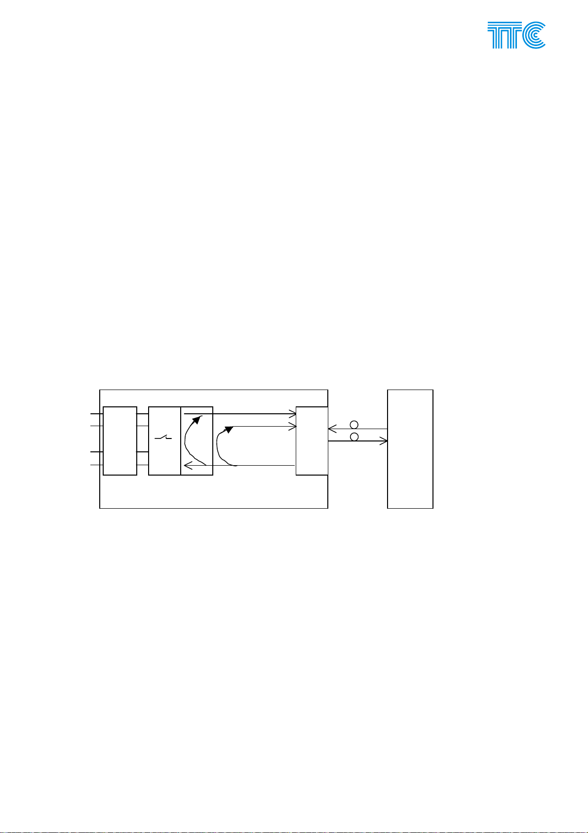
E.2.1 Description of the function of the RO4 unit
The unit is composed of 50 Hz interface circuits, A/D an D/A converters, circuits for insertion in the PCM
framework, Xilinx control circuits and a microcontroller (See Fig. 4 – block diagram of the RO4 unit). The
RO4 unit processes two 50 Hz two-way analogue signals, with limit up to 2800 Hz. Each signal has a
transmitting and receiving directions. The analogue signals of the comparison protection are connected to
the RO4’s four terminals: two for the input (transmitting direction) and two for ouptut (receiving direction).
During transmission of the one-way synchronisation signal for power unit synchronisation, the return channel
is dedicated to the feedback control signal.
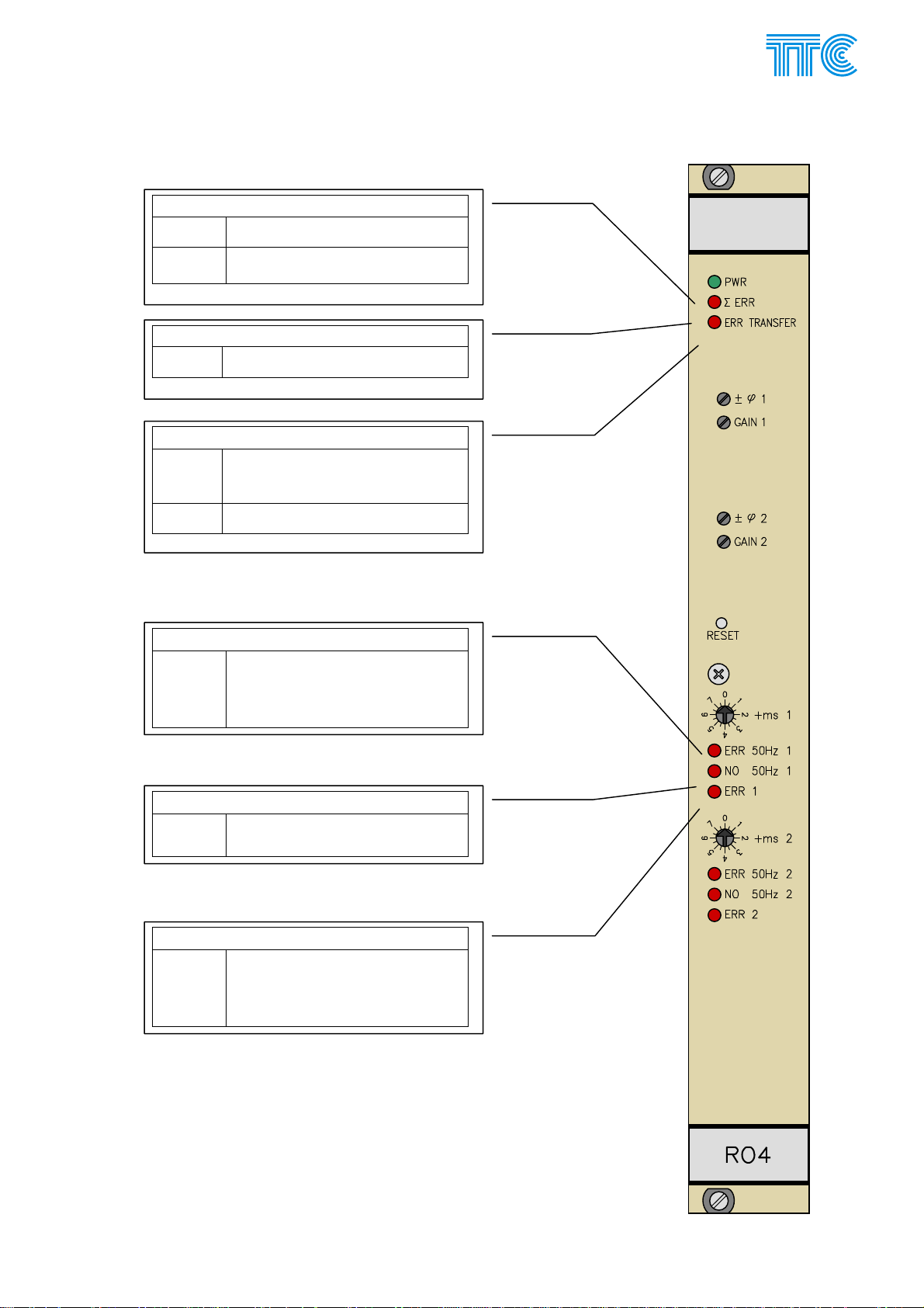
An ‘error’ relay output contact is separately (isolatedly) connected to each channel’s separate pair of
terminals. The ‘out-of-oder’ relay indicates error or interruption of the connection route (the red ERR
TRANSFER) optic diode and, as an option, also a decrease in the transmitted voltage under the preset level
in the respective channel (the NO 50HZ 1 or NO 50HZ 2 red optic diode) or an error identified by the
feedback control signal (the ERR50HZ 1 or ERR 50HZ 2 red optic diode). Using the unit’s jumpers, the make
and break contact of the ‘error’ relay can be preset for error signalling by closing or opening the contact. A
fault is signalled by closing or opening the error contact each time simultaneously on both transmission ends.
Fault on the 1
red diode (see above), while on the opposite side the red ERR 1 or ERR 2 diodes turn on, and if there is a
fault or interruption of the transmission route, the ERR TRANSFER red optidiode also turns on. In addition,
each of the faults (or both simultaneously) is signalled at another pair of terminals by a combined fast
(through the optic relay) fault message Σ ERR (by opening the optic relay) on both ends of the transmission.
The active combined fault signal Σ ERR is indicated by the turning-n of the red Σ ERR optic diode on the
units’ panels – again on both transmission ends.
The presence of supply voltage in the unit is signalled by the green PWR optic diode on the panel of the
respective unit. For appropriate functioning of the unit (attainability of a maximum output voltage level at the
maximum signal load of the 50 Hz signal output), it is necessary to provide a feed voltage Ubat above -43 V,
i.e. 48 V – 10% (a feed voltage of -48 V-15%, i.e. -41 V suffices for the operation of the remaining units). A
decrease in the Ubat voltage under -43 V is therefore indicated by the flashing of the green PWR optic diode
without announcing a fault through the fault contacts (“non-urgent alarm”). The only impact on the work of
the unit is a reduction of maximum amplitude 50Hz output signal at the maximum load. An increase in the
unit’s temperature above +75°C is signalled in a similar way (as non-urgent alarm) by the flashing of the
PWR optic diode. The exact Ubat voltage level or the unit’s temperature can be determined by the DORIS
supervision system.
E.2.1.1 RO4’s transmitting direction (into transmission path)
Each RO4 channel’s 50 Hz input is symmetric and has two-level protection against interfering voltage, using
arresters and transils. This protection is provided between the input conductors in the transverse direction
and also between each of the two conductors and the unit’s ground, i.e. the ground of the PCM30U-OCH
station. The transmitting direction is galvanically separated from the unit’s other circuits by a transformer with
a 4 kV isolation strength. The input voltage is transferred to a lower value through a miniature transformer
T100 (0.35 VA) and is further transmitted through a voltage separator (adustable by means of jumpers at
XJ102) to a A1 amplifier. With jumpers at XJ102 it is possible to select the maximum 50 Hz input’s voltage of
70 Vrms or 110 Vrms (with fine tuning by a RP100 trimmer during the activation of the unit). The related
st
or 2nd channel is signalled on the side where the fault arose by turning on the respective fault
Power Channel Modules E-29 446S037.914.14N00

PCM30U, PCM30U-OCH – User's, Operating and Maintenance Manual
circuit of the LP1 low-pass filter limits the transmitted frequency band to 2.8 kHz to make it possible to
reliably transmit fast transition phenomena at high short-circuit currents on extra high voltage lines.
The analogue signal of both the channels being transmitted is then conducted to a 4-level digital 10-bit A/D
converter. In addition to the converter’s two analogue inputs for the 1
st
and 2nd 50Hz channels being
transmitted, a third input is also used, serving for the measurement of voltage at the source battery -Ubat
(supervised by the DORIS system). Ther fourth analogue input of the A/D converter is not used. Within one
PCM framework – 125 µs – two different samples are taken from each channel within intrvals of 62.5 µs. The
50 Hz analogue signal’s sampling frequency is 16 kHz, i.e. twice the telephone channel’s sampling
frequency. This provides a higher accuracy of transmission at short circuit in the protected line, where the
50 Hz signal abruptly changes shape and amplitude. The -Ubat DC signal is sampled at a 125µs frequency.
However, 8 bits are transmitted and therefore, in the unit’s comparison protection mode
, the 10bit signal is
first digitally compressed to 8 bits. As a result, even the low voltage levels of the 50Hz input voltage are
transmitted with a maximum accuracy. In the unit’s synchronisation mode
, only the upper 8 bits are used and
are not compressed (the lower two bits for the low voltage levels are left out) because a signal that is
constant in terms of amplitude whose magnitude is close to the maximum input level (and compression
would degrade it) is used almost exclusively. The -Ubat direct current signal is sampled at 8 bits without
compression and is displayed in the management system.
The unit communicates with the opposite unit through a slow data channel in TS16. The basic information on
the state of the unit is transmitted in this channel. Also transmitted in this channel, for security’s sake, is
identification to prevent false action in an unwanted loop on the route and a wrong TS interconnection.
In RO4’s transmitting direction, there are also circuits of the feedback control signal ZK for analogue
comparison of the voltage and phase of the signal transmitted with the control signal, which was transmitted
back from the signal delivery place in the “Synchronisation Signal Transmission” function. An analogue
comparison circuit is used, assessing the voltage and phase difference of the two signals with sensitivity
optimised at about ± 8 Vrms from the 100 Vrms of the output voltage and at about ± 0.45 ms, i.e. an about ±
8° difference in phase. The output signal of the comparison circuit is time-filtered through a circuit with a time
constant of about 200 ms.
E.2.1.2 RO4’s receiving direction The input of the RO4 is the receiving bus, “BUS RECEIVING” 2 Mbit/s. The circuit of the gate array PLD-
XILINX identifies and reads the content of the respective channel intervals along which the digitally encoded
signal is transitted from the opposite station of PCM30U-OCH. If necessary, the 2x8 bit sequence of both the
transmitted channels and of the -Ubat battery voltage signal (if compressed) is decompressed in the XILINX
circuit to 2x10 bits for the dual 10bit D/A converter. If the signal is not compressed, the 2x8 bits received are
directly used.
Each channel’s signal can be delayed by digital setting of the delay in the receiving direction, using the
switch on the unit’s panel +ms1 (+ms2) by steps Δt = 0.5 ms within the range of 0 ms – 7.5 ms. In addition, it
is possible, using jumpers at the XJ1, to set an additional digital delay of +8 ms or +16 ms. It is also possible
to finely tune the delay or phase lead (the function is adjustable with XJ105, XJ205 jumpers) of the
transmitted 50 Hz signal using the analogue correction phase link continuously adjustable by means of the
resistor trimmer ±ϕ1 (±ϕ1) on the panel of each channel within the range of ±0 ms to ±0.5 ms. The analogue
delay or phase lead is in fact a phase shift performed by the analogue phase corrector, which causes no
change to the actual time delay in signal transmission (see !!! Note).
The digital signal of both analogue channels can be checked (in an adjustable manner, using DORIS) for
decrease of the respective 50Hz analogue voltage under a certain selected limit.
The analogue signal from the D/A converter is filtered through the LP2 low pass, like in the transmitting
direction. The related circuit of the A2 amplifier with a potentioneter to regulate amplification is used for
setting the output U2 voltage to the maximum value of up to 50 Vrms or up to 100 Vrms (the range of up to
50 Vrms or 100 Vrms is adjustable, using jumpers at XJ103, XJ203) at the output from the TR2 output
transformer at a maximum excitation. The A3 amplifier is a power amplifier working in the AB class. It is
protected against short circuit at the output of the TR2 output transformer. The supply voltage of the A3
amplifier is DC -48 V ± 10% (external supply voltage).
The TR2 transformer, dimensioned to 10 VA, is used at 5 VA at the maximum, with respect to the reliability
of the equipment. It provides symmetric output and galvanic separation with an isolation voltage of 4 kV. The
output of the receiver of the RO4 unit is protected against interfering voltage in the same manner as input in
the transmitting direction.
Power Channel Modules E-30 446S037.914.14N00

PCM30U, PCM30U-OCH – User's, Operating and Maintenance Manual
The output power can be doubled, if necessary, by parallel combination of the outputs of both power
amplifiers for a maximum output power capacity of up to 10 VA (setting C in technical parameters).
______________________________________________
!!! Note: Digital delay (switch +ms1, +ms2) may not be used in a unit set for the “Comparison Protection” function,
because an actual time delay is involved, which would then cause delayed response to overvoltage or short circuit on the
protected power line (analogue delay or phase lead is in fact phase shift through the analogue corrector of phase, which
does not cause any change to the actual time delay in the signal transmission).
______________________________________________
Power Channel Modules E-31 446S037.914.14N00

PCM30U, PCM30U-OCH – User's, Operating and Maintenance Manual
E.2.2 Technical parameters
Two-way transmission of analogue signal at a frequency of f = 50 Hz of two linksof
comparison protections of the DLN910, S103B, S105 type
Compartive
protections – setting
A
max: 2x5 VA)
(P
OUT
One-way transmission of two routes of the 50Hz synchronisation signal with a constant
voltage amplitude and exact phase for synchronisation of the power plant units with the
frequency and phase of the region (substation)
One-way transmission of one link of the 50Hz synchronisation signal with a constant
voltage amplitude and exact phase for synchronisation of the power plant units with the
frequency and phase of the region (substation) with parallel connection of both power
amplifiers for the doubling of the maximum output power of one channel from 5 VA to
Synchronizing of
generators – setting
B
max: 2x5 VA)
(P
OUT
Synch. of generators
– dobled amplifier
Setting C
max: 1x10 VA)
(P
OUT
10VA, at an OUT max of 100 V AC
Maximum input voltage of the signal 50Hz (setting A, B, C) 70 or 110 V AC
Maximum output voltage, 50Hz, up to a load of:
Phase stability of the output voltage, better than
2 kΩ or 5 kΩ: setting A)
2 kΩ or 5 kΩ: setting B)
1 kΩ (doubl. ampl. setting C)
50 or 100 V AC
100 V AC (5 VA)
100 V AC (10 VA)
°
/ Hz
2.5
Amplitude stability of the output voltage ± 3 V AC
Amplitude distortion at output level decreased by 20 dB
Harmonic distortion of the output voltagte
Crosstalk ratio between adjacent subchannels
Signal to noise ratio (to rated output level in idle channel)
Input impedance options for the 50Hz signal
high
medium – (for DLN910)
low – for S103B, S105)
< 1 dB
< 5%
> 60 dB
> 60 dB
> 50 kΩ
± 10%
5 kΩ
2 kΩ
± 10%
Time of 50Hz signal transmission without additional setting of delay about 0.3 ms
Delay setting in each channel’s transmitting direction, using dig. delay switch at the
0 ms – 23.5 ms
unit’s panel, in jumps of Δt = 0.5 ms within the range of:
Setting the delay/phase lead (function is continuously adjustable with jumpers on the
unit), using an analogue correction phase link (continuously adjustable by the
resistance trimmer on the unit’s panel) in each channel’s transmitting direction, within
0.05 ms to
0.4 ms to ± 5 ms
± 0.5 ms
the range of:
Maximum cross section of external cable conductors connected to the terminal blocks 2 mm2
Mechanical break/make contact of the error relay (with jumper-adjustable function of the
“break” or “make” contact), supplied with direct current from a DC voltage source
0.4 A / 250 V DC to
5 A / 24 V DC
located in the control centre room, its maximum contact current level being indirectly
proportional to the given voltage level
Electrical strength of the input and outpt terminals of the analogue signal and the
2 kV / 1 min AC
electrical strength of the fault signalling terminals
Resistance of the input and output terminals of the analogue signal against overvoltage
5 kV DC
wave whose shape is described in the EN 334000 Standard – 10 ms / 700 ms
Resistance of the fault signalling terminals against overvoltage wave as referred to above
1 kV DC
Power Channel Modules E-32 446S037.914.14N00

PCM30U, PCM30U-OCH – User's, Operating and Maintenance Manual
d
E.2.3 Block diagram
-
+ Σ ERR
st
RP100
SKIM
TAKT 2048 kHz
SYNN 500 Hz
Transmitting BUS M1
Transmitting BUS M2
Receiving BUS M1
Receiving BUS M2
Microcontroller
PLD-XILINX
channel
1
XJ1- HW
10 bit samples from 1
A/D
LP1
A1
3
2
8
SW1/2
mode
configuration
ZK
Feedback
2,8kHz
1
XJ102
Position in subrack
Digital delay
switch on panel
+ms 1 / 2
check
RP102
± φ 1
RP101
GAIN 1
XJ104
UB=-48V
XJ103
Management IP
Management SK
10 bit
D/A
2,8kHz
Phase
correct
ion
A2 LP2
A3
XJ105
XJ300 –
Parallel operation
channel
nd
with2
OFF1
OFF1-
OFF1+
KH100
ERR1
OFF2
memory
Program
+5 V
WATCHDOG
SW3
ERR2
OFF2
RESET
on panel
-48V
IN1A
T100
overvoltage
protection
IN1B
U1- 50 Hz
T101
OUT1A
1
XJ106
3 2
overvoltage
protection
OUT1B
U2- 50 Hz
ERR1+
ERR1-
channel RO4
n
2
Note:
+) Failure condition of the contacts of the KH100 relay
(no current supplied to the coil of the relay)
Fig 4 Block diagram of the RO4 unit (one channel)
Power Channel Modules E-33 446S037.914.14N00

PCM30U, PCM30U-OCH – User's, Operating and Maintenance Manual
E.2.4 Setting points of the RO4 unit
Fig 5 Setting points of the RO4 unit
Power Channel Modules E-34 446S037.914.14N00

PCM30U, PCM30U-OCH – User's, Operating and Maintenance Manual
E.2.5 Configuration jumpers
E.2.5.1 Mode of the unit XJ1 - 7 XJ1 - 7
Comparison protection
(setting A)
Generator synchronication
(setting B)
E.2.5.2 Channel feedback control
Feedback control may only be used in B mode – generator synchronisation
Channel feedback control 1st channel 2nd channel
XJ100 – 1,2 XJ200 – 1,2
Output connected to input for feedback
tranmsission for checking
Output disconnected from input – check
not used
E.2.5.3 Input resistance
R
(50Hz) 1st channel 2nd channel
IN
XJ101 XJ102
> 50 kΩ
5 kΩ
2 kΩ
E.2.5.4 Maximum input voltage
Max. input U
(50Hz) 1st channel 2nd channel Information for
IN
XJ102 XJ202 XJ8-2
110 Vrms 1-2 1-2 not installed
70 Vrms 2-3 2-3 installed
E.2.5.5 Maximum output voltage
Max. input U
(50Hz) 1st channel 2nd channel Information for
OUT
XJ103 XJ203 XJ8-1
100 Vrms 1-2, 3-4 1-2, 3-4 not installed
50 Vrms 1-3 1-3 installed
E.2.5.6 Digital delay
Digital delay XJ1 not installed installed
1st channel
+ms1 +0 to +7.5 ms on panel, by 0.5 ms
1st channel
not installed not installed !!!
(reserved for manufacturing test)
transmitting direction
installed not installed
50 HZ-IN)
receiving direction
installed
50 HZ-OUT)
Jumpers installed Jumpers installed
--- ---
- 1-2 1-2
2-3 2-3
5 0 ms 8 ms
6 0 ms 16 ms
XJ1 not installed installed
3 0 ms 8 ms
Doris
Doris
Power Channel Modules E-35 446S037.914.14N00

PCM30U, PCM30U-OCH – User's, Operating and Maintenance Manual
4 0 ms 16 ms
+ms2 +0 to +7.5 ms on panel, by 0.5 ms
E.2.5.7 Analogue delay / phase lead
st
channel 2nd channel
Delay / phase lead
1
XJ104 XJ204
Analogue delay -ϕ (zero + optional)
Analogue phase lead +ϕ
1-2 1-2
3-4 3-4
E.2.5.8 Analogue delay
st
channel 2nd channel
Analogue delay
1
XJ105 XJ205
Zero analogue delay not installed not installed
Small analogue delay -ϕ = about 50-500 µs
Great analogue delay -ϕ = about 0.4-5 ms
Fine tuning on the panel of the unit (0 to 0.5 ms)
1 1
2 2
±ϕ1 ±ϕ2
E.2.5.9 Analogue phase lead
st
channel 2nd channel
Analogue phase lead
1
XJ105 XJ205
Small analogue phase lead +ϕ = about 50-500 µs
Great analogue phase lead +ϕ = about 0.4-5 ms
Fine tuning on the panel of the unit (0 to 0.5 ms)
1 1
2 2
±ϕ1 ±ϕ2
The +/- mark is affected by XJ104 (XJ204)
E.2.5.10 Error signalling
st
1
channel 2nd channel
XJ106 XJ206
made 2-3 Fault contact ± ERR1 at a fault
broken 1-2
made 2-3 Fault contact ± ERR2 at a fault
broken 1-2
E.2.5.11 Doubled amplifier 50 Hz XJ300
50Hz amplifier doubled (setting C) for POUT = 10 VA. The Nf signal from
the correction links behind the D/A converter connects in parallel to both
output amplifiers (only the 1
st
channel is working, with respect to 2Mbit/s) *)
Jumper installed
Each of the channels works separately Jumper not installed
Power Channel Modules E-36 446S037.914.14N00

PCM30U, PCM30U-OCH – User's, Operating and Maintenance Manual
E.2.5.12 *) Doubled amplifier 50 Hz
When the 50Hz amplifier is doubled, it is necessary, together with the setting of the XJ300, also to set the
UOUT max at 100 Vrms on both channels (XJ1 and XJ103, XJ203) and to interconnect the output terminals
of the 50Hz signal OUT1A-OUT2A and OUT1B-OUT2B, i.e. the e6-e20 and e8-e22 terminals on the XC2
connector. Further, the 1-2 XJ104 terminals should be interconnected and no terminals should be installed
on XJ204 and XJ205. The output voltage and phase (dig. delay) of the 50Hz signal can be set by means of
the GAIN1 trimmer and +ms1 switch on the panel. After installation of jumper No. 1 on the XJ105 a small
analogue delay can also be set by the ±ϕ1 trimmer on the panel (large analogue delay and analogue phase
lead should not be used).
In the generator synchrnoisation (Synch. gen.) function, elements of the 1
st
channel are only used, i.e. the
XJ100 on the unit is set at the receiving direction function “přij. Směr (50 Hz-OUT)”, and XJ104, XJ105,
GAIN1, trimmer ±ϕ1 are used on the opposite unit, set at the transmitting direction function “vys. Směr (50
Hz-IN)”, according to Note**).
E.2.5.13 **) Setting the feedback control channel (at setting B – Synch. gen)
XJ100, XJ200 at Synch. gen. is only installed on a unit set at the reception function of “receiving direction (50
Hz-OUT)”.
In addition, it is also necessary on this unit to set the UOUT (50 Hz) at max. 100 Vrms and to set the UIN (50
Hz) at max, 110 Vrms.
Then it is necessary on this unit to set the output voltage of the 50Hz signal (using the GAIN1, GAIN2
trimmers on the panel) and compensate the construction phase lead of the RO4 unit’s 50Hz signal (about
+0.7ms, lowered by the delay given by the transmission of the 2 Mbit/s signal), using a combination of digital
delay (switches SW1, SW2 on the panel) and the smallest possible analogue delay (XJ104, XJ204: 1-2, and
XJ105, XJ205: jumper No. 1 and trimmers ±ϕ1, ±ϕ2 on the panel) to ensure conformity of the voltage
transferred from the transmission direction (50 Hz-IN) with the miror of the voltage of the local generator
connected to the power lines.
On the opposite unit set at the transmission function of “transmitting direction (50 Hz-IN)”, it is necessary to
set the XJ104, XJ204 at a small analogue phase lead, i.e. interconnect terminals 3-4 and install jumpers
No.4 on the XJ105, XJ205, and use the GAIN1, GAIN2 trimmers and ±ϕ1, ±ϕ2 trimmers again to fine-tune
on the unit’s panel the feedback control signal to ensure conformity with the local signal so that the unit
reliably assessers the signals as conforming. Then the jumpers can be removed from the XJ104, XJ204 to
ensure that the 50Hz end amplifier is not unnecessarily working (during the fine-tuning of the feedback
control signal, the 50Hz output was temporarily used as a signal source for the connected test oscilloscope).
Power Channel Modules E-37 446S037.914.14N00

PCM30U, PCM30U-OCH – User's, Operating and Maintenance Manual
E.2.6 Connector of the RO4 unit
a2 INP1A
a4 INP1b
a6
a8
a10 OFF1+ Input for the blocking of the output of the 1st channel
a12 OFF1- Input for the blocking of the output of the 1st channel
a14
a16 INP2A
a18 INP2b
a20
a22
a24 OFF2+ Input for the blocking of the output of the 2nd channel
a26 OFF2- Input for the blocking of the output of the 2nd channel
a28
a30 GND
a32 GND
e2
e4
e6 OUT1a
e8 OUT1b
e10 ERR1+
e12 ERR1-
e14
e16
e18
e20 OUT2a
e22 OUT2b
e24 ERR2+
e26 ERR2-
e28
e30 ERR+
e32 ERR-
Input of channel 1 – 50Hz signal
Input of channel 2 – 50Hz signal
ground
Output of channel 1 – 50Hz signal
Fault in channel 1 (the fault: relay anchor dropped)
(the status of the contacts can be selected, using XJ206
jumper)
Output of channel 2 – 50Hz signal
Fault in channel 2 (the fault: relay anchor dropped)
(the status of the contacts can be selected, using XJ206
jumper)
Output of the fast summation (channels 1+2) error optic
relay
Power Channel Modules E-38 446S037.914.14N00
PCM30U, PCM30U-OCH – User's, Operating and Maintenance Manual
E.2.7 RO4 - LED
PWR
Green Power supply in tolerance
Flashing Power supply voltage 48 V is
smaller than 43 V
∑ ERR
Red Urgen alarm present on the unit
ERR TRANSFER
Red Urgent alarm due to error in
communication between units
(RO4-RO4 link)
Flashing IDbit Error
ERR 50 Hz 1
Red
NO 50 Hz 1
Red Input voltage of 50Hz channel 1
ERR 50 Hz 1
Red
• Fault in phase or amplitude
of the feedback check
channel 1
• Channel 1 overexcitation
is below the preset limit
• Urgent error in channel 1
• Transmission error
• Distant alarm
• Other alarm on channel 1
Power Channel Modules E-39 446S037.914.14N00

PCM30U, PCM30U-OCH – User's, Operating and Maintenance Manual
E.2.8 Front panel settins
Analogue delay or phase lead (As
selected by XJ104 (XJ204)
Fine trimming / adjusting of output voltage
HW reset button
Fine digital delay adjustment
Power Channel Modules E-40 446S037.914.14N00

PCM30U, PCM30U-OCH – User's, Operating and Maintenance Manual
E.2.9 Alarm signalling
E.2.9.1 Error fast summation (channels 1+2) ERR optic relay
Fault (no voltage) = optic relay output disconnected
Fig 6 Fault signalling by summation optic relay on the RO4 unit
E.2.9.2 Error electromechanical relays for channels 1 and 2, ERR1 (ERR2)
Error = relay contacts closed
(relay without excitation,
make/break contact closed)
1st channel (XJ106 connected 2-3)
nd
channel (XJ206 connected 2-3)
2
Error = relay contacts opened
relay without excitation,
make/break contact open)
st
1
channel (XJ106 connected 1-2)
nd
channel (XJ206 connected 1-2)
2
Contact status when the relay coil is not excited = Error
Fig 7 Schematic of ERR1, ERR2
Power Channel Modules E-41 446S037.914.14N00

PCM30U, PCM30U-OCH – User's, Operating and Maintenance Manual
E.3 The ROR Module
ROR - The protection interface module, Russian version.
Basic functionality of the ROR module is the same as that of RO3. The 4 wire interface of the A/D and
D/A translators without output amplifiers and output/input transformers is connected to "ustrojstvo
sopraženija", which compares local and opposite signals and alters the unit's operation to the two-wire
interface of the comparative protection of DZL.
ROR
1
20
1
6
1 INP1a Channel 1 input
2 INP1b Channel 1 input
3 OUT1a Output contact 1
4 OUT1b Output contact 1
5 BLOCK1a Error contact 1
6 BLOCK1b Error contact 1
7 GND Electrical grounding
8 INP2a Channel 2 output
9 INP2b Channel 2 output
10 OUT2a Output contact 2
11 OUT2b Output contact 2
12 BLOCK2a Error contact 2
13 BLOCK2b Error contact 2
14 GND Electrical grounding
15 +RBLOCK Quick cumulative error contact
16 -RBLOCK Quick cumulative error contact
17 +BLOKIN1 External blocking 1
18 -BLOKIN1 External blocking 1
19 +BLOKIN2 External blocking 2
20 -BLOKIN2 External blocking 2
1
2
3
4
5
Power Channel Modules E-42 446S037.914.14N00

PCM30U, PCM30U-OCH – User's, Operating and Maintenance Manual
E.4 Notes
Power Channel Modules E-43 446S037.914.14N00
 Loading...