

Page 1

RS-449/530/MIL
DATA INTERFACE
(MODEL 41400)
OPERATING MANUAL
50-14279-01
Rev. B
JUNE 1999
This manual applies to all serial numbers, unless specified otherwise.
20400 Observation Drive, Germantown, Maryland 20876-4023 USA
USA 1-800-638-2049 • +1-301-353-1550 (MD) • FAX +1-301-353-0234
Canada 1-888-689-2165 • +1905-507-4117 • FAX +1-905-507-4126
Copyright 1999 TTC®
www.ttc.com
Page 2

Page 3

TABLE OF CONTENTS
SECTION PAGE
1.0 GENERAL INFORMATION........................................................................................................ 1
1.1 INTRODUCTION ........................................................................................................................ 1
1.2 SAFETY CONSIDERATIONS ....................................................................................................1
1.3 ENVIRONMENTAL CONSIDERATIONS ...................................................................................1
1.4 INTERFACE FEATURES ...........................................................................................................1
1.5 INTERFACE CAPABILITY .........................................................................................................2
1.6 OPTIONS AND ACCESSORIES................................................................................................ 2
2.0 INTERFACE DESCRIPTION ..................................................................................................... 3
2.1 INTRODUCTION ........................................................................................................................ 3
2.2 PHYSICAL DESCRIPTION REQUIREMENTS ..........................................................................3
2.3 FUNCTIONAL DESCRIPTION ................................................................................................... 5
2.4 MAINFRAME OPERATION WITH THE RS-449/530/MIL INTERFACE..................................... 7
3.0 FIREBERD 4000 INSTALLATION AND OPERATION............................................................11
3.1 INTRODUCTION ...................................................................................................................... 11
3.2 INSTALLING THE INTERFACE ............................................................................................... 11
3.3 FIREBERD 4000 INTERFACE SET-UP................................................................................... 12
3.4 FIREBERD 4000 ANALYSIS RESULTS ..................................................................................20
3.5 FIREBERD 4000 SELF-LOOP TEST ....................................................................................... 21
3.6 INTERFACE STATUS INDICATORS AND SWITCHES ..........................................................21
3.7 FIREBERD 4000 PRINTER OPERATION ............................................................................... 21
3.8 FIREBERD 4000 REMOTE CONTROL COMMANDS ............................................................. 23
4.0 FIREBERD 4000 APPLICATIONS .......................................................................................... 25
4.1 INTRODUCTION ...................................................................................................................... 25
4.2 SYNCHRONOUS TESTING.....................................................................................................25
4.3 ASYNCHRONOUS TESTING ..................................................................................................30
5.0 FIREBERD 6000 INSTALLATION AND OPERATION............................................................33
5.1 INTRODUCTION ...................................................................................................................... 33
5.2 INSTALLING THE INTERFACE ............................................................................................... 33
5.3 FIREBERD 6000 MAINFRAME SET-UP..................................................................................34
5.4 FIREBERD 6000 INTERFACE SET-UP................................................................................... 34
5.5 FIREBERD 6000 ANALYSIS RESULTS ..................................................................................39
5.6 FIREBERD 6000 SELF LOOP TEST .......................................................................................41
5.7 INTERFACE STATUS INDICATORS AND SWITCHES ..........................................................41
5.8 FIREBERD 6000 PRINTER OPERATION ............................................................................... 41
5.9 FIREBERD 4000 REMOTE CONTROL COMMANDS ............................................................. 42
6.0 FIREBERD 6000 APPLICATIONS .......................................................................................... 43
6.1 INTRODUCTION ...................................................................................................................... 43
6.2 SYNCHRONOUS TESTING.....................................................................................................43
6.3 ASYNCHRONOUS TESTING ..................................................................................................47
7.0 INTERFACE SPECIFICATIONS.............................................................................................. 51
7.1 INTRODUCTION ...................................................................................................................... 51
8.0 MAINTENANCE AND SERVICE ............................................................................................. 53
8.1 INTRODUCTION ...................................................................................................................... 53
8.2 MAINTENANCE ....................................................................................................................... 53
8.3 SERVICE.................................................................................................................................. 53
APPENDIX A RS-449/530/MIL DATA INTERFACE FACTORY DEFAULTS ................................... 55
TELECOMMUNICATION TECHNIQUES CORPORATIONS iii
Page 4

TABLE OF CONTENTS
(Continued)
FIGURES PAGE
2-1 THE RS-449/530/MIL DATA INTERFACE ................................................................................. 3
2-2 DIP SWITCH FACTORY SETTINGS ......................................................................................... 7
2-3 FIREBERD 4000 EMULATING SYNCHRONOUS DTE.............................................................8
2-4 FIREBERD 4000 EMULATING SYNCHRONOUS DCE ............................................................9
3-1 INSTALLING A MODULAR INTERFACE.................................................................................11
3-2 FIREBERD 4000 RS-449/530/MIL DATA INTERFACE SETUP MENU
TYPE RS-449 D-TYPE ........................................................................................................13
3-3 FIREBERD 4000 RS-449/530/MIL DATA INTERFACE SETUP MENU
TYPE RS-449 TWINAX........................................................................................................ 14
3-4 FIREBERD 4000 RS-449/530/MIL DATA INTERFACE SETUP MENU
TYPE 188/114 D-TYPE........................................................................................................ 15
3-5 FIREBERD 4000 RS-449/530/MIL DATA INTERFACE SETUP MENU
TYPE 188/114 TWINAX.......................................................................................................16
3-6 FIREBERD 4000 RS-449/530/MIL DATA INTERFACE SETUP MENU
TYPE 188C .......................................................................................................................... 17
3-7 FIREBERD 4000 RS-449/530/MIL DATA INTERFACE SETUP MENU
TYPE EIA530 ....................................................................................................................... 18
3-8 CONTROLS PRINTOUT .......................................................................................................... 22
3-9 LONG RESULTS PRINTOUT ..................................................................................................22
4-1 LOCAL AND REMOTE LOOPBACK TESTING .......................................................................25
4-2 TESTING A FAR-END SUBRATE CHANNEL .........................................................................26
4-3 TESTING NEAR- AND FAR-END SUBRATE EQUIPMENT SIMULTANEOUSLY.................. 28
4-4 TESTING AN ASYNCHRONOUS MODEM .............................................................................30
5-1 INSTALLING A MODULAR INTERFACE.................................................................................33
5-2 FIREBERD 6000 RS-449/530/MIL DATA INTERFACE SET-UP MENU
TYPE 188114 ........................................................................................................................35
5-3 FIREBERD 6000 RS-449/530/MIL DATA INTERFACE SET-UP MENU
TYPE EIA530 ........................................................................................................................ 36
5-4 FIREBERD 6000 RS-449/530/MIL DATA INTERFACE SET-UP MENU
TYPE RS-449 ........................................................................................................................ 37
5-5 FIREBERD 6000 RS-449/530/MIL DATA INTERFACE SET-UP MENU
TYPE 188C............................................................................................................................38
5-6 CONTROLS PRINTOUT .......................................................................................................... 41
5-7 RESULTS PRINTOUT.............................................................................................................. 42
6-1 LOCAL AND REMOTE LOOPBACK TESTING .......................................................................43
6-2 TESTING A FAR-END SUBRATE CHANNEL .........................................................................44
6-3 TESTING NEAR- AND FAR-END SUBRATE EQUIPMENT SIMULTANEOUSLY.................. 46
6-4 TESTING AN ASYNCHRONOUS MODEM .............................................................................47
TABLES
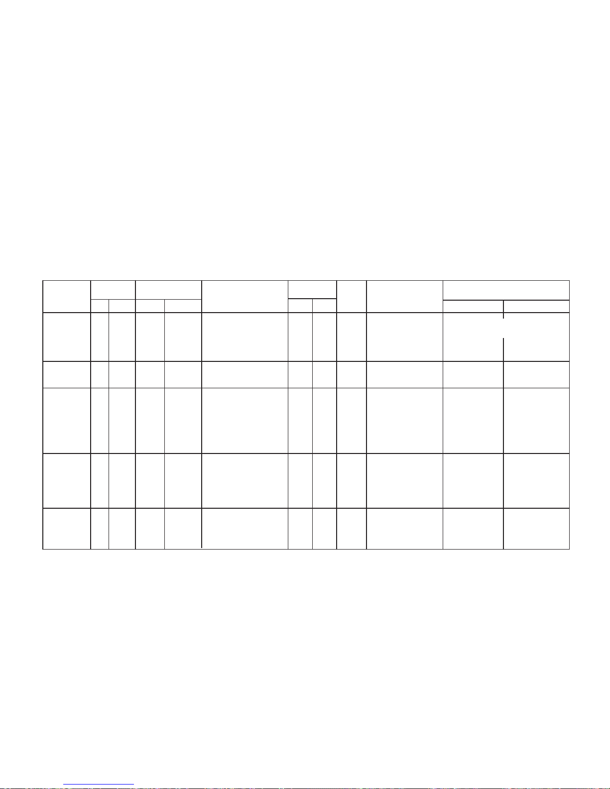
2-1 RS-449/530/MIL INTERFACE PIN CONNECTIONS .................................................................4
2-2 TWINAX CONNECTOR REFERENCES....................................................................................5
3-1 FIREBERD 4000 ANALYSIS RESULTS .................................................................................. 20
3-2 RS-449/530/MIL FIREBERD 4000 DATA INTERFACE
REMOTE CONTROL COMMANDS ......................................................................................23
iv TELECOMMUNICATIONS TECHNIQUES CORPORATION
Page 5

TABLE OF CONTENTS
(Continued)
TABLES PAGE
4-1 FIREBERD 4000 SYNCHRONOUS TEST SET-UP WITH EIA-530 ........................................26
4-2 FIREBERD 4000 SYNCHRONOUS TEST SET-UP WITH RS-449 ......................................... 28
4-3 FIREBERD 4000 SYNCHRONOUS TEST RESULTS ............................................................. 30
4-4 FIREBERD 4000 ASYNCHRONOUS TEST SET-UP WITH 188C ..........................................31
4-5 FIREBERD 4000 ASYNCHRONOUS TEST RESULTS...........................................................32
5-1 FIREBERD 6000 ANALYSIS RESULTS .................................................................................. 40
5-2 RS-449/530/MIL DATA INTERFACE FIREBERD 6000
REMOTE CONTROL COMMANDS ......................................................................................42
6-1 FIREBERD 6000 SYNCHRONOUS TEST SET-UP WITH EIA-530 ........................................44
6-2 FIREBERD 6000 SYNCHRONOUS TEST SET-UP WITH RS-449 ......................................... 46
6-3 FIREBERD 6000 SYNCHRONOUS TEST RESULTS ............................................................. 48
6-4 FIREBERD 6000 ASYNCHRONOUS TEST SET-UP WITH 188C ..........................................49
6-5 FIREBERD 6000 ASYNCHRONOUS TEST RESULTS...........................................................50
7-1 RS-449/530/MIL DATA INTERFACE SPECIFICATIONS ........................................................51
A-1 DATA INTERFACE DEFAULT SETTINGS ..............................................................................55
TELECOMMUNICATIONS TECHNIQUES CORPORATION v
Page 6

vi TELECOMMUNICATIONS TECHNIQUES CORPORATION
Page 7

GENERAL INFORMATION
SECTION 1
1.1 INTRODUCTION
This manual contains descriptions, setup and operating
instructions, specifications, maintenance, and service information for the TTC (Telecommunications Techniques Corporation) Model 41400 RS-449/530/MIL Data Interface.
The RS-449/530/MIL Data Interface allows the FIREBERD
4000 (Rev 3 and above) and FIREBERD 6000 (Revision G
software and above) to be connected to RS-449, MIL-188114, EIA-530, MIL-188C and compatible circuits and to act
as a DTE or DCE device in balanced or unbalanced mode.
1.2 SAFETY CONSIDERATIONS
The following safety considerations should be observed:
• Use a grounding strap when removing or installing
this interface.
• Ensure that power is off when removing or installing
this interface.
• Remove or install the RS-449/530/MIL Data Inter-
face, Model 41400, in a moisture free environment.
• Make sure the RS-449/530/MIL Data Interface, Model
41400, is used with well grounded equipment.
• Always wear safety equipment appropriate for the
job, such as eye protection.
• Never operate the equipment when combustible gases
or fluids are present.
1.3 ENVIRONMENTAL CONSIDERATIONS
The RS-449/530/MIL Data Interface, Model 41400,
should be operated in a non-combustible atmosphere. There
should be no flammable materials in the area. This RS-449/
530/MIL Data Interface, Model 41400, and associated equipment, is sensitive to corrosive materials, including exposure to
salt. This unit is not waterproof.
1.4 INTERFACE FEATURES
The RS-449/530/MIL Data Interface has the following
features.
• Compatible with RS-449, MIL-188-114, EIA-530,
and MIL-188C standards.
• Emulate DTE or DCE.
• Circuit connections using either the 25-pin D-type,
37-pin D-type, or twinax connectors.
• Operates in balanced or unbalanced interface mode.
• User selectable terminating impedance.
• Test in synchronous timing up to 15 Mb/s.
• Test in asynchronous timing up to 20 kb/s.
• Test in recovered timing up to 520 kb/s. (FIREBERD
6000 with clock recovery option.)
• Controlled through the FIREBERD front panel Inter-
face Setup menu or by remote control.
• Control RL and LL lines while emulating DTE and TM
and CTS lines while emulating DCE.
• Select ground termination technique on receive clock
and receive data lines.
• Set the polarity of all interface signaling control leads.
TELECOMMUNICATIONS TECHNIQUES CORPORATION
1
Page 8

1.5 INTERFACE COMPATIBILITY
1.6 OPTIONS AND ACCESSORIES
The RS-449/530/MIL Data Interface is designed in con-
sideration with the following publications and specifications.
• CCITT Recommendation V.10 (or X.26), Electrical
Characteristics of Unbalanced Double-Current Interchange Circuits.
• CCITT Recommendation V.11 (or X.27), Electrical
Characteristics or Balanced Double-Current Interchange Circuits.
• EIA RS-422-A, December 1978, Electrical Charac-
teristics of Unbalanced Voltage Digital Interface
Circuits.
• EIA RS-423-A, December 1978, Electrical Charac-
teristics of Unbalanced Voltage Digital Interface
Circuits.
• EIA RS-449, November 1977, General Purpose
37-Position Interface for DTE and DCE Terminating Equipment.
• EIA-530, 18 March 1987, High Speed 25-Position
Interface for DTE and DCE Terminating Equipment.
• ISO 4902-1980 (E), Data communication -37-pin and
9-pin DTE/DCE Interface Connectors and Pin
Assignments.
The following cables are available from TTC for the
RS-449/530/MIL Interface Adapter.
• Model 10562, 6" RS-449 DTE 37-pin D to X.21 DTE
15-pin.
• Model 10213, 6' RS-232/EIA-530/V.24 male-to-male
connectors.
• Model 10418, 10' RS-232/EIA-530/V.24 male-to-male
connectors.
• Model 10215, 6' RS-449/530/MIL-188 37-pin D,
male-to-male cable.
• Model 10417, 10' RS-449/530/MIL-188 37-pin D,
male-to-male cable.
• Model 10496, 6' MIL-188 male 37-pin D to male
25-pin D cable.
• Model 10538, 6' MIL-188 male 37-pin D to female
25-pin D cable.
• Model 30917, 10' concentric Twinax, 124 ohm.
• MIL-STD-188-114, March 1976, Electrical Charac-
teristics of Digital Interface Circuits Standard.
• MIL-STD-188-100, 15 November 1972, Common
Long Haul and Tactical Communication System Technical Standards.
• MIL-STD-188C, 1969, Military Communications
Technical Standard.
2
TELECOMMUNICATIONS TECHNIQUES CORPORATION
Page 9

INTERFACE DESCRIPTION
SECTION 2
2.1 INTRODUCTION
The RS-449/530/MIL Data Interface is selected and
configured from the FIREBERD mainframe using the
INTERFACE SETUP category or from a computer. The
RS-449/530/MIL Data Interface menu remote control are
discussed in Section 4 for the FIREBERD 4000 and
FIREBERD 6000 Reference Manuals.
This section contains a functional description of each of
the RS-449/530/MIL Data Interface capabilities and features.
2.2 PHYSICAL DESCRIPTION REQUIREMENTS
The RS-449/530/MIL Data Interface has one 37-pin
D-type connector and one 25-pin D-type connector. See
Figure 2-1. Both connectors can be configured as either a
DTE or DCE device through the interface setup menu. The
37-pin D-type connector (RS-449, MIL-188-114) and the
25-pin D-type connector (EIA-530, MIL-188C) provide access to any RS-449, MIL-188-114, EIA-530, or MIL-188C
compatible circuit. The corner pins of each connector are
labeled with the appropriate pin number. See Table 2-1 for
descriptions on the pin outs for each connector.
In addition to the two D-type connectors the interface has
five twinax connectors labeled RCV DATA, RCV CLK, TX
DATA, TX CLK OUT, and EXT TX CLK IN which allow the
FIREBERD to test a wide variety of data handling devices.
See Table 2-2 for twinax connector references.
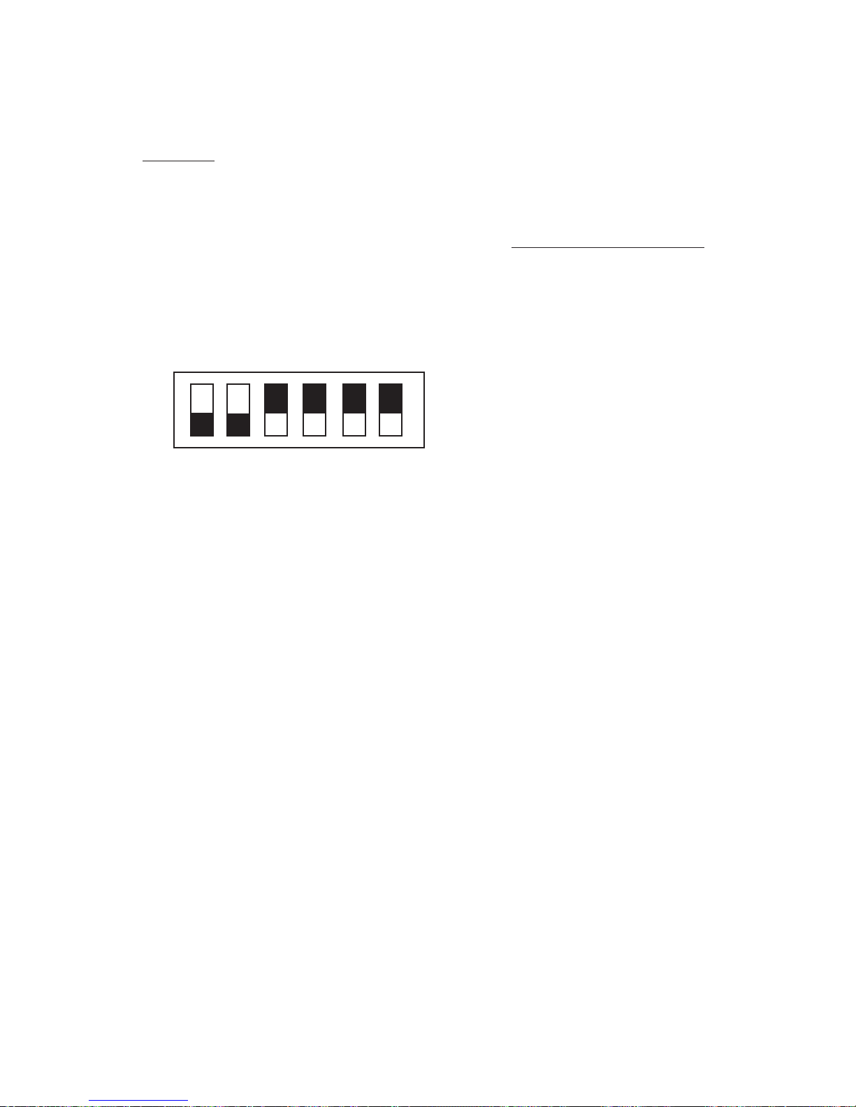
A six-position DIP switch is accessible on the side panel
of the interface. The DIP switch allows for type of
ground termination to be selected for the Receive Clock,
Receive Data, and the external Transmit Clock.
NOTE: The 25-pin D-type, 37-pin D-type, and the twinax
connectors are all wired in parallel. Connect only one
type of connector at a time.
14
1
RS-449/MIL
INTERFACE
ADAPTOR
TELECOMMUNICATIONS TECHNIQUES CORPORATION
RCV DATA RCV CLK TX DATA
EIA-530/MIL-188C
25
20
13
1
RS-449/MIL-188-114
Figure 2-1
The RS-449/530/MIL Data Interface
TX CLK OUT
EXT TX CLK IN
37
19
MODEL 41400
9500384-00
3
Page 10
4
TELECOMMUNICATIONS TECHNIQUES CORPORATION
Table 2-1
RS-449/530/MIL INTERFACE PIN CONNECTIONS
25 Pin
Designations
EIA 530/188C
37 Pin RS449
449/MIL-188-114
Status at Connectors
AB
EIA
CCITT
Description
A
B Circuit
Description
DCE Mode
DTE Mode
1
Shield
—
Shield
1
Shield Shield
Connected to chassis ground
7
AB
102
Signal Ground
19
SG Signal Ground
Connected to chassis ground
37
SC Send Common
Ground
20
RC Receive Common
Ground
214
1
BA
103
Transmitted Data
4
22
1
SD Send Data
Input
Output
316
2
BB
104
Received Data
6
24
2
RD Receive Data
Output
Input
419
1
CA
105
Request to Send
7
25
1
RS Request to Send
Input
Output
513
2
CB
106 Clear to Send
9
27
2
CS Clear to Send
Output
Input
622
2
CC
107 DCE Ready
11
29
2
DM Data Mode
Output
Input
20 23
2
CD
108.2 DTE Ready
12
30
2
TR Terminal Ready
Output
Input
810
2
CF
109 Received Line
13
31
2
RR Receiver Ready
Output
Input
Signal Detector
24 11
1
DA
113 Transmit Signal
17
35
1
TT Terminal Timing
Input
Output
Element Timing (DTE)
15 12
2
DB
114 Transmit Signal
5
23
2
ST Send Timing
Output
Input
Element Timing (DCE)
17 9
1
DD
115 Receiver Signal
8
26
1
RT Receive Timing
Output
Input
18
LL
141 Local Loopback
10
LL Local Loopback
Input
Output
21
RL
140 Remote Loopback
14
RL Remote Loopback
Input
Output
25
TM
142 Test Mode
18
TM Test Mode
Output
Input
Page 11
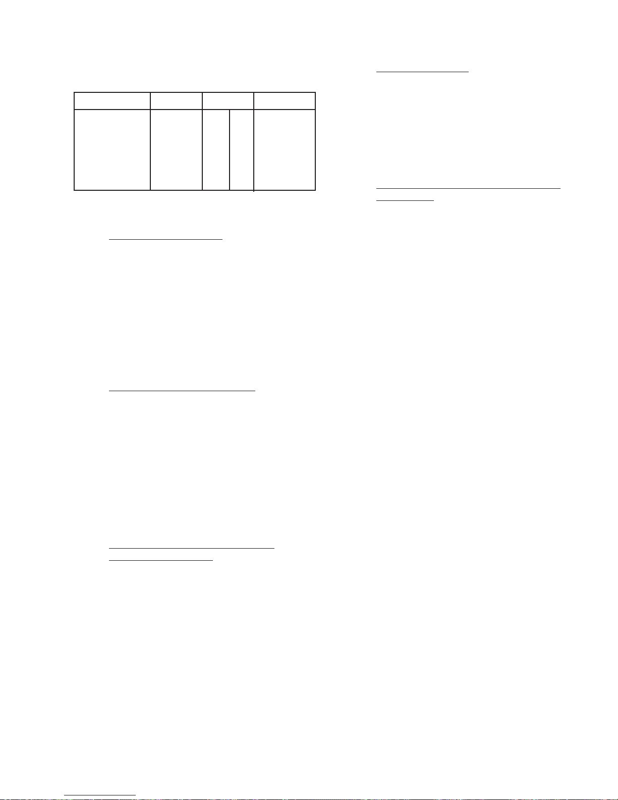
Table 2-2
Twinax Connector References
Circuit Bal Pins Unbal Pins
RCV DATA RD 6 24 6
RCV CLK RT 8 26 8
TX DATA SD 4 22 4
TX CLK OUT TT 17 35 17
EXT CLK IN ST 5 23 5
* Referenced to the RS-449, Recommendation
2.2.1 General Characteristics
The RS-449/530/MIL Data Interface, Model 41400, has
the following dimensions and weight:
Height: 1.5” (38.0 mm)
Width: 7.5” (185.0 mm)
Depth: 5.23” (133.0 mm)
Weight: 13.6 ounces (386 grams)
2.2.4 Equipment Storage
The RS-449/530/MIL Data Interface, Model 41400,
should be stored in the original shipping container when not
in use. Both the FIREBERD and the RS-449/530/MIL Data
Interface, Model 41400, should be stored in a moisture and
vibration free environment.
2.2.5 Unpacking, Assembly, and Installation
Instructions
The package containing the RS-449/530/MIL Data Interface, Model 41400, should be carefully checked for exterior
damage. If no damage is apparent, the package should be
opened carefully so that the RS-449/530/MIL Data Interface,
Model 41400, is not damaged with a cutting blade or other
sharp object. The RS-449/530/MIL Data Interface, Model
41400, should be checked against the bill of materials (BOM)
to make sure that everything matches. Check the RS-449/
530/MIL Data Interface, Model 41400, for any apparent
exterior damage. Report any damage to the carrier and to
TTC. Refer to warranty and return information in Chapter 8
of this manual.
2.2.2 Equipment and Items Included
There is no equipment required to install the RS-449/530/
MIL Data Interface, Model 41400. The RS-449/530/MIL
Data Interface, Model 41400, is simply installed into the
FIREBERD with thumb screws. Refer to paragraph 5.2 for
installation instructions. No other equipment is necessary or
provided. No other items are included with the RS-449/530/
MIL Data Interface, Model 41400, other than this Operating
Manual.
2.2.3 Tools and Equipment Required for
Periodic Maintenance
There are no tools or equipment required for periodic
maintenance. Periodic maintenance consists of cleaning the
RS-449/530/MIL Data Interface, Model 41400’s exterior
with a clean, lint free cloth. Cleaning sprays should not be
used directly on the interface. Contacts should require little or
no periodic maintenance. Contacts may be cleaned with a
clean lint-free cloth. Contacts should not be cleaned with an
abrasive cleaner.
Assembly of the RS-449/530/MIL Data Interface, Model
41400, is not required. The unit comes completely assembled. The interface itself, is the lowest replaceable unit
(LRU). Installation procedures are provided in Section(s) 3
and 5 of this manual.
2.3 FUNCTIONAL DESCRIPTION
The RS-449/530/MIL Data Interface, Model 41400, gives
the FIREBERD 6000 DCE and DTE emulation capabilities.
The RS-449/530/MIL Data Interface, Model 41400, has
25-pin D-type and 37-pin D-type or twinax connectors. In
addition, the RS-449/530/MIL Data Interface, Model 41400,
is capable of operating in either a balanced or unbalanced
mode. Control of the RS-449/530/MIL Data Interface, Model
41400, is via the FIREBERD 6000 front panel interface setup
menu or by remote control. The RS-449/530/MIL Data Interface, Model 41400, is capable of receiving data and clock
inputs from a wide variety of data sources. It also has data and
clock outputs for testing purposes. Internal circuitry consists
of an internal clock generator, pattern generator, and receiver.
This circuitry allows for a wide variety of testing capabilities.
A six-position DIP switch allows for the selection of the
ground termination. Paragraph 2.3.6 contains additional DIP
switch details.
TELECOMMUNICATIONS TECHNIQUES CORPORATION
5
Page 12

The RS-449/530/MIL Data Interface provides the FIREBERD Communications Analyzer with the ability to test and
analyze RS-449, MIL-188-114, EIA-530, and MIL-188C
compatible circuits using either the 25-pin, 37-pin, or twinax
connectors. The following information provides a functional
description of each TYPE of interface operation. For more
information on TYPE selection, see Section 3.
2.3.1 RS-449
When TYPE RS449 is selected, the RS-449/530/MIL
Interface operates in accordance with EIA RS-449, CCITT
V.10 and V.11, and ISO 4902-1980. TYPE RS449 enables a
FIREBERD to act as data terminal equipment (DTE) or data
communications equipment (DCE) when D-type connector is
selected. Connections are made using a 37-pin D-type connector or twinax connector. Operation is possible in balanced
or unbalanced mode. Balanced mode indicates that each
signal is transmitted on two leads in which the voltage is equal
in magnitude and opposite in polarity with respect to a
common reference. This mode is preferred when minimum
noise and cross talk is desired. Unbalanced mode indicates
that each signal is transmitted on one lead with respect to a
common ground. Data transmission is supported in synchronous or asynchronous timing. With asynchronous timing,
asynchronous data analysis can be performed at speeds up to
20 kb/s. With synchronous timing, operation at 15 Mb/s is
possible.
TYPE EIA530 enables a FIREBERD to act as data terminal
equipment (DTE) or data communications equipment (DCE).
Connections are made using a 25-pin D-type connector. Operation is possible in balanced or unbalanced mode. Balanced
mode indicates that each signal is transmitted on two leads in
which the voltage is equal in magnitude and opposite in
polarity with respect to a common reference. This mode is
preferred when minimum noise and cross talk is desired.
Unbalanced mode indicates that each signal is transmitted on
one lead with respect to a common ground. Data transmission
is supported in synchronous or asynchronous timing. With
asynchronous timing, asynchronous data analysis can be performed at speeds up to 20 kb/s. With synchronous timing,
operation at 15 Mb/s is possible.
2.3.4 MIL-188C
When TYPE 188C is selected, the RS-449/530/MIL
Interface operates in accordance with the MIL-STD-188C
Interface specification. This interface enables the
FIREBERD to act as data terminal equipment (DTE) or data
communications equipment (DCE). Connections are made
using a 25-pin D-type connector. Operation is in unbalanced
mode. Unbalanced mode indicates that each signal is transmitted on one lead with respect to a common ground. Data
transmission is supported in synchronous or asynchronous
timing. With asynchronous timing, asynchronous data analysis can be performed at speeds up to 20 kb/s. With synchronous timing, operation at 64 kb/s is possible.
2.3.2 MIL-188-114
When TYPE 188114 is selected, the RS-449/530/MIL
Interface operates in accordance with the MIL-STD-188-114
Bipolar Balanced and Unbalanced Interface Specification,
dated March 1976. TYPE 188114 enables a FIREBERD to act
as data terminal equipment (DTE) or data communications
equipment (DCE). Connections are made using a 37-pin
D-type connector with operation possible in balanced or
unbalanced mode. Balance mode indicates that each signal is
transmitted on two leads in which the voltage is equal in
magnitude and opposite in polarity with respect to a common
reference. This mode is preferred when minimum noise and
cross talk is desired. Unbalanced mode indicates that each
signal is transmitted on one lead with respect to a common
ground. Data transmission is supported in synchronous or
asynchronous timing. With asynchronous timing, asynchronous data analysis can be performed at speeds up to 20 kb/s.
With synchronous timing, operation at 15 Mb/s is possible.
2.3.3 EIA-530
When TYPE EIA530 is selected, the RS-449/530/MIL
Interface operates in accordance with EIA 530 specifications.
2.3.5 Twinax Connectors
The five twinax connectors RCV DATA, RCV CLK,
TX DATA, TX CLK OUT, and EXT TX CLK IN enables the
FIREBERD to test a wide variety of data handling devices.
The connectors enable operation in balanced and unbalanced
mode with the connector shields connected to chassis ground,
the middle conductor carrying the Category II (B) signal, and
the center carrying the Category I (A) signal. Balanced mode
indicates that each signal is transmitted on two leads (A & B)
in which the voltage is equal in magnitude and opposite in
polarity with respect to a common reference. This mode is
preferred when minimum noise and cross talk is desired.
Unbalanced mode indicates that each signal is transmitted on
one lead (A) with respect to a common ground. Data
transmission is supported in synchronous or asynchronous
timing. With asynchronous timing, asynchronous data analysis can be performed at speeds up to 20 kb/s. With synchronous timing, operation at 15 Mb/s is possible. Data generated
by the FIREBERD is transmitted through the TX DATA
jack. The synchronous transmitted clock signal is sent
through the TX CLK OUT jack. Data is returned to the
FIREBERD for analysis through the RCV DATA jack. The
synchronous returned clock is sent through the RCV CLK
6
TELECOMMUNICATIONS TECHNIQUES CORPORATION
Page 13
jack. A clock signal via the EXT TX CLK IN jack may be
selected as the timing source for the transmitted data signal.
2.3.6 DIP Switch
resistors are not terminated to ground allowing line to line
termination. In the opposite (CLOSED) position the
center of the resistors are terminated to ground allowing
line to ground termination.
Use DIP switch position 3, 4, and 5 to reduce the amplitude noise level on the EXT TX CLK IN, RCV CLK, and RCV
DATA leads by changing the line to line termination to line to
ground termination. The 124 ohm line to line termination of
the external transmit clock input, receive clock, and receive
data may be split by placing a 62 ohm resistor from each line
to ground. Figure 2-2 illustrates the factory settings for the
DIP switches.
Open
Closed
1 2 3 4 5 6
9500385-00
Figure 2-2
DIP Switch Factory Settings
Position 1 and Position 2 are not used.
Position 3 External Tx Clock Input -
This switch allows
the center of the two EXT TX CLK IN 62 ohm resistors
to be connected to ground. In the normal (OPEN)
position the two 62 ohm resistors are not terminated to
ground allowing line to line termination. In the opposite
(CLOSED) position the center of the resistors are terminated to ground allowing line to ground termination.
Position 4 Receive Clock - This switch allows the center
of the two RCV CLK 62 ohm resistors to be connected to
ground. In the normal (OPEN) position the two 62 ohm
resistors are not terminated to ground allowing line to line
termination. In the opposite (CLOSED) position the
center of the resistors are terminated to ground allowing
line to ground termination.
Position 5 Receive Data - This switch allows the center
of the two RCV DATA 62 ohm resistors to be connected
to ground. In the normal (OPEN) position the two 62 ohm
2.4 MAINFRAME OPERATION WITH THE
RS-449/530/MIL INTERFACE
2.4.1 Emulating Synchronous DTE
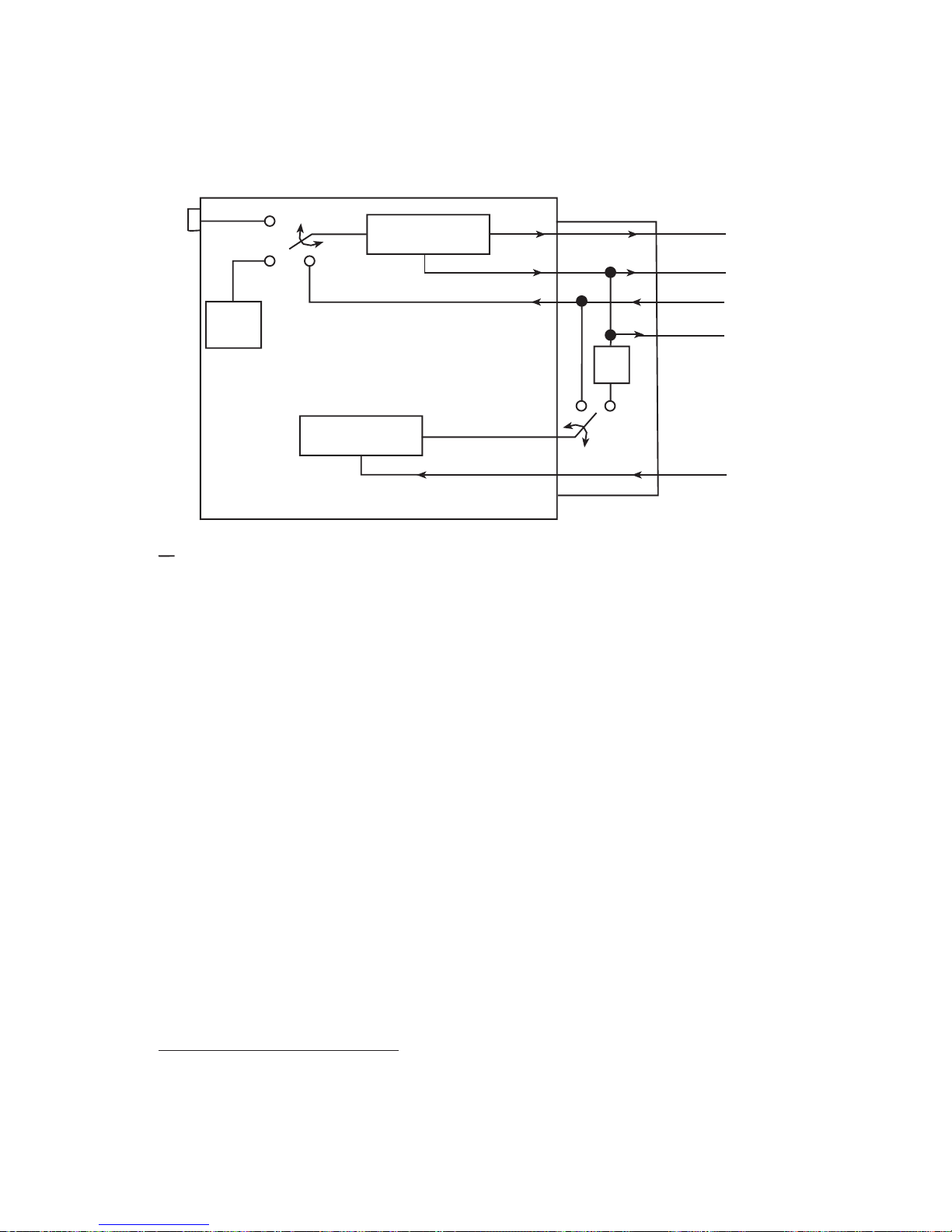
The FIREBERD mainframe generator clock and pattern
selections must be configured for operation with the
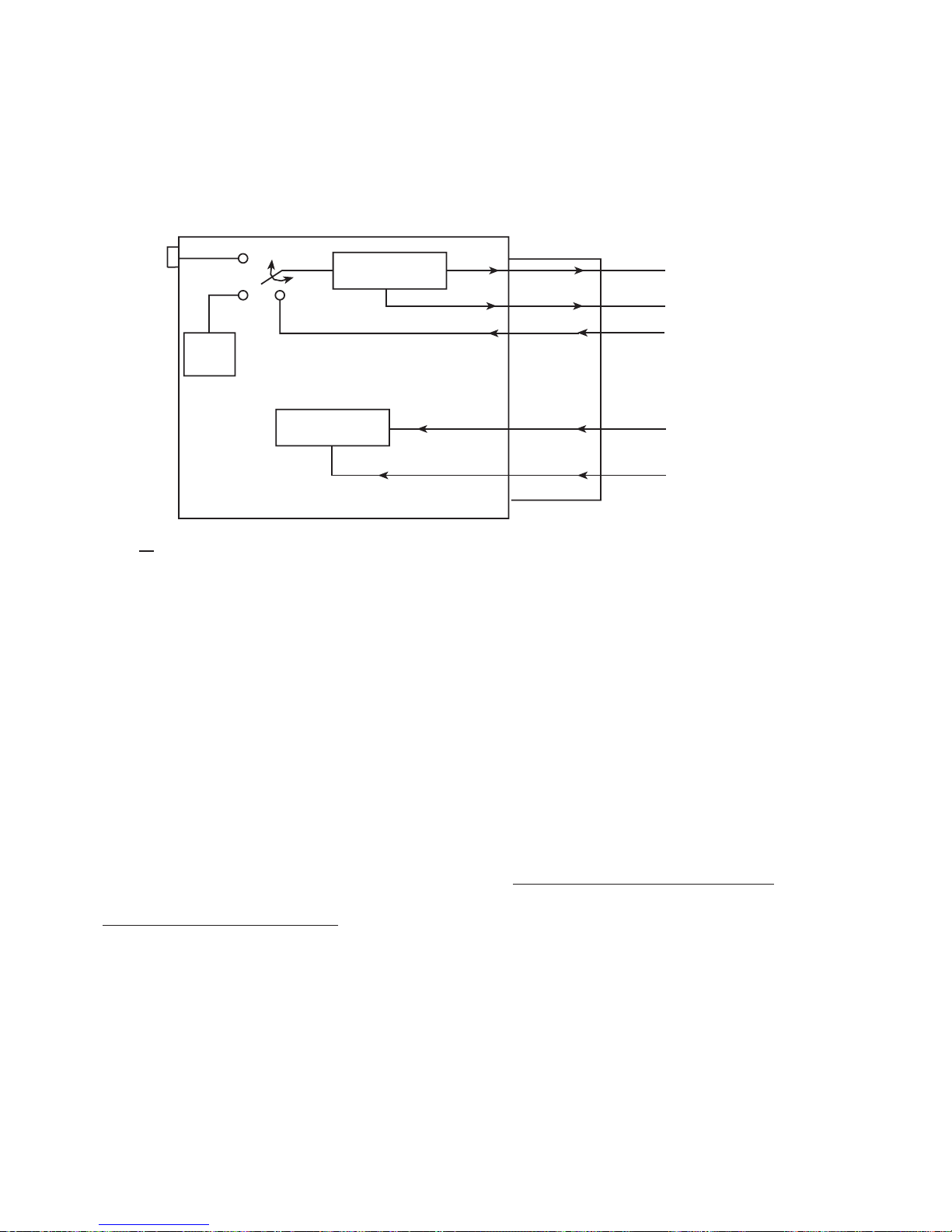
RS-449/530/MIL Interface. Figure 2-3 illustrates a simplified
block diagram of the FIREBERD emulating synchronous
DTE. The diagram shows the relationship between the generator clock, test pattern generator, receiver, and RS-449/530/
MIL Interface transmit and receive data and clock leads. Two
sets of pin numbers are identified: the EIA-530/MIL-188C
connector and the RS-449/MIL 188-114 which is in parenthesis. See Table 2-1 for pin out descriptions.
NOTE: Only Category I circuits are identified. See Table 2-1
for corresponding Category II circuits.
The generator clock selection establishes which clock
source is used during testing: the internal (INTRNL), interface (INTF), or external (BNC). When the generator clock is
set to INTRNL, the mainframe supplies the clock source from
the internal generator clock which is used to generate the test
pattern on Pin 2 Transmitted Data (Pin 4 Send Data) and
supply the external transmit clock on Pin 24 Transmit Clock
DTE source (Pin 17 Terminal Timing DTE source). The DCE
transmit clock on Pin 15 Transmit Clock DCE source (Pin 5
Send Timing DCE source) is ignored when the internal
mainframe clock is used.
With the generator clock set to INTF, the clock on Pin 15
(Pin 5) is used as the transmit timing source for transmitting
the test pattern on Pin 2 (Pin 4). It also supplies the external
transmit clock on Pin 24 (Pin 17). Typically, the DCE supplies
transmit timing to the DTE on Pin 15 (Pin 5) and the DTE
(FIREBERD) generates the data (test pattern) from that clock
and redistributes the timing signal on Pin 24 (Pin 17) to the
DCE. Setting the generator clock for INTF is the recommended selection when the FIREBERD is emulating DTE.
With the generator clock set for BNC, the mainframe is
supplied with the clock source through the GEN CLK IN
connector on the rear panel. The received data is clocked in
on Pin 3 Received Data (Pin 6 Receive Data) with the receive
clock from the DCE on Pin 17 Receive Clock (Pin 8 Receive
Timing) supplying the timing. Signal analysis is performed
on the received data and receive clock signals.
TELECOMMUNICATIONS TECHNIQUES CORPORATION
7
Page 14
GEN CLK IN
BNC
INTRNL
Internal
Gen Clock
FIREBERD
INTF
Pattern
Generator
INTF
CLK
DATA
RS-449/530/MIL
Transmit Data 2
Send Data (4)
Transmit CLK DTE Source 24
Terminal Timing (17)
Transmit CLK DCE Source 15
Send Timing (5)
Receiver
KEY
EIA 530/188C Reference
RS-449/MIL-188-114 Reference
FIREBERD Emulating Synchronous DTE
Set the pattern selection to any test pattern, except FOX
and USER 1-3. If the Long User Option is installed these
patterns may be selected.
During DTE emulation, the Interface Status and Control
panel switches control RTS (Request To Send) and DTR
(Data Terminal Ready) by turning the leads off and on. The
status of RLSD (Received Line Signal Detector), DSR (Data
Set Ready), TM (Test Mode), and CTS (Clear To Send) is
monitored and displayed on the front panel.
CLK
DATA
Receive CLK 17
Receive Timing (8)
Receive DATA 3
Receive DATA (6)
Figure 2-3
During DCE emulation, the Interface Status and Control
panel switches control RLSD (Received Line Signal Detector) and DSR (Data Set Ready) by turning the leads off and on.
The status of RTS (Request to Send), LL (Local Loopback),
RL (Remote Loopback), and DTR (Data Terminal Ready) is
monitored and displayed on the front panel. TM (Test Mode)
and CTS (Clear to Send) are controlled using the Signaling
Menu.
2.4.3 Emulating Asynchronous DTE/DCE
9500386-00
2.4.2 Operating as Synchronous DCE
The FIREBERD mainframe generator clock and pattern
selections must be configured for operation with the RS-449/
530/MIL Interface. Figure 2-4 illustrates a simplified block
diagram of the FIREBERD 4000 emulating synchronous
DCE. The diagram shows the relationship between the
generator clock, test pattern generator, receiver, and RS-449/
530/MIL Interface transmit and receive data and clock leads.
Two sets of pin numbers are identified: the EIA-530/MIL188C connector and the RS-449/MIL 188-114 which is in
parenthesis. See Table 2-1 for pin out descriptions.
8
When selecting asynchronous DTE/DCE operation the
data bits (5, 6, 7, on 8), parity (EVEN, ODD, NONE), and the
stop bits (1, 1.5, or 2) need to match the parameters of the
equipment being tested. The FIREBERD can emulate asynchronous DTE/DCE and operate from 50 kb/s to 20 kb/s. Set
the generator clock to INTERNAL and select the appropriate
clock frequency to match the required data rate. Do not use the
BNC selections when operating asynchronously.
The following patterns are valid in asynchronous testing:
MARK, SPACE, 1:1, 63, 511, 2047, 215-1, FOX, and USER
TELECOMMUNICATIONS TECHNIQUES CORPORATION
Page 15
GEN CLK IN
KEY
EIA 530/188C Reference
RS-449/MIL-188-114 Reference
BNC
INTRNL
Internal
Gen Clock
FIREBERD
RS-449/530/MIL
INTF
Receiver
Pattern
Generator
DATA
CLK
TT
CLK
DATA
Figure 2-4
FIREBERD Emulating Synchronous DCE
Received DATA 3
Received DATA (6)
Receive CLK 17
Receive Timing (8)
Transmit CLK DTE Source 24
Terminal Timing (17)
Transmit CLK DCE Source 15
Send Timing (5)
TT
Delay
ST
Transmitted DATA 2
Send DATA (4)
9500387-00
1-3. If any other pattern is selected, ASYNC PATTERN
CONTENTION flashes in the ANALYSIS RESULTS
display.
During DCE emulation, the Interface Status and Control
panel switches control RLSD (Received Line Signal Detector) and DSR (Data Set Ready) by turning the leads off and on.
RL (Remote Loopback) and LL (Local Loopback) are controlled using the Signaling Menu. The status of RTS (Request
to Send), LL (Local Loopback), RL (Remote Loopback), and
DTR (Data Terminal Ready) is monitored and displayed on
the front panel. During DTE emulation, the Interface status
and Control panel switches control RTS (Request To Send)
and DTR (Data Terminal Ready) by turning the leads off and
on. The status of RLSD (Received Line Signal Detector),
DSR (Data Set Ready), TM (Test Mode), and CTS (Clear To
Send) is monitored and displayed on the front panel.
2.4.4 Operating in the Self-Loop Mode
In DTE emulation, the self-loop mode loops the TD lead
Pin 2 (Pin 4) to the RD lead Pin 3 (Pin 6) and the XTC lead Pin
24 (Pin 17) to the RC lead Pin 17 (Pin 8). Timing can be
provided by the DCE on Pin 15 (Pin 5) [generator clock set to
INTF], the internal generator clock [generator clock set to
INTRNL], or the rear panel GEN CLK IN connection [generator clock set to BNC].
In DCE emulation, the self-loop mode loops the RD lead
Pin 3 (Pin 6) to the TD lead Pin 2 (Pin 4) and the RC lead Pin
17 (Pin 8) to the XTC lead Pin 24 (Pin 17). Timing can be
provided by the internal generator clock (generator clock set
to INTRNL) or the rear panel GEN CLK IN connection
(generator clock set to BNC). User connections do not have
to be disconnected to perform the self-loop test.
TELECOMMUNICATIONS TECHNIQUES CORPORATION
9
Page 16

10
TELECOMMUNICATIONS TECHNIQUES CORPORATION
Page 17
FIREBERD 4000
INSTALLATION AND OPERATION
SECTION 3
3.1 INTRODUCTION
This section describes how to install, configure, and
operate the RS-449/530/MIL Data Interface with a FIREBERD 4000. Refer to the FIREBERD 4000 User’s Guide or
the FIREBERD 4000 Reference Manual for mainframe oper-
ating procedures.
NOTE: Configure the FIREBERD 4000 and the RS-449/530/
MIL Data Interface before connecting the FIREBERD to the circuit under test. This avoids unnecessary circuit downtime.
3.1.1Repair and Replace Procedure
The RS-449/530/MIL Data Interface, Model 41400, is
provided as a self-contained unit. If repairs are necessary, the
entire interface should be replaced. Section 8 of this manual
contains information about the warranty and return policies.
3.2 INSTALLING THE INTERFACE
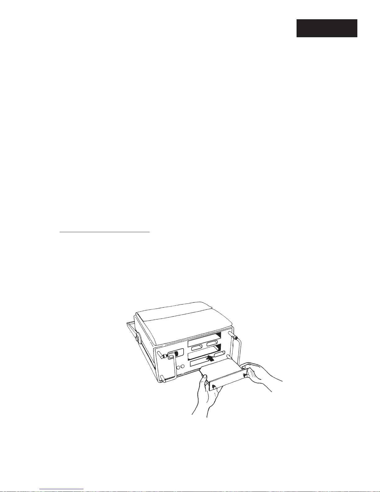
The following procedure describes how to install the
RS-449/530/MIL Interface in the FIREBERD 4000. Figure
3-1 illustrates how the interface is installed.
CAUTION: Before installing or removing the interface mod-
ule, turn the AC power OFF to the FIREBERD
mainframe. Damage can occur to the interface
and mainframe.
1. Power OFF the FIREBERD.
2. Face the FIREBERD rear panel.
NOTE: The FIREBERD 4000 may have two interface
slots. SLOT1 (bottom slot) is the standard
interface slot and SLOT2 (top slot) is the
optional interface slot (Option 4001).
TELECOMMUNICATIONS TECHNIQUES CORPORATION
9500388-00
Figure 3-1
Installing a Modular Interface
11
Page 18

3. Insert the interface into a vacant interface slot.
Verify that the interface faces up.
4. Slide the module into the FIREBERD until the
interface panel is flush with the rear panel. Make
sure the PC board edges are fitted into the card
guides inside the interface slot.
Use the SETUP SELECT switch to step through the menus.
Press the softkeys to select a function as indicated by the
softkey labels on the bottom line of the display. To return to
the interface select menu, press the mainframe HOME key.
All interface menu settings are retained when power is removed from the mainframe. See Figures 3-2 through 3-7 for
the interface menus.
5. Secure the interface with the two thumbscrews on
the interface panel.
3. 2. 1 Performance Verification
The proper performance of the RS-449/530/MIL
Data Interface, Model 41400, is verified by installing the
interface in the FIREBERD 4000 as described in the previous
paragraphs. The FIREBERD 4000 should be setup as described in the step-by-step procedures in the following paragraphs. The equipment should be powered-up and the various
menus and setups performed to ensure proper operation. If
any test fails, be sure to check connections, continuity of
cables, and proper seating of the interface into the FIREBERD.
An analysis of test results and proper performance indicators
are provided in the analysis results section at the back of this
section. In addition, the FIREBERD 4000 Reference Manual
provides additional performance verification and validation
results.
3.2.2 Calibration Procedures
The RS-449/530/MIL Data Interface, Model 41400, is
factory checked and requires no calibration. The FIREBERD
4000 is calibrated as described in the FIREBERD 4000
Reference Manual.
3.2.3 Parts List and Vendors List
No parts list or vendors list is provided because the
RS-449/530/MIL Data Interface, Model 41400, is the LRU.
See Section 8 of this manual for replacement and warranty
information.
3.3.1 Operating Type Menu
The Operating Type (TYPE) menu allows the user to
select either 188114, RS449, EIA530, or 188C as the type of
interface operation. Press the appropriate softkey to select the
desired operating type. Press the MORE key to display the
188C softkey label. Modifying TYPE will cause a test restart.
188114 - The 188114 operating type configures the
interface to be connected to a MIL-188-114 compatible
circuit.
RS449 - The RS449 operating type configures the inter-
face to be connected to a RS-449 compatible circuit.
EIA530 - The EIA530 operating type configures the
interface to be connected to a EIA-530 compatible cir-
cuit.
188C - The 188C operating type configures the interface
to be connected to a MIL-188C compatible circuit.
3.3.2 Connector Menu
The connector (CONNECTOR) menu only appears when
TYPE 188114 or TYPE RS449 is selected. This menu
controls the type of data interface which the FIREBERD can
be connected to. Modifying CONNECTOR will causes a test
restart. Pressing the associated softkey selects either D-TYPE
or TWINAX.
D-TYPE - When the D-TYPE softkey is pressed, the
interface is configured to use the RS-449/MIL188-114,
37-pin connector.
3.3 FIREBERD 4000 INTERFACE SET-UP
This section describes how to access the interface menu
and discusses each of the menu selections in the RS-449/530/
MIL Data Interface menu.
The RS-449/530/MIL Data Interface is controlled through
the FIREBERD 4000 INTERFACE SETUP category. Press
the MIL449 softkey to access the MIL449 interface menu.
12
TWINAX - When the TWINAX softkey is pressed, the
interface is configured to use the twinax connectors.
3.3.3 Emulate Menu
The Emulate (EMULATE) menu establishes the interface emulation mode. Pressing the associated softkey selects
either DTE or DCE emulation. This menu does not appear
when the selected CONNECTOR is TWINAX.
TELECOMMUNICATIONS TECHNIQUES CORPORATION
Page 19
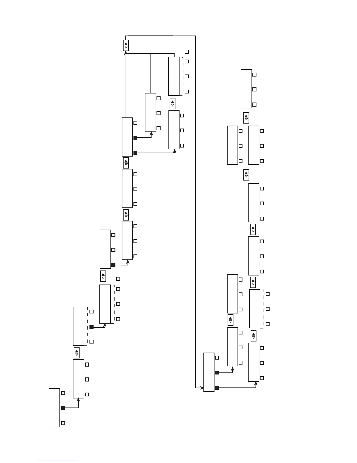
Figure 3-2
FIREBERD 4000 RS-449/530/MIL Data Interface Setup Menu
MORE
Type RS-449 D-Type
IMPEDANCE: XXXXXX
78 100 124
UNTERM
SIGNALING: ON=XXX
POS NEG
MODE: UNBAL
BAL UNBAL
MODE: BAL
BAL UNBAL
MODE: XXXXXX
BAL UNBAL
EMULATE: XXXXXX
DTE DCE
★
TM:XXX CTS:XXX
LL:XXX RL:XXX
★★
TM CTS
LL RL
9500389-00
CONNECTOR: XXXXX
D-TYPE TWINAX
TYPE: RS449
188114 RS449 EIA530
TYPE: XXXXXX
188114 RS449 EIA530
INTERFACE: MIL449
INT232 MIL449 INT188
MORE
188C
CONNECTOR: D-TYPE
D-TYPE TWINAX
★
RCV CLOCK: XXXXXX
TT ST
TIMING: SYNC
ASYNC SYNC
TIMING: XXXXXX
ASYNC SYNC
STOP BITS: XXXXXX
1 1.5 2
PARITY: XXXXXX
EVEN ODD NONE
DATA BITS: XXXXXX
5 6 7
8
TIMING: ASYNC
ASYNC SYNC
EMULATE DCE
EMULATE DTE
★
★★
Figure 3-2
Type RS-449 D-Type
FIREBERD 4000 RS-449/530/MIL Data Interface Setup Menu
INTERFACE: XXXXXX
INT232 MIL449 INT188
TELECOMMUNICATIONS TECHNIQUES CORPORATION
13
Page 20
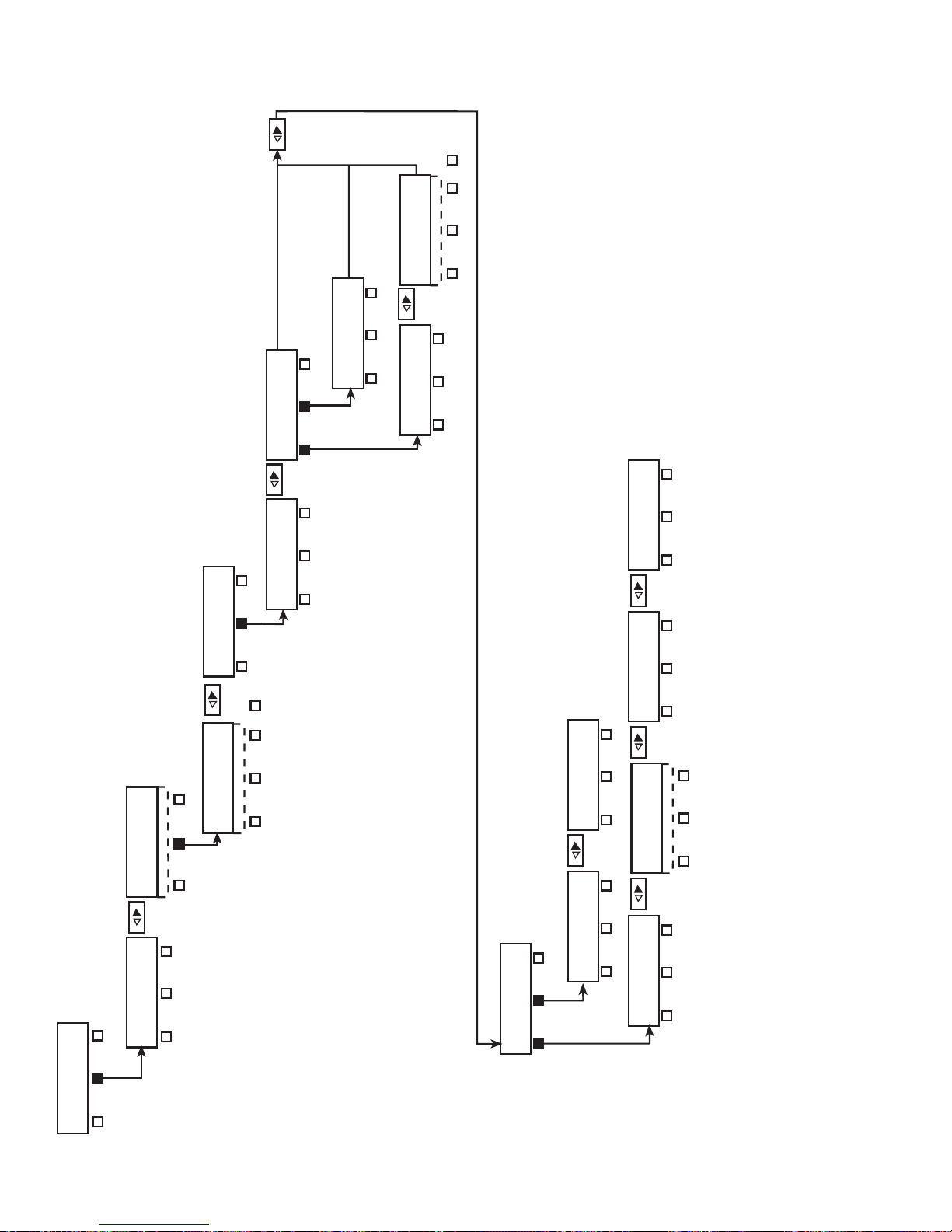
Figure 3-3
FIREBERD 4000 RS-449/530/MIL Data Interface
Setup Menu
Type RS-449 Twinax
Figure 3-4
FIREBERD 4000 RS-449/530/MIL Data Interface
Setup Menu
Type 188/114 D-Type
Figure 3-5
FIREBERD 4000 RS-449/530/MIL Data Interface
Setup Menu
Type 188/114 Twinax
MODE: UNBAL
Figure 3-6
BAL UNBAL
FIREBERD 4000 RS-449/530/MIL Data Interface
Setup Menu
Type 188C
MODE: XXXXXX
BAL UNBAL
Figure 3-7
FIREBERD 4000 RS-449/530/MIL Data Interface
Setup Menu
Type EIA530
MORE
IMPEDANCE: XXXXXX
78 100 124
UNTERM
MODE: BAL
BAL UNBAL
STOP BITS: XXXXXX
1 1.5 2
9500390-00
CONNECTOR: XXXXXX
D-TYPE TWINAX
TYPE: RS449
188114 RS449 EIA530
TYPE: XXXXXX
188114 RS449 EIA530
188C
INTERFACE: MIL449
INT232 MIL449 INT188
MORE
188C
CONNECTOR: TWINAX
D-TYPE TWINAX
★
RCV CLOCK: XXXXXX
TT ST
TIMING: SYNC
ASYNC SYNC
TIMING: XXXXXX
ASYNC SYNC
PARITY: XXXXXX
EVEN ODD NONE
DATA BITS: XXXXXX
5 6 7
8
TIMING: ASYNC
ASYNC SYNC
Figure 3-3
Type RS-449 Twinax
FIREBERD 4000 RS-449/530/MIL Data Interface Setup Menu
EMULATE DCE
★
INTERFACE: XXXXXX
INT232 MIL449 INT188
14
TELECOMMUNICATIONS TECHNIQUES CORPORATION
Page 21
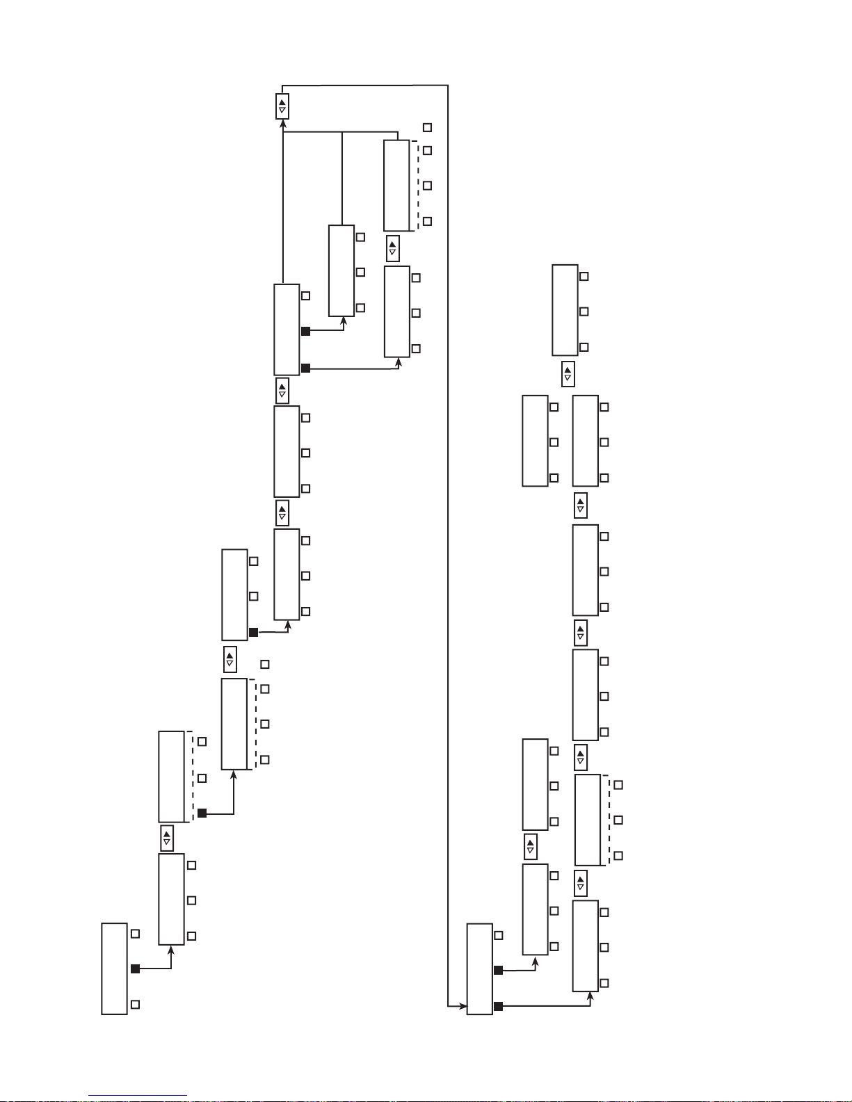
9500391-00
★ EMULATE DCE
★★ EMULATE DTE
INTERFACE: XXXXXX
INT232 MIL449 INT188
INTERFACE: MIL449
INT232 MIL449
TYPE: XXXXXX
188114 RS449 EIA530
188C
MORE
TYPE: 188114
188114 RS449 EIA530
188C
CONNECTOR: XXXXXX
D-TYPE TWINAX
CONNECTOR: D-TYPE
D-TYPE TWINAX
MODE: UNBAL
BAL UNBAL
MODE: BAL
BAL UNBAL
IMPEDANCE: XXXXXX
78 100 124
UNTERM
MORE
TIMING: XXXXXX
ASYNC SYNC
TIMING: SYNC
ASYNC SYNC
RCV CLOCK: XXXXXX
TT ST
★
TIMING: ASYNC
ASYNC SYNC
DATA BITS: XXXXXX
5 6 7
8
PARITY: XXXXXX
EVEN ODD NONE
STOP BITS: XXXXXX
1 1.5 2
EMULATE: XXXXXX
DTE DCE
MODE: XXXXXX
BAL UNBAL
LL:XXX RL:XXX
LL RL
TM:XXX CTS:XXX
TM CTS
SIGNALING ON=XXX
POS NEG
★
★★
Figure 3-4
Type 188/114 D-Type
FIREBERD 4000 RS-449/530/MIL Data Interface Setup Menu
TELECOMMUNICATIONS TECHNIQUES CORPORATION
15
Page 22
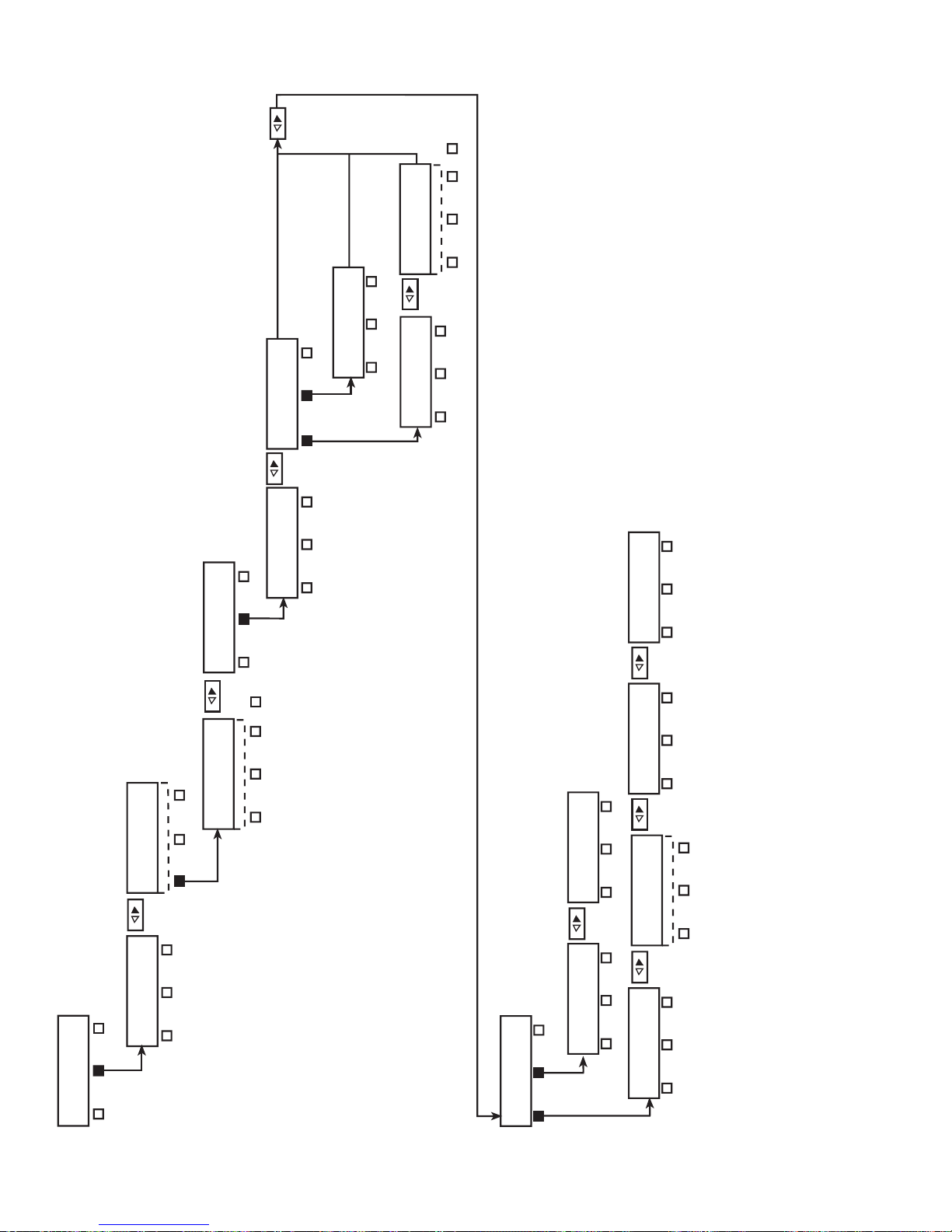
9500392-00
★
EMULATE DCE
INTERFACE: XXXXXX
INT232 MIL449 INT188
INTERFACE: MIL449
INT232 MIL449 INT188
TYPE: XXXXXX
188114 RS449 EIA530
188C
MORE
TYPE: 188114
188114 RS449 EIA530
188C
CONNECTOR: XXXXX
D-TYPE TWINAX
CONNECTOR: TWINAX
D-TYPE TWINAX
MODE: XXXXXX
BAL UNBAL
MODE: UNBAL
BAL UNBAL
MODE: BAL
BAL UNBAL
IMPEDANCE: XXXXXX
78 100 124
UNTERM
MORE
TIMING: XXXXXX
ASYNC SYNC
TIMING: SYNC
ASYNC SYNC
RCV CLOCK: XXXXXX
TT ST
★
TIMING: ASYNC
ASYNC SYNC
DATA BITS: XXXXXX
5 6 7
8
PARITY: XXXXXX
EVEN ODD NONE
STOP BITS: XXXXXX
1 1.5 2
Figure 3-5
Type 188/114 Twinax
16
TELECOMMUNICATIONS TECHNIQUES CORPORATION
FIREBERD 4000 RS-449/530/MIL Data Interface Setup Menu
Page 23
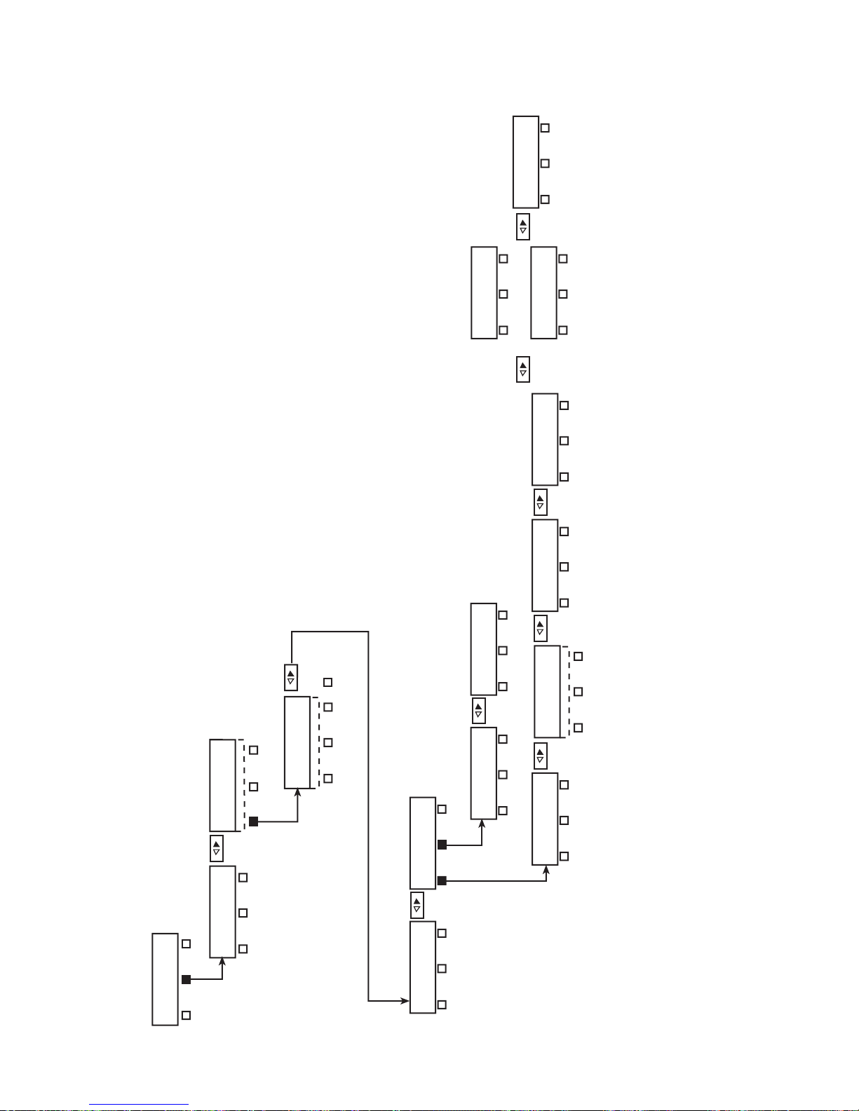
9500393-00
★
EMULATE DCE
★★
EMULATE DTE
INTERFACE: XXXXXX
INT232 MIL449 INT188
INTERFACE: MIL449
INT232 MIL449 INT188
TYPE: XXXXXX
188114 RS449 EIA530
188C
MORE
TYPE: 188C
188114 RS449 EIA530
188C
EMULATE: XXXXXXX
DTE DCE
TM:XXX CTS:XXX
TM CTS
SIGNALING: ON=XXX
POS NEG
★
TIMING: ASYNC
ASYNC SYNC
DATA BITS: XXXXXX
5 6 7
8
PARITY: XXXXXX
EVEN ODD NONE
STOP BITS: XXXXXX
1 1.5 2
TIMING: XXXXXX
ASYNC SYNC
TIMING: SYNC
ASYNC SYNC
RCV CLOCK: XXXXXX
TT ST
LL:XXX RL:XXX
LL RL
★★
★
Figure 3-6
Type 188C
FIREBERD 4000 RS-449/530/MIL Data Interface Setup Menu
TELECOMMUNICATIONS TECHNIQUES CORPORATION
17
Page 24
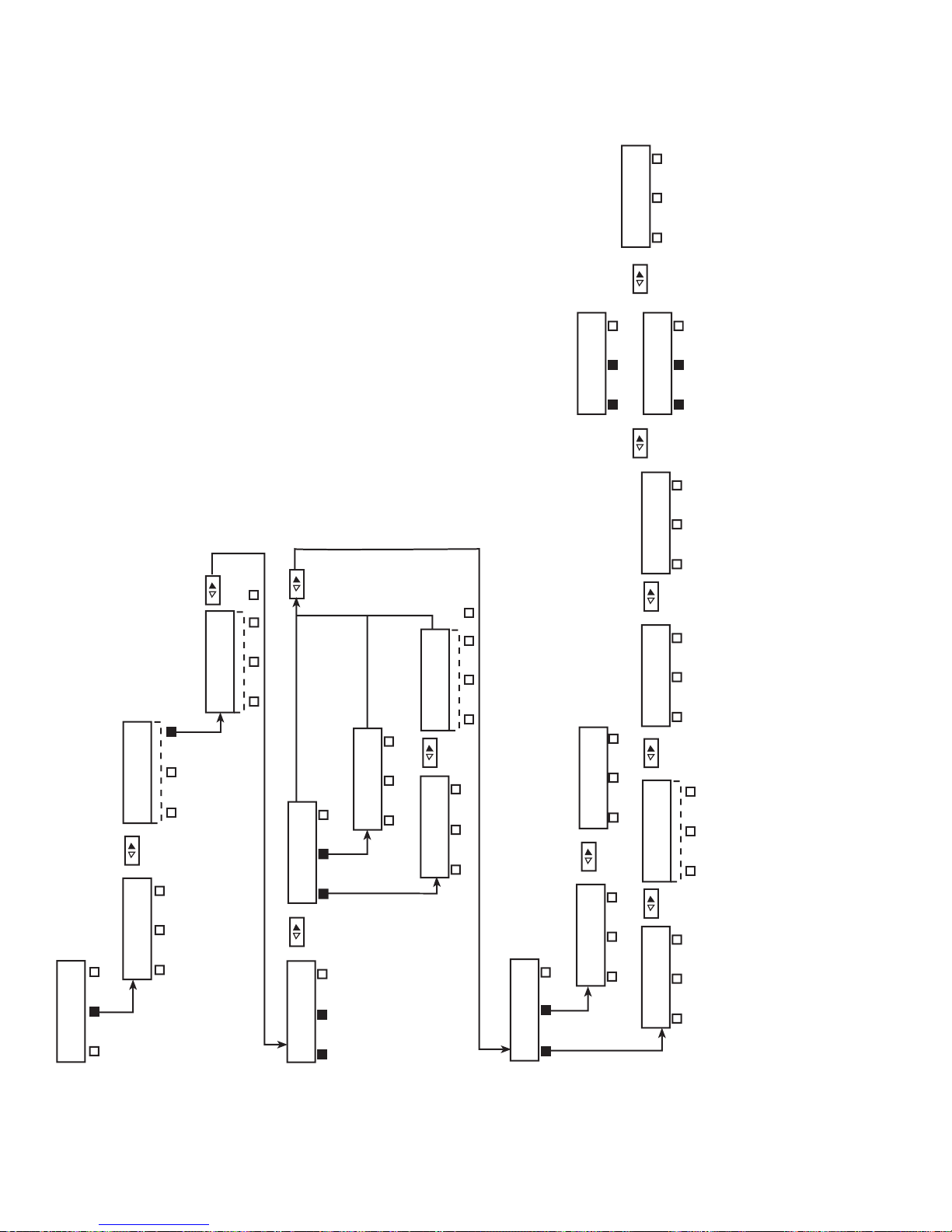
9500394-00
★
EMULATE DCE
★★ EMULATE DTE
INTERFACE: XXXXXX
INT232 MIL449 INT188
INTERFACE: MIL449
INT232 MIL449 INT188
TYPE: XXXXXX
188114 RS449 EIA530
188C
MORE
TYPE: EIA-530
188114 RS449 EIA530
188C
EMULATE: XXXXXXX
DTE DCE
MODE: XXXXXX
BAL UNBAL
TM:XXX CTS:XXX
TM CTS
★
TIMING: SYNC
ASYNC SYNC
RCV CLOCK: XXXXXX
TT ST
DATA BITS: XXXXXX
5 6 7
8
PARITY: XXXXXX
EVEN ODD NONE
TIMING: XXXXXX
ASYNC SYNC
MODE: UNBAL
BAL UNBAL
LL:XXX RL:XXX
LL RL
IMPEDANCE: XXXXXX
78 100 124
UNTERM
SIGNALING: ON=XXX
POS NEG
MODE: UNBAL
BAL UNBAL
MORE
TIMING: ASYNC
ASYNC SYNC
STOP BITS: XXXXXX
1 1.5 2
★
★★
Figure 3-7
Type EIA530
FIREBERD 4000 RS-449/530/MIL Data Interface Setup Menu
18
TELECOMMUNICATIONS TECHNIQUES CORPORATION
Page 25

DTE - This selection allows the FIREBERD mainframe
to emulate DTE.
to select the 8-bit format (default = 8). Modifying DATA
BITS will cause a test restart.
DCE - This selection allows the FIREBERD mainframe
to emulate DCE.
3.3.4 Mode Menu
The Mode (MODE) menu allows the user to select
between balanced and unbalanced operation. Modifying
MODE causes a test restart.
BAL - This selection allows the FIREBERD to operate in
a balanced mode. Balanced mode indicates that each
signal is transmitted on two leads in which the voltage is
equal in magnitude and opposite in polarity with respect
to a common reference. This mode is preferred when
minimum noise and cross talk is desired. When balanced
mode is selected the following menu is provided to set the
termination impedance. The termination impedance
should be set to match the characteristics of the cable.
IMPEDANCE -
This menu allows you to select either a
termination impedance of 78 ohms, 100 ohms, 124
ohms, or UNTERM (>7.4 k ohms).
UNBAL - This selection allows the FIREBERD to operate
in an unbalanced mode. In unbalanced mode each signal
is transmitted on one lead with respect to a common
ground.
3.3.5 Timing Menu
PARITY: EVEN|ODD|NONE - This menu determines the
orientation of the parity bit. Parity is a form of error
detection used in asynchronous data. Press the associated
softkey to select the appropriate parity: EVEN, ODD, or
NONE. Selecting EVEN enables the parity bit when the
number of ones in the data byte is an even number.
Selecting ODD enables the parity bit when the number of
ones in the data byte is an odd number. Select NONE
when no parity bit is used (default = ODD). Modifying
PARITY will cause a test restart.
STOP BITS: 1|1.5|2 - This menu determines the number
of stop bits required in the character format. Press the
associated softkey to select the appropriate stop bit format: 1, 1.5, or 2 (default = 1). Modifying STOP BITS will
cause a test restart.
SYNC - This selects the synchronous timing mode. With
synchronous timing, operation to 15 Mb/s is possible
(default = SYNC).
RCV CLOCK - This menu only appears when the main-
frame is emulating synchronous DCE using a D-Type
connector. This menu selects the timing reference that
the mainframe is synchronized to: TT (Terminal Timing), or ST (Send Timing). When TT is selected, the
receiver timing source comes from Pin 24 (EIA530/
MIL188C) or Pin 17 (RS-449/MIL188-114) . When ST
is selected, the receiver timing source is the mainframe
generator clock that is sent out on Pin 15 (EIA530/
MIL188C) or Pin 5 (RS-449/MIL188-114).
The Timing (TIMING) menu establishes the mainframe
timing mode. Pressing the associated softkey selects either
asynchronous (ASYNC) or synchronous (SYNC) timing.
Modifying TIMING will cause a test restart.
ASYNC - This softkey selects the asynchronous timing
mode. Asynchronous timing is limited to data rates up to
20 kb/s. The following PATTERNs are valid in asynchronous testing: MARK, SPACE, 1:1, 63, 511, 2047,
215-1, FOX, and USER 1-3. When using asynchronous
timing, the following menus are provided to set the
character length, parity, and stop bits. The selected
parameters should be consistent with the parameters of
the equipment being tested.
DATA BITS: 5|6|7|8 - This menu determines the number
of bits used to create the data byte format. The bit length
can be 5, 6, 7, or 8 bits long. Press the associated softkey
to select the appropriate bit length. Press the MORE key
TELECOMMUNICATIONS TECHNIQUES CORPORATION
3.3.6 Signaling Menu
TM:OFF|ON CTS:OFF|ON - This menu only appears
when the mainframe is configured for D-TYPE CONNECTOR and DCE EMULATION. The operation of the
TM (Test Mode) lead [Pin 25 (EIA530/MIL188C) or Pin
18 (RS-449/MIL188-114)] and the operation of the CTS
(Clear to Send) lead [Pin 5 (EIA530/MIL188C) or Pin 9
(RS-449/MIL188-114)] are controlled by this menu. Press
the TM softkey to toggle the TM lead ON and OFF. ON
equals a logic HIGH. OFF equals a logic LOW. Press the
CTS softkey to toggle the CTS lead ON and OFF. ON
equals a logic HIGH. OFF equals a logic LOW.
LL:OFF|ON RL:OFF|ON - This menu only appears when
the mainframe is configured for D-TYPE CONNECTOR
and DTE EMULATION. The operation of the LL (Local
Loopback) lead [Pin 18 (EIA530/MIL188C) or Pin 10
19
Page 26
(RS-449/MIL188-114)] and the operation of the RL
(Remote Loopback) lead [Pin 21 (EIA530/MIL188C) or
Pin 18 (RS-449/MIL188-114)] are controlled by this
menu. Press the LL softkey to toggle the LL lead ON and
OFF. ON equals a logic HIGH. OFF equals a logic LOW.
Press the RL softkey to toggle the RL lead ON and OFF.
ON equals a logic HIGH. OFF equals a logic LOW.
POS (positive) or NEG (negative) polarity. Selecting
ON=POS sets the ON condition to a positive value and an
OFF condition to a negative value. Selecting ON=NEG
sets the ON condition to a negative value and an OFF
condition to a positive value.
SIGNALING:ON=POS|NEG - This menu only appears
when the D-TYPE CONNECTOR is selected. This menu
controls the polarity of all the interface signaling control
leads. Press the appropriate softkey to set ON equal to
Table 3-1
FIREBERD 4000 Analysis Results
Category Displayed Result Description
ERROR AVG BER Average Bit Error Rate
AVG BLER Average Block Error Rate
BER Bit Error Rate
BIT ERRS Bit Errors
BLK ERRS Block Errors
BLOCKS Blocks
CHAR ERR
1
PAT LOSS Pattern Synchronization Loss
PAT SLIP
2
TIME & SIGNAL %EFS Percent of Error-Free Seconds
DATE Date
DELAY
4
ELAP SEC Elapsed Seconds
ERR SEC Errored Seconds
GEN FREQ Generator Clock Frequency
PATL SEC Pattern Loss Seconds
RCV FREQ
3
TEST SEC Test Seconds
TIME Time
3.4 FIREBERD 4000 ANALYSIS RESULTS
Table 3-1 lists the analysis results that are displayed when
the RS-449/530/MIL Data Interface is installed in the FIREBERD 4000. Refer to the FIREBERD 4000 Reference
Manual for results definitions.
Character Errors
Pattern Slips
RTS/CTS Delay
Receiver Clock Frequency
PERFORMANCE
1
Asynchronization timing only
2
Synchronous timing with pseudorandom patterns only
3
Synchronous timing only
5
20
%AVL SEC Percent of Available Seconds
%DEG MIN Percent of Degraded Minutes
%SES Percent of Severely Errored Seconds
AVL SEC Available Seconds
DEG MIN Degraded Minutes
G %EFS G.821 Percent of Error Free Seconds
G EFS G. 821 error Free Seconds
GERR SEC G.821 Errored Seconds
SES Severely Errored Seconds
UNA SEC Unavailable Seconds
4
DTE only
5
Requires option 4004
TELECOMMUNICATIONS TECHNIQUES CORPORATION
Page 27

3.5 FIREBERD 4000 SELF-LOOP TEST
Indicators
The RS-449/530/MIL Data Interface includes a relay that
is activated by the SELF LOOP pushbutton switch on the
FIREBERD front panel. Pressing the SELF LOOP pushbutton
connects the transmit clock and data to the receive clock and
data. This provides quick verification of the FIREBERD and
the data interface. User connections do not need to be
removed during the test, since complete isolation is provided
by the relay when testing in the Self-Loop mode.
3.6 INTERFACE STATUS INDICATORS
AND SWITCHES
Depending on the EMULATE selection (DTE or DCE)
the corresponding front panel interface status and control
panel label will illuminate. The LEDs to the right of these
labels indicate activity on the associated interface connector
lines. The following describes what each LED indicates. The
DTE and DCE emulation labels not in parentheses indicate
EIA 530/MIL-188C lead notation and the labels in parentheses indicate RS-449/MIL188-114 lead notation.
Switches
RLSD (RR) - In DCE emulation the pushbutton switch
controls the state of the Received Line Signal Detector
line. Pressing the RLDS pushbutton causes it to illumi-
nate, forcing this line ON. When the pushbutton LED is
extinguished, the line is held OFF.
RLSD - In DTE emulation, the Received Line Signal
Detector illuminates when this line is ON.
DSR - In DTE emulation, the Data Set Ready LED
illuminates when this line is ON.
CTS - In DTE emulation, the Clear To Send LED illumi-
nates when this line is ON. In DCE emulation, there is no
corresponding LED.
RTS - In DCE emulation, the Request To Send LED
illuminates when this line is ON.
DTR - In DCE emulation, the LED illuminates when this
line is ON.
TM - In DTE emulation, the Test Mode LED illuminates
when this line is ON. In DCE emulation, there is no
corresponding LED.
LL - In DCE emulation, the Local Loopback LED illumi-
nates when this line is ON. In DTE emulation, there is no
corresponding LED.
RL - In DCE emulation, the Remote Loopback LED
illuminates when this line is ON. In DTE emulation, there
is no corresponding LED.
3.7 FIREBERD 4000 PRINTER OPERATION
DSR (DM) - In DCE emulation, pressing the correspond-
ing pushbutton illuminates the LED and forces the DSR
line ON. Pressing this pushbutton again extinguishes the
LED and the DSR line is held OFF.
RTS - In DTE emulation, pressing the Request To Send
pushbutton illuminates the LED and forces this line ON.
Pressing this pushbutton again extinguishes the LED and
holds the line OFF.
DTR - In DTE emulation, pressing this pushbutton illumi-
nates the LED and forces the Data Terminal Ready line
ON.
Refer to the FIREBERD 4000 Reference Manual for
printer setup and operating instructions. Figure 3-8 is a typical
Controls printout showing a RS-449/530/MIL Data Interface.
Figure 3-9 shows a typical Results printout with the RS-449/
530/MIL Data Interface.
NOTE: Only the interface setting relevant to the current
interface mode are displayed.
TELECOMMUNICATIONS TECHNIQUES CORPORATION
21
Page 28

CONTROLS PRINT 14:27:19 24 JUL 90
PATTERN QRSS ERROR INSERT OFF
SELF LOOP OFF GEN CLOCK SYNTH
SYN FRQ 1544.0 kHz DISPLAY HOLD OFF
SETUP PROGRAM NO.0
AUXILIARY SETUP
FLOW TR/DTR OFF FLOW DM/DSR OFF
FLOW RS/RTS OFF FLOW CS/CTS OFF
FLOW RRS/RLSD OFF SYN LOS ACT HALT
SYN LOS THR NORMAL USER SYN THR 10
BLOCK LENGTH PATT PRINT FMT STANDARD
STATUS PRINTS OFF PRINT EVENT AUX ER
BIT ERROR OFF BLOCK ERROR OFF
BPV ERROR OFF CODE ERROR OFF
FRAME ERROR OFF FRA WORD ERR OFF
CRC ERROR OFF PATTERN SLIP OFF
INTERFACE SLOT 2 RS449/530/MIL
TYPE RS449 CONNECTOR D-TYPE
EMULATE DTE MODE BAL
IMPEDANCE 100 TIMING ASYNC
LL OFF RL OFF
DTR ON RTS ON
SIG POLAR POSITIVE
Figure 3-8
Controls Printout
MANUAL PRINT 14:29:26 24 JUL 90
BIT ERRS AVG BER
BER PAT SLIP
BLK ERRS BLOCKS
AVG BLER PAT LOSS
PATL SEC ERR SEC
%EFS TEST SEC 1
ELAP SEC 129 GEN FREQ 1543488
RCV FREQ 0.0 DELAY
AVL SEC UNA SEC
%AVL SEC DEG MIN
%DEG MIN G EFS
GERR SEC G %EFS
SES %SES
RR OFF DM OFF
CS OFF TM OFF
RS ON TR ON
IF RS449/530/MIL
Figure 3-9
Long Results Printout
22
TELECOMMUNICATIONS TECHNIQUES CORPORATION
Page 29

3.8 FIREBERD 4000 REMOTE
CONTROL COMMANDS
3-2. The spacing used on each command line must be used as
indicated. Table 3-2 defines the remote control commands
abbreviations. For detailed instructions on remotely control-
The FIREBERD 4000 remote control commands enable
remote control over the RS-449/530/MIL Data Interface. The
ling the FIREBERD 4000, refer to the FIREBERD 4000
Reference Manual.
RS-449/530/MIL Data Interface commands are listed in Table
Table 3-2
RS-449/530/MIL Data Interface FIREBERD 4000 Remote Control Commands
Remote Command Result
INT SET MIL449 TYP Prints current interface type setup
INT SET MIL449 TYP (xxxxxx) Selects the interface type (xxxxxx = 188114, RS449, EIA530, or 188C)
INT SET MIL449 CON Prints current connector setting
INT SET MIL449 CON (xxx) Selects the connector type (xxx = DTY [D-type] or TWI [twinax])
INT SET MIL449 EMU Prints current emulation setup
INT SET MIL449 EMU (xxx) Selects the type of emulation (xxx = DTE or DCE)
INT SET MIL449 MOD Prints current mode setting
INT SET MIL449 MOD (xxx) Selects the mode setting (xxx = BAL or UNBAL)
INT SET MIL449 IMP Prints the current termination impedance
INT SET MIL449 IMP (xxx) Selects the termination impedance (xxx = 78, 100, 124, or UNTERM)
INT SET MIL449 TIM Prints the current timing
INT SET MIL449 TIM (xxx) Selects the timing (xxx = ASY or SYN)
INT SET MIL449 RCV (xx) Selects the receive clock source (xx = TT or ST)
INT SET MIL449 DAT Prints the current data bits setting
INT SET MIL449 DAT (x) Selects the data bits (x = 5, 6, 7, or 8)
INT SET MIL449 PAR Prints the current parity setting
INT SET MIL449 PAR (xxx) Selects the parity (xxx = NON, EVE, or ODD)
INT SET MIL449 STO Prints the current stop bit setting
INT SET MIL449 STO (xxx) Selects the stop bit (xxx = 1, 1.5, or 2)
INT SET MIL449 TM (xxx) Selects the Test Mode ON or OFF
INT SET MIL449 CTS (xxx) Selects the Clear To Send ON or OFF
INT SET MIL449 LL (xxx) Selects the Local Loop ON or OFF
INT SET MIL449 RL (xxx) Selects the Remote Loop ON or OFF
INT MIL449 SIG Prints the current signaling polarity
INT MIL449 SIG (xxx) Selects the signaling polarity POS or NEG
TELECOMMUNICATIONS TECHNIQUES CORPORATION
23
Page 30

24
TELECOMMUNICATIONS TECHNIQUES CORPORATION
Page 31
FIREBERD 4000
APPLICATIONS
SECTION 4
4.1 INTRODUCTION
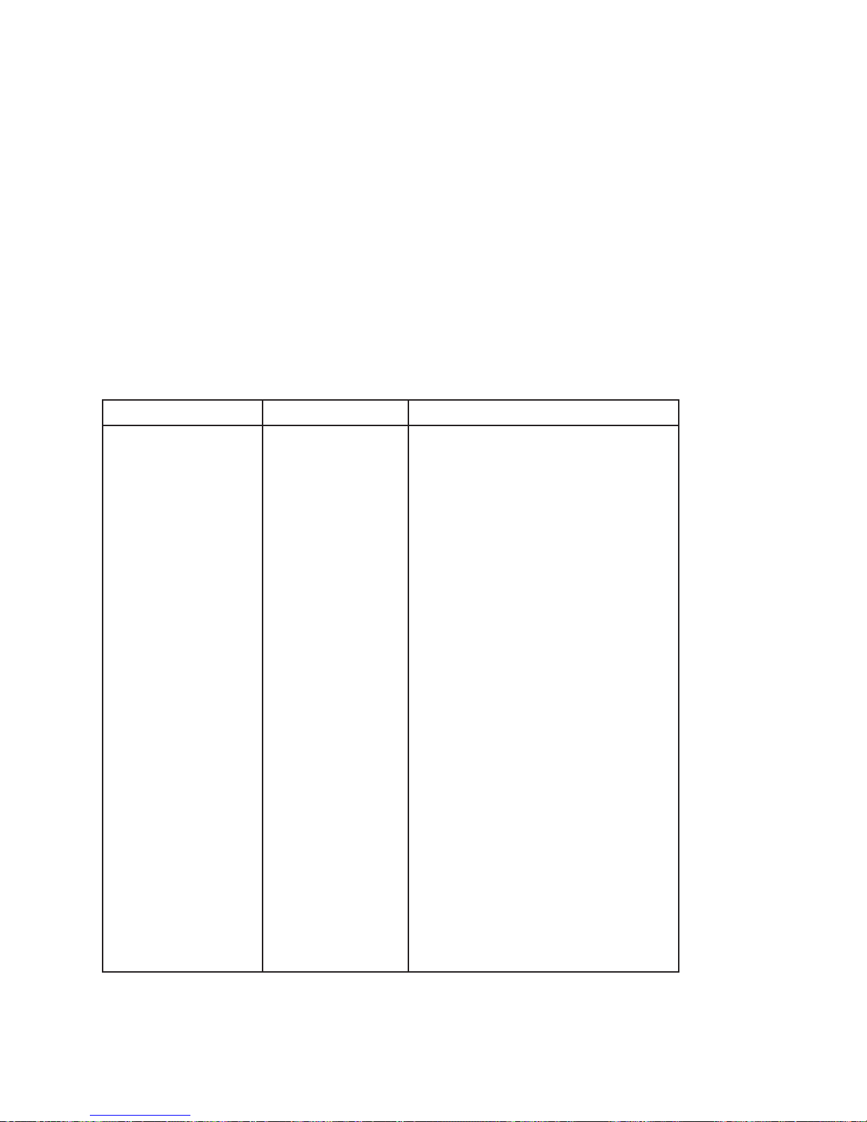
This section shows how the RS-449/530/MIL Interface
can be used with the FIREBERD 4000 in a variety of test
scenarios. Test and instrument set-ups are provided for:
(1) Testing the Near-End Modem (Local Loopback)
or the Far-End Modem (Remote Loopback)
(2) Testing a Far-End 64 kb/s Sub-Rate Channel (Re-
mote Loopback)
(3) Testing Near- and Far-End 256 kb/s Equipment
Simultaneously
(4) Testing a 1200 b/s Asynchronous Modem (Local
Loopback)
NOTE: The combination of test applications is purely arbi-
trary. The procedures in this section are written so
that a variety of applications could be described. Any
combination is possible, depending on the available
facilities.
The procedures in this section assume that you possess a
working knowledge of the RS-449/530/MIL Interface and the
FIREBERD. If you are unfamiliar with the instruments,
please refer to Section 3, Installation and Operation.
4.2 SYNCHRONOUS TESTING
4.2.1 Testing the Near-End Modem (Local
Loopback) or the Far-End Modem (Remote
Loopback)
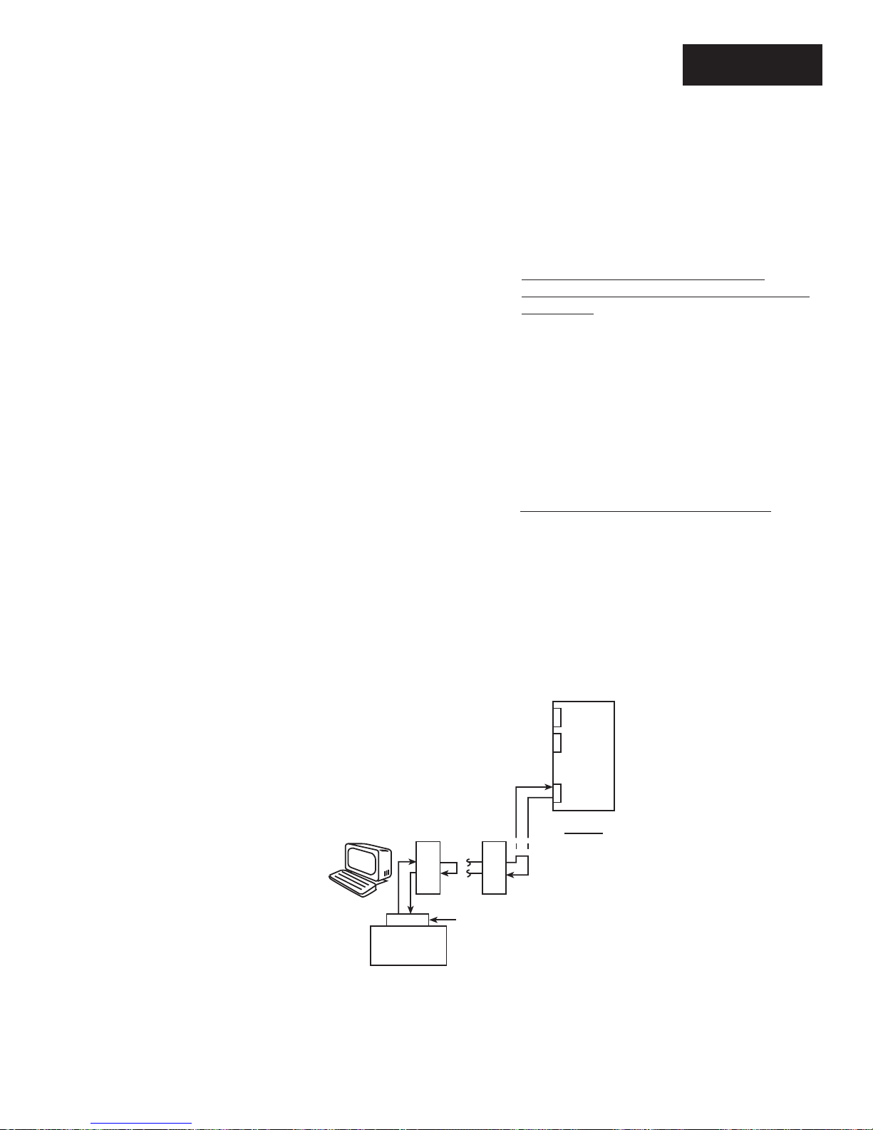
Figure 4-1 shows a FIREBERD 4000 with the RS-449/
530/MIL Interface. The instrument is connected to a near-end
9600 b/s modem (MODEM #1) and a far-end 9600 b/s modem
(MODEM #2). By looping either modem output back to its
own input the FIREBERD can transmit test data to either the
local modem or the remote modem and analyze the loopedback data for errors.
4.2.2 Testing the Far-End Subrate Channel
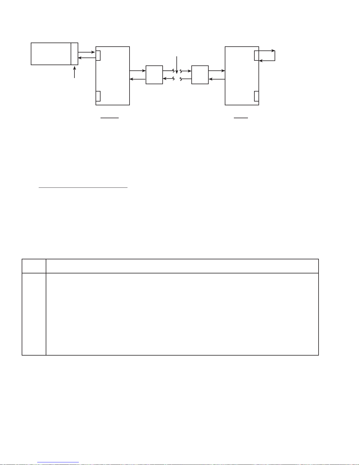
Figure 4-2 shows a FIREBERD 4000 equipped with the
RS-449/530/MIL Interface testing a far-end sub-rate channel
by creating a remote loopback. The instrument is connected
to a 64 kb/s sub-rate channel of a multiplexer on the near side.
The far-end multiplexer has its 64 kb/s sub-rate channels
output connected to its own input to form a loop. The
FIREBERD generates data and analyzes the received data for
errors.
TELECOMMUNICATIONS TECHNIQUES CORPORATION
Multiplexer
9600 b/s
9600
FIREBERD
#1
b/s
Modem 1
9600
b/s
Modem 2
RS449/530/MIL
Near End
9500395-00
Figure 4-1
Local and Remote Loopback Testing
25
Page 32
FIREBERD
#1
64 kb/s
Multichannel
Network
64 kb/s
Loopback
Multiplexer
RS449/530/MIL
Near End
CSU CSU
Figure 4-2
Testing a Far-End Subrate Channel
4.2.3 Basic Synchronous Test Set-Up
Table 4-1 describes the FIREBERD 4000 set-up procedures for the two basic bit error rate tests described in this
section. Although these procedures specifically apply to the
Table 4-1
FIREBERD 4000 Synchronous Test Set-Up With EIA-530
Multiplexer
Far End
9500396-00
testing of modems and multiplexers using the EIA-530 connector, you can use them to set up any basic synchronous test
using the RS-449/530/MIL Interface.
Step Activity
1. With the power to the FIREBERD 4000 turned off, insert the RS-449/530/MIL Data Interface in the designated
rear-panel slot.
2. Press the POWER switch to apply power to the FIREBERD 4000.
RESULT: The SETUP display shows the units current configuration.
NOTE: If the FIREBERD 4000 is in Self-Loop mode after power-up, disengage the SELF LOOP switch.
3. Set the SETUP CATEGORY switch from SETUP SUMMARY category to the INTERFACE category.
26
TELECOMMUNICATIONS TECHNIQUES CORPORATION
Page 33

Table 4-1
FIREBERD 4000 Synchronous Test Set-Up With EIA-530 (Continued)
Step Activity
4. Using the SETUP SELECT switch and the softkeys underneath the SETUP display, configure the INTERFACE
SETUP menu as follows:
NOTE: Unless indicated, press the right half of the SETUP SELECT switch once between selections.
Select:
1. MIL449 to select the RS-449/530/MIL Interface.
2. EIA530 to select the type of interface.
3. DTE to select DTE emulation.
4. BAL to select balanced mode.
5. IMPEDANCE as required (78, 100, 124, or UNTERM).
6. SYNC to select synchronous timing.
7. Select LL (Local Loop) or RL (Remote Loop) ON or OFF depending on the test.
8. ON to select Signaling positive.
5. Set the SETUP CATEGORY switch from INTERFACE SETUP category to the GENERATOR CLOCK
category.
6. Set the GENERATOR CLOCK to INTF to receive the clock from the DCE.
7. Set the SETUP CATEGORY switch from GENERATOR CLOCK category to the PATTERN category.
8. Using the MORE key and the appropriate softkey, select a test data pattern.
NOTE: If transmitting test data to either the local modem or the remote modem as shown in Figure 4-1, select
either the 511, or the 2047 data pattern.
NOTE: If testing a 64 kb/s subrate channel as shown in Figure 4-2, it is recommended to select 2047 or 2
15
-1
data pattern.
9. If hard copy test results are desired, set the PRINTER switch to print on a time interval (15 MIN or 1 HR) or on
the occurrence of any error condition (ERROR).
NOTE: Both error and time print events can be customized using the AUX PRINT EVENT auxiliary function.
See Section 3 of the FIREBERD 4000 Reference Manual for detailed instructions.
10. Press the RTS and DTR switches (located to the right of the VOLUME control) to set both signaling leads HIGH.
Both switches will illuminated.
11. Using the appropriate cables, connect the FIREBERD 4000 to the equipment under test.
12. If performing a loopback test, establish a loop by performing the procedures which are appropriate for your DCE.
13. Check that the PATTERN SYNC and CLOCK PRES LEDs located at the upper right-hand corner of the
FIREBERD 4000 are illuminated.
RESULT: The FIREBERD 4000 has achieved pattern synchronization, and is gathering test results.
TELECOMMUNICATIONS TECHNIQUES CORPORATION
27
Page 34
4.2.4 End-to-End Synchronous Testing
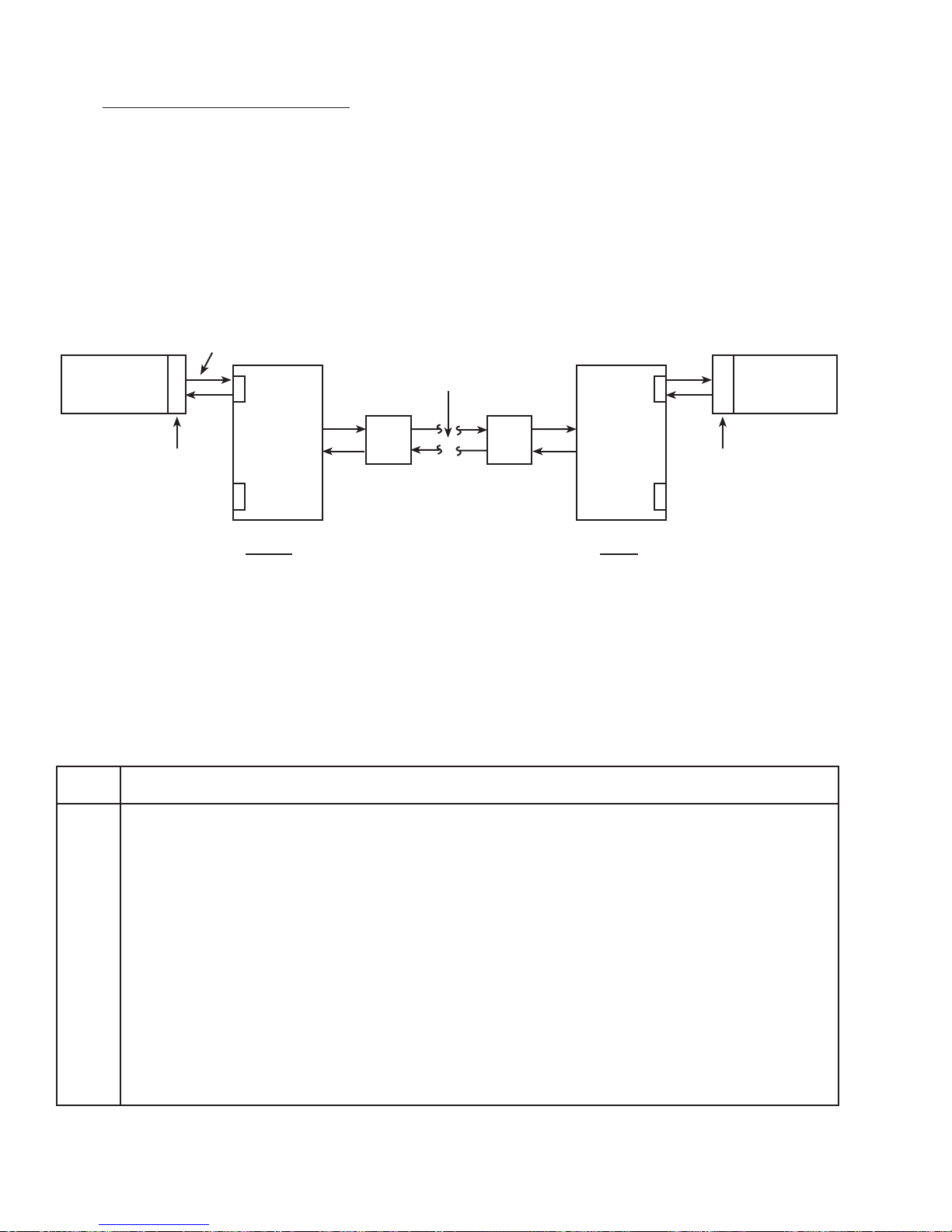
Figure 4-3 shows two FIREBERD 4000s, each equipped
with the RS-449/530/MIL Interface. FIREBERD #1 connects
to the 256 kb/s subrate channel of the multiplexer at the near
end. FIREBERD #2 connects to the 256 kb/s sub-rate channel
of the multiplexer at the far end. Both instruments simultaneously generate test data and analyze received data for errors
in both directions.
256 kb/s
FIREBERD
#1
Multichannel
The test results obtained in this configuration reflect the
quality of all the lines and equipment between the two
FIREBERDS.
Table 4-2 describes the FIREBERD 4000 setup procedures for the bit error rate test illustrated in Figure 4-3.
Although these procedures specifically apply to the testing of
modems and multiplexers using the RS-449 connector, you
can use them to set up any basic synchronous test using the
RS-449/530/MIL Interface.
Network
FIREBERD
#2
RS449/530/MIL
Multiplexer
Near End
CSU CSU
Multiplexer
RS449/530/MIL
Far End
Figure 4-3
Testing Near- and Far-End Subrate Equipment Simultaneously
Table 4-2
FIREBERD 4000 Synchronous Test Set-Up With RS-449
Step Activity
1. With the power to the FIREBERD 4000 turned off, insert the RS-449/530/MIL Data Interface in the designated
rear-panel slot.
2. Press the POWER switch to apply power to the FIREBERD 4000.
9500397-00
RESULT: The SETUP display shows the units current configuration.
If the FIREBERD 4000 is in Self-Loop mode after power-up, disengage the SELF LOOP switch.
3. Set the SETUP CATEGORY switch to the INTERFACE category.
4. Using the SETUP SELECT switch and the softkeys underneath the SETUP display, configure the INTERFACE
SETUP menu as follows:
NOTE: Unless indicated, press the right half of the SETUP SELECT switch once between selections.
28
TELECOMMUNICATIONS TECHNIQUES CORPORATION
Page 35

Table 4-2
FIREBERD 4000 Synchronous Test Set-Up With RS-449 (Continued)
Step Activity
Select:
1. MIL449 to select the RS-449/530/MIL Interface.
2. RS449 to select the type of interface.
3. D-TYPE to select the type of connector.
4. DTE to select DTE emulation.
5. BAL to select balanced mode.
6. IMPEDANCE as required (78, 100, 124, or UNTERM)
7. SYNC to select synchronous timing.
8. Select LL (Local Loop) or RL (Remote Loop) ON or OFF depending on the test.
9. ON to select Signaling positive.
5. Set the SETUP CATEGORY switch to the GENERATOR CLOCK category.
6. Set the GENERATOR CLOCK to INTF to receive the clock from the DCE.
7. Set the SETUP CATEGORY switch to the PATTERN category.
8. Using the MORE key and the appropriate softkey, select a test data pattern.
NOTE: If testing a 256 kb/s subrate channel as shown in Figure 4-3, select either the 511 or the 2047 data pattern.
9. If hard copy test results are desired, set the PRINTER switch to print on a time interval (15 MIN or 1 HR) or on
the occurrence of any error condition (ERROR).
NOTE: Both error and time print events can be customized using the AUX PRINT EVENT auxiliary function.
See Section 3 of the FIREBERD 4000 Reference Manual for detailed instructions.
10. Press the RTS and DTR switches (located to the right of the VOLUME control) to set both signaling leads HIGH.
Both switches will illuminated.
11. Using the appropriate cables, connect the FIREBERD 4000 to the equipment under test.
12. If performing a looopback test, establish a loop by performing the procedures which are appropriate for your
DCE.
13. Check that the PATTERN SYNC and CLOCK PRES LEDs located at the upper right-hand corner of the
FIREBERD 4000 are illuminated.
RESULT: The FIREBERD 4000 has achieved pattern synchronization, and is gathering test results.
TELECOMMUNICATIONS TECHNIQUES CORPORATION
29
Page 36
4.2.5 Synchronous Test Results
Table 4-3 lists the significant synchronous test results
that are available with the RS449/MIL Data Interface. These
results can be collected via printer or can be viewed at the
ANALYSIS display windows.
1200 b/s
Modem 1
Loopback
4.3 ASYNCHRONOUS TESTING
4.3.1 Testing a 1200 b/s Asynchronous Modem
(Local Loopback)
Figure 4-4 shows a FIREBERD 4000 equipped with the
RS-449/530/MIL Interface. The instrument is connected to a
1200 b/s modem which has its output looped back to its own
input. The FIREBERD 4000 both transmits the test data and
analyzes the received data for errors.
Table 4-3
FIREBERD 4000 Synchronous Test Results
Category Results
ERROR BER BLOCKS BLK ERRS
AVG BLER CLK SLIP BIT ERRS
AVG BER PAT LOSS PAT SLIP
PERFORMANCE
1
GERR SEC GEFS G %EFS
DEG MIN %DEG MIN SES
%SES UNA SEC AVL SEC
%AVL SEC
FIREBERD
Figure 4-4
Testing an Asynchronous Modem
RS449/530/MIL
9500398-00
2
TIME & SIGNAL ERR SEC TEST SEC %EFS
ELAP SEC TIME DATE
PATL SEC DELAY
GEN FREQ
1
Requires option 4004
2
Synchronous timing with pseudorandom timing only
3
DTE only
30
3
TELECOMMUNICATIONS TECHNIQUES CORPORATION
RCV FREQ
Page 37

Table 4-4
FIREBERD 4000 Asynchronous Test Set-Up With 188C
Step Activity
1. With the power to the FIREBERD 4000 turned off, insert the RS-449/530/MIL Data Interface in the designated
rear-panel slot.
2. Press the POWER switch to apply power to the FIREBERD 4000.
RESULT: The SETUP display shows the units current configuration.
If the FIREBERD 4000 is in Self-Loop mode after power-up, disengage the SELF LOOP switch.
3. Set the SETUP CATEGORY switch to the INTERFACE category.
4. Using the SETUP SELECT switch and the softkeys underneath the SETUP display, configure the INTERFACE
SETUP menu as follows:
NOTE: Unless indicated, press the right half of the SETUP SELECT switch once between selections.
Select:
1. MIL449 to select the RS-449/530/MIL Interface.
2. 188C to select the type of interface.
3. DTE to select DTE emulation.
4. ASYNC to select asynchronous timing.
5. DATA BITS as required (5, 6, 7, or 8).
6. PARITY as required (ODD, EVEN, or NONE).
7. STOP BITS as required (1, 1.5, or 2).
8. Select LL (Local Loop) or RL (Remote Loop) ON or OFF depending on the test.
9. ON to select Signaling positive.
5. Set the SETUP CATEGORY switch to the GENERATOR CLOCK category.
6. Set the GENERATOR CLOCK to INTRNL position.
7. Using the SETUP SELECT switch and the appropriate softkey, set the INTERNAL FREQ to 1.2 k.
8. Set the SETUP CATEGORY switch to the PATTERN category.
9. Using the MORE key and the appropriate softkey, select the FOX data pattern.
10. If hard copy test results are desired, set the PRINTER switch to print on a time interval (15 MIN or 1 HR) or on
the occurrence of any error condition (ERROR).
NOTE: Both error and time print events can be customized using the AUX PRINT EVENT auxiliary function.
See Section 3 of the FIREBERD 4000 Reference Manual for detailed instructions.
11. Press the RTS and DTR switches (located to the right of the VOLUME control) to set both signaling leads HIGH.
Both switches will illuminated.
12. Using the appropriate cables, connect the FIREBERD 4000 to the equipment under test.
13. If performing a looopback test, establish a loop by performing the procedures which are appropriate for you DCE.
14. Check that the PATTERN SYNC and CLOCK PRES LEDs located at the upper right-hand corner of the
FIREBERD 4000 are illuminated.
RESULT: The FIREBERD 4000 has achieved pattern synchronization, and is gathering test results.
TELECOMMUNICATIONS TECHNIQUES CORPORATION
31
Page 38

4.3.2 Asynchronous Test Results
Table 4-5 lists the significant asynchronous test results
that are available with the RS449/MIL Data Interface. These
results can be collected via printer or can be viewed at the
ANALYSIS display windows.
Table 4-5
FIREBER 4000 Asynchronous Test Results
Category Results
ERROR BIT ERRS AVG BER BER
BLOCKS BLK ERRS AVG BLER
CHAR ERR PAT LOSS
PERFORMANCE
1
UNA SEC %AVL SEC DEG MIN
AVL SEC SES %SES
%DEG MIN SYNL SEC %SYN SEC
G %EFS GERR SEC G EFS
TIME & SIGNAL ERR EAS E A SEC E F EAS
ELAP SEC TIME DATE
PATL SEC ERR SEC %EFS
DELAY
2
GEN FREQ TEST SEC
ELAP SEC
1
Requires option 4004
2
DTE only
32
TELECOMMUNICATIONS TECHNIQUES CORPORATION
Page 39
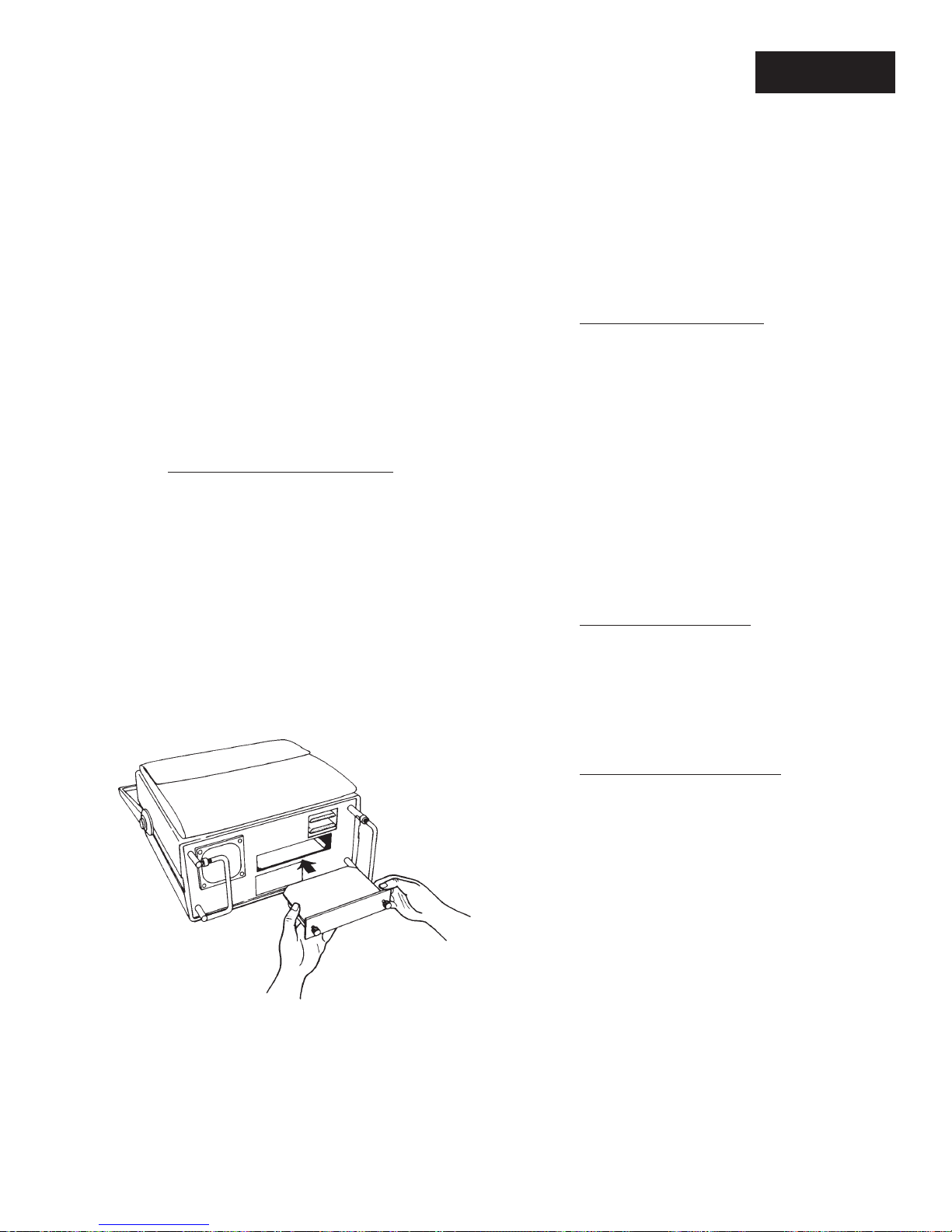
FIREBERD 6000
INSTALLATION AND OPERATION
SECTION 5
5.1 INTRODUCTION
This section describes how to install, configure, and operate
the RS-449/530/MIL Data Interface with a FIREBERD 6000.
Refer to the FIREBERD 6000 User’s Guide or the FIREBERD
6000 Reference Manual for mainframe operating procedures.
NOTE: Configure the FIREBERD 6000 and the RS-449/
530/MIL Data Interface before connecting the
FIREBERD to the circuit under test. This avoids
unnecessary circuit downtime.
5.1.1 Repair and Replace Procedure
The RS-449/530/MIL Data Interface, Model 41400, is
provided as a self-contained unit. If repairs are necessary, the
entire interface should be replaced. Section 8 of this manual
contains information about the warranty and return policies.
5.2 INSTALLING THE INTERFACE
The following procedure describes how to install the
RS-449/530/MIL Data Interface in the FIREBERD 6000.
Figure 5-1 illustrates how the interface is installed.
CAUTION: Before installing or removing the interface mod-
ule, turn the AC power OFF to the FIREBERD
mainframe. Damage can occur to the interface
and mainframe.
5.2.1 Performance Verification
The proper performance of the RS-449/530/MIL Data
Interface, Model 41400, is verified by installing the interface
in the FIREBERD 6000 as described in the previous paragraphs. The FIREBERD 6000 should be set-up as described
in the step-by-step procedures in the following paragraphs.
The equipment should be powered-up and the various menus
and set-ups performed to ensure proper operation. If any test
fails, be sure to check connections, continuity of cables, and
proper seating of the interface into results section at the back
of this section. In addition, the FIREBERD 6000 Reference
Manual provides additional performance verification and
validation results.
5.2.2 Calibration Procedures
The RS-449/530/MIL Data Interface, Model 41400, is
factory checked and requires no calibration. The FIREBERD
6000 is calibrated as described in the FIREBERD 6000
Reference Manual.
Figure 5-1
Installing a Modular Interface
TELECOMMUNICATIONS TECHNIQUES CORPORATION
9500399-00
5.2.3 Parts List and Vendors List
No parts list or vendors list is provided because the RS-449/
530/MIL Data Interface, Model 41400, is the LRU. See Section
8 of this manual for replacement and warranty information.
1. Power OFF the FIREBERD.
2. Face the FIREBERD rear panel.
3. Insert the interface into the vacant interface slot.
Verify that the interface faces up.
4. Slide the module into the FIREBERD until the
interface panel is flush with the rear panel. Make
sure the PC board edges are fitted into the card guides
inside the interface slot.
5. Secure the interface with the two thumbscrews on
the interface panel.
33
Page 40

5.3 FIREBERD 6000 MAINFRAME SET-UP
Perform this procedure to configure the FIREBERD
6000 with the RS-449/530/MIL Interface.
(5) If the AUX FUNC IN USE indicator is illuminated
scroll through the Auxiliary Function IN USE list to
identify auxiliary functions that might affect the
operation of the RS-449/530/MIL Interface.
(1) Turn the AC power ON. If necessary, release the
SELF LOOP pushbutton before starting.
(2) Set the DATA switch to the appropriate test pattern.
Refer to the FIREBERD 6000 Reference Manual for
descriptions of the test patterns.
(3) Set the GEN CLK switch to the appropriate genera-
tor clock source:
SYNTH - If the synthesizer is selected, use the
MENU switch to select the SYNTH FREQ (synthesizer frequency) menu. Select the desired frequency
from the softkeys or enter it through the keypad from
50 k b/s to 15 Mb/s.
INTF - Provides the generator clock through the
interface received clock in synchronous mode and in
recovered clock mode.
BNC - Allows an input from an external clock source.
The external clock source is input through the GEN
CLK IN connector on the rear panel.
(4) Set the TIMING MODE switch to the appropriate
timing mode as required:
SYNC - Selects the synchronous timing mode. With
synchronous timing, operation to 15 Mb/s is possible. The default is SYNC.
ASYNC - Select the asynchronous timing mode.
Asynchronous timing is limited to data rates up to 20
kb/s. The following PATTERNs are valid in asynchronous testing: MARK, SPACE, 1:1, 63, 511,
2047, 215-1, FOX, and USER 1-3. When using
asynchronous timing, set the MENU switch to the
CHAR FORMAT menu to select DATA BITS,
PARITY, and STOP BITS.
(6) Select the desired ANALYSIS MODE: CONTINU-
OUS or SINGLE.
(7) Select the applicable categories and results displays
from the ANALYSIS RESULTS panel.
5.4 FIREBERD 6000 INTERFACE SET-UP
This section describes how to access the interface menu
and discusses each of the menu selections in the RS-449/530/
MIL Data Interface menu.
The RS-449/530/MIL Data Interface is controlled through
the FIREBERD 6000 INTERFACE SETUP category. Press
the MIL449 softkey to access the MIL449 interface menu.
Press the appropriate softkey to select a function or another
menu. To return to the previous menu display press the
mainframe keypad “up arrow” key. To return to the main
interface menu, press the mainframe ENTER key. Press the
softkeys to select a function as indicated by the softkey labels
on the bottom line of the display. All interface menu settings
are retained when power is removed from the mainframe. See
Figures 5-2 through 5-5 for the interface menus.
5.4.1 Operating Type Menu
The Operating Type (TYPE) menu allows the user to
select either MIL188114, RS449, EIA530, or MIL188C as the
type of interface operation. Press the appropriate softkey to
select the desired operating type. Press the MORE key to
display the 188C softkey label. Modifying TYPE will cause
a test restart.
188114 - The 188114 operating type configures the
interface to be connected to a MIL188-114 compatible
circuit.
RECOVD - Selects the recovered timing mode.
34
RS449 - The RS449 operating type configures the inter-
face to be connected to a RS-449 compatible circuit.
EIA530 - The EIA530 operating type configures the
interface to be connected to a EIA-530 compatible
circuit.
188C - The 188C operating type configures the interface
to be connected to a MIL188C compatible circuit.
TELECOMMUNICATIONS TECHNIQUES CORPORATION
Page 41
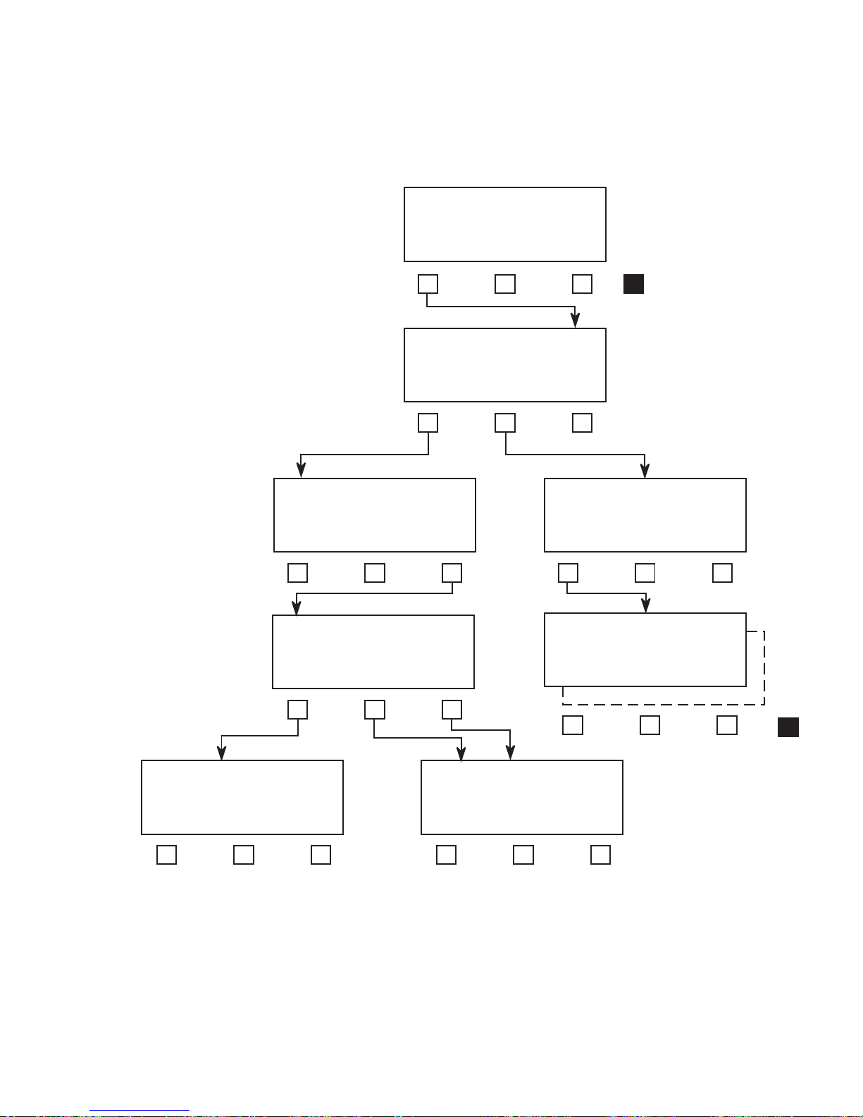
INTERFACE: MIL449
188114 RS449 EIA530
TYPE: 188114
CON MODE
CONNECTOR: TWINAX
TWINAX D-TYPE
EMULATE: DTE
MORE
MODE: BAL
BAL UNBAL
IMPEDANCE:
DTE DCE-TT DCE-ST
SIG:POS LL:OFF RL:OFF
SIG LL RL
POS
NEG
ON
OFF
ON
OFF
SIG:POS TM:OFF CTS:OFF
SIG TM CTS
Figure 5-2
FIREBERD 6000 RS-449/530/MIL Interface Set-Up Menu
Type 188114
TELECOMMUNICATIONS TECHNIQUES CORPORATION
POS
NEG
78 100 124
UNTERM
ON
OFF
ON
OFF
MORE
9500400-00
35
Page 42
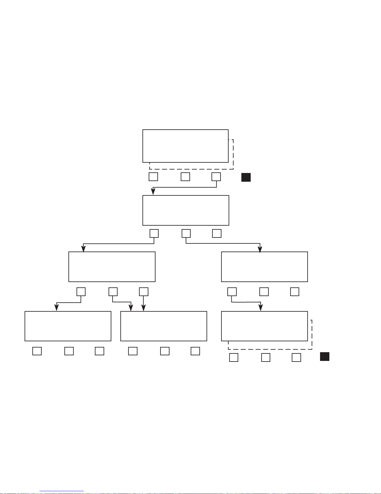
INTERFACE: MIL449
188114 RS449 EIA530
188C
TYPE: EIA530
EMLATE MODE
MORE
EMULATE: DTE
DTE DCE-TT DCE-ST
SIG:POS LL:OFF RL:OFF
SIG:POS LL:OFF RL:OFF
SIG LL RL
SIG LL RL
POS
NEG
ON
OFF
ON
OFF
FIREBERD 6000 RS-449/530/MIL Interface Set-Up Menu
SIG:POS TM:OFF CTS:OFF
SIG TM CTS
POS
NEG
ON
OFF
ON
OFF
Figure 5-3
MODE: BAL
BAL UNBAL
IMPEDANCE:
78 100 124
UNTERM
9500401-00
MORE
36
TELECOMMUNICATIONS TECHNIQUES CORPORATION
Page 43
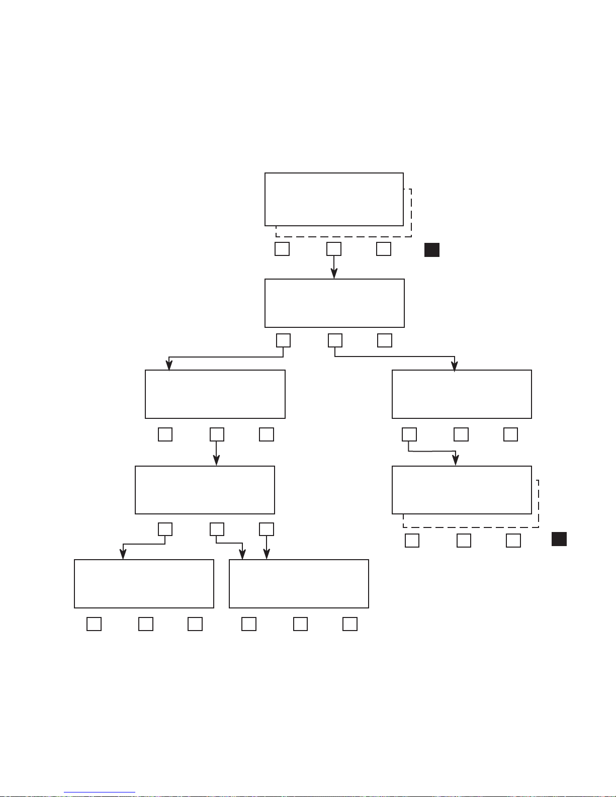
INTERFACE: MIL449
188114 RS449 EIA530
188C
TYPE: RS449
CON MODE
MORE
CONNECTOR: TWINAX
TWINAX D-TYPE
EMULATE: DTE
DTE DCE-TT DCE-ST
SIG:POS LL:OFF RL:OFF
SIG LL RL
POS
NEG
ON
OFF
ON
OFF
SIG:POS TM:OFF CTS:OFF
SIG TM CTS
POS
NEG
ON
OFF
ON
OFF
MODE: BAL
BAL UNBAL
IMPEDANCE:
78 100 124
UNTERM
9500402-00
MORE
FIREBERD 6000 RS-449/530/MIL Interface Set-Up Menu
TELECOMMUNICATIONS TECHNIQUES CORPORATION
Type EIA-530
Figure 5-4
37
Page 44
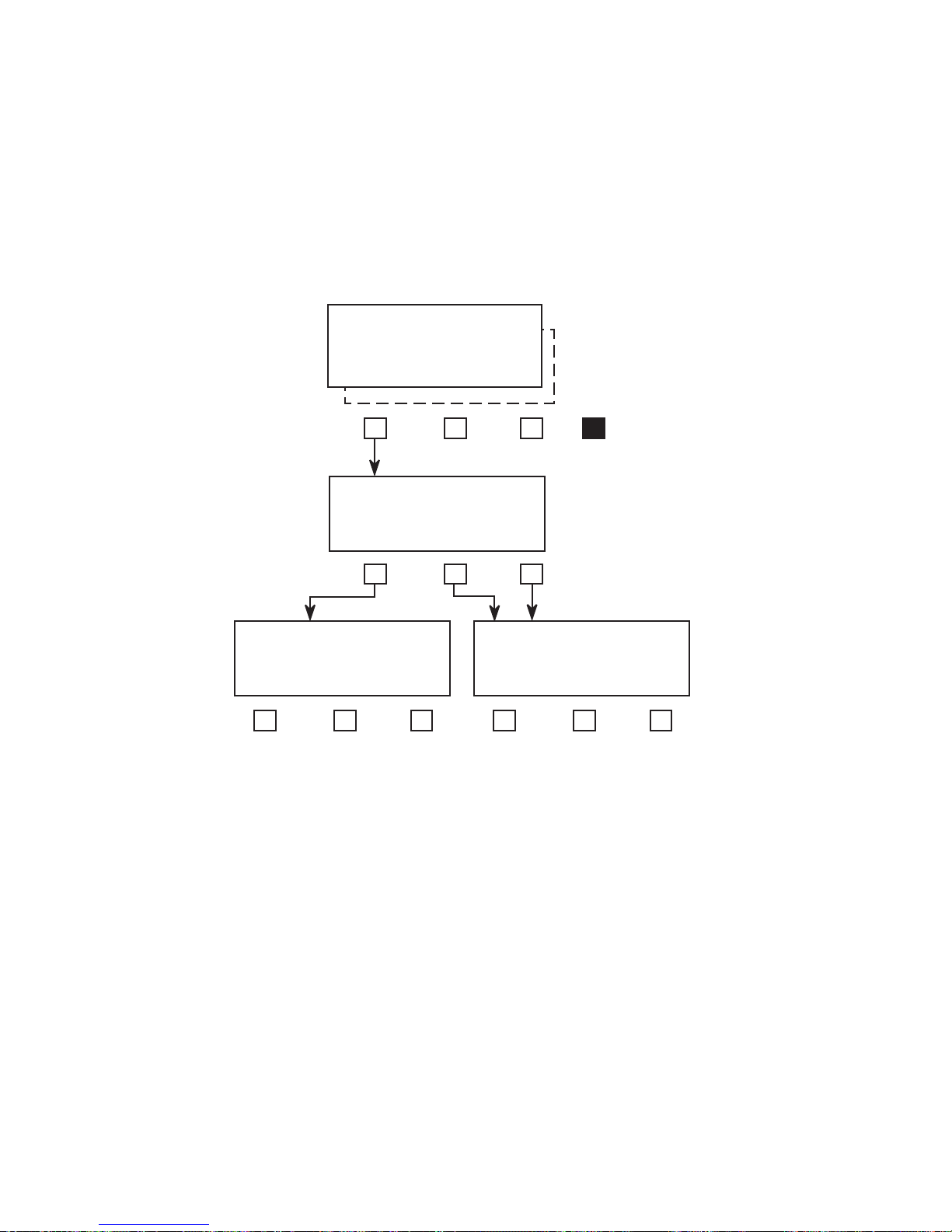
INTERFACE: MIL449
188114 RS449 EIA530
188C
EMULATE: DTE
DTE DCE-TT DCE-ST
SIG:POS LL:OFF RL:OFF
SIG LL RL
POS
NEG
ON
OFF
ON
OFF
MORE
SIG:POS TM:OFF CTS:OFF
SIG TM CTS
POS
NEG
ON
OFF
ON
OFF
9500403-00
FIREBERD 6000 RS-449 /530/MIL Interface Set-Up Menu
38
Type RS449
Figure 5-5
Type 188C
TELECOMMUNICATIONS TECHNIQUES CORPORATION
Page 45

5.4.2 Connector Menu
The Connector (CONNECTOR) menu only appears when
TYPE 188114 or TYPE RS449 is selected. This menu
controls the type of data interface which the FIREBERD can
be connected to. Modifying CONNECTOR causes a test
restart. Pressing the associated softkey selects either D-TYPE
or TWINAX.
D-TYPE - When the D-TYPE softkey is pressed, the
interface is configured to use the RS-449/MIL188-114,
37-pin connector.
TWINAX - When the TWINAX softkey is pressed, the
interface is configured to use the twinax connectors.
5.4.3 Emulate Menu
The Emulate (EMULATE) menu establishes the interface emulation mode. Pressing the associated softkey selects
either DTE or DCE emulation. This menu does not appear
when the selected CONNECTOR is TWINAX.
DTE - This selection allows the FIREBERD mainframe
to emulate DTE.
DCE-TT - This selection allows the FIREBERD main-
frame to emulate DCE with Terminal Timing as the
timing reference that the mainframe synchronizes to. In
Terminal Timing the receiver timing source comes from
Pin 24 (EIA530/MIL188C) or Pin 17 (RS-449/MIL188-
114).
DCE-ST - This selection allows the FIREBERD main-
frame to emulate DCE with Send Timing as the timing
reference that the mainframe synchronizes to. In Send
Timing the receiver timing source is the mainframe
generator clock that is sent out on Pin 15 (EIA530/
MIL188C) or Pin 5 (RS-449/MIL188-114).
5.4.4 Mode Menu
The Mode (MODE) menu allows the user to select
between balanced and unbalanced operation. Modifying
MODE causes a test restart.
IMPEDANCE - This menu allows you to select either a
termination impedance of 78 ohms, 100 ohms, 124 ohms,
or UNTERM (>7.4 k ohms).
UNBAL - This selection allows the FIREBERD to operate
in an unbalanced mode. In unbalanced mode each signal
is transmitted on one lead with respect to a common
ground.
5.4.5 Signaling Menu
TM:OFF|ON CTS:OFF|ON - This menu only appears
when the mainframe is configured for D-TYPE CONNECTOR and DCE EMULATION. The operation of
TM (Test Mode) lead [Pin 25 (EIA530/MIL188C) or Pin
18 (RS-449/MIL188-114)] and the operation of the CTS
(Clear To Send) lead [Pin 5 (EIA530/MIL188C) or Pin 9
(RS-449/MIL188-114)] are controlled by this menu. Press
the TM softkey to toggle the TM lead ON and OFF. ON
equals a logic HIGH. OFF equals a logic LOW. Press the
CTS softkey to toggle the CTS lead ON and OFF. ON
equals a logic HIGH. OFF equals a logic LOW.
LL:OFF|ON RL:OFF|ON - This menu only appears when
the mainframe is configured for D-TYPE CONNECTOR
and DTE EMULATION. The operation of the LL (Local
Loopback) lead [Pin 18 (EIA530/MIL188C) or Pin 10
(RS-449/MIL188-114)] and RL (Remote Loopback) lead
[Pin 21 (EIA530/MIL188C) or pin 18 (RS-449/MIL188-
114)] are controlled by this menu. Press the LL softkey
to toggle the LL lead ON and OFF. ON equals a logic
HIGH. OFF equals a logic LOW. Press the RL softkey
to toggle the RL lead ON and OFF. ON equals a logic
HIGH. OFF equals a logic LOW.
SIG:POS|NEG - This menu only appears when the D-
TYPE CONNECTOR is selected. This menu controls the
polarity of all the interface signaling control leads. Press
the appropriate softkey to set SIG to POS (positive) or
NEG (negative) polarity. Selecting POS sets the ON
condition to a positive value and an OFF condition to a
negative value. Selecting NEG sets the ON condition to
a negative value and an OFF condition to a positive value.
BAL - This selection allows the FIREBERD to operate in
a balanced mode. Balanced mode indicates that each
signal is transmitted on two leads in which the voltage is
equal in magnitude and opposite in polarity with respect
to a common reference. This mode is preferred when
minimum noise and cross talk is desired. When balanced
mode is selected the following menu is provided to set the
termination impedance. The termination impedance
should be set to match the characteristics of the cable.
TELECOMMUNICATIONS TECHNIQUES CORPORATION
5.5 FIREBERD 6000 ANALYSIS RESULTS
Table 5-1 lists the analysis results that are displayed when
the RS-449/530/MIL Data Interface is installed in the
FIREBERD 6000. Refer to the FIREBERD 6000 Reference
Manual for results definitions.
39
Page 46
Table 5-1
FIREBERD 6000 Analysis Results
Category Displayed Result Description
ERROR AVG BER Average Bit Error Rate
AVG BLER Average Block Error Rate
BER Bit Error Rate
BIT ERRS Bit Errors
BLOCKS Blocks
BLK ERRS Block Errors
CHAR ERR Character Error**
PAT SLIP Pattern Slips*
TIME DATE Date
EA SEC Error Analysis Seconds
EF EAS Error-Free Error Analysis Seconds
ELAP SEC Elapsed Seconds
ERR EAS Errored Error Analysis Seconds
PATL SEC Pattern Loss Seconds
%PAT SEC %Pattern Loss Seconds
TIME Time
SIGNAL DELAY Delay
GEN FREQ Generator Frequency
RCV FREQ Receiver Clock Frequency*
ALARM C-D CHA Receiver Clock-Data Phase Changes***
CLK LOSS Receiver Clock Losses***
DAT LOSS Receiver Data Losses
PAT LOSS Pattern Synchronization Loss
PWR LOSS Power Losses
PERFORMANCE* AVL SEC Available Seconds
%AVL SEC % Available Seconds
%DEG MIN % Degraded Minutes
%PAT SEC %Pattern Seconds
%SES % Severely Errored Seconds
BER-SES BIT Error Rate Minus Severely Errored Seconds
DEG MIN Degraded Minutes
ERR-SES Errors Minus Severely Errored Seconds
G EFS G.821 Percent of Error Free Seconds
GERR SEC G.821 Errored Seconds
G %EFS G.821 Percent of Error Free Seconds
SES Severely Errored Seconds
UNA SEC Unavailable Seconds
If not indicated - Available with Synchronous, Asynchronous, and Recovered Timing
*Available with Synchronous and Recovered Timing
**Available with Asynchronous Timing Only
***Available with Synchronous Timing Only
40
TELECOMMUNICATIONS TECHNIQUES CORPORATION
Page 47

5.6 FIREBERD 6000 SELF-LOOP TEST
The RS-449/530/MIL Data Interface includes a relay that
is activated by the SELF LOOP pushbutton switch on the
FIREBERD front panel. Pressing the SELF LOOP pushbutton
connects the transmit clock and data to the receive clock and
data. This provides quick verification of the FIREBERD and
the data interface. User connections do not need to be
removed during the test, since complete isolation is provided
by the relay when testing in the Self-Loop mode.
5.7 INTERFACE STATUS INDICATORS AND
SWITCHES
Depending on the EMULATE selection (DTE or DCE)
the corresponding front panel interface status and control
panel label will illuminate. The LEDs to the right of these
labels indicate activity on the associated interface connector
lines. The following describes what each LED indicates. The
DTE and DCE emulation labels not in parentheses indicate
EIA 530/MIL-188C lead notation and the labels in parentheses indicate RS-449/MIL188-114 lead notation.
Switches
RLSD (RR) - In DCE emulation the pushbutton switch
controls the state of the Received Line Signal Detector
line. Pressing the RLDS pushbutton causes it to illumi-
nate, forcing this line ON. When the pushbutton LED is
extinguished, the line is held OFF.
RTS - In DCE emulation, the Request To Send LED
illuminates when this line is ON.
DTR - In DCE emulation, the LED illuminates when this
line is ON.
TM - In DTE emulation, the Test Mode LED illuminates
when this line is ON. In DCE emulation, there is no
corresponding LED.
LL - In DCE emulation, the Local Loopback LED illumi-
nates when this line is ON. In DTE emulation, there is no
corresponding LED.
RL - In DCE emulation, the Remote Loopback LED
illuminates when this line is ON. In DTE emulation, there
is no corresponding LED.
5.8 FIREBERD 6000 PRINTER OPERATION
Refer to the FIREBERD 6000 Reference Manual for
printer set-up and operating instructions. Figure 5-6 is a
typical Controls printout showing a RS-449/530/MIL Data
Interface. Figure 5-7 shows a typical Results printout with the
RS-449/530/MIL Data Interface.
NOTE: Only the interface setting relevant to the current
interface mode are displayed.
DSR (DM) - In DCE emulation, pressing the correspond-
ing pushbutton illuminates the LED and forces the DSR
line ON. Pressing this pushbutton again extinguishes the
LED and the DSR line is held OFF.
RTS - In DTE emulation, pressing the Request To send
pushbutton illuminates the LED and forces this line ON.
Pressing this pushbutton again extinguishes the LED and
holds the line OFF.
DTR - In DTE emulation, pressing this pushbutton illumi-
nates the LED and forces the Data Terminal Ready line
ON.
Indicators
RLSD - In DTE emulation, the Received Line Signal
Detector illuminates when this line is ON.
DSR - In DTE emulation, the Data Set Ready LED
illuminates when this line is ON.
CTS - In DTE emulation, the Clear To Send LED illumi-
nates when this line is ON. In DCE emulation, there is no
corresponding LED.
CONTROLS PRINT
10:33:03 06 DEC 90 SITE: Alpha
DATA: 2^15-1 ERROR INS: OFF
SELF LOOP: ON GEN CLOCK: SYNTH
TIMING MODE: SYNC SYN FRQ: 64 kHz
INTERFACE:
TYPE: RS449 EMULATE: DTE
MODE: BAL IMPEDANCE: 100
CONNECTOR D-TYPE POLARITY: POS
LL: OFF RL: OFF
RTS: OFF DTR: OFF
TEST INT: 10^5 PRINT EVENT: NOR
TEST INT: OFF SYNC LOSS PRNT: OFF
ERROR PRNT: OFF TIME PRNT: OFF
ANALY MODE: CON DISPLAY HOLD: OFF
BLOCK LENGTH: 1000 BITS
DELAY: DTR/ DTR/ XON CHARACTER: 11
XOFF CHARACTER: 13 AUX FUNC IN USE:
NONE PRINT SPEED: FAST
PRINT TERM: CR LF REMOTE: NONE
PRINTER: RS-232 RS-232:
DATA BITS: 8 BAUD: 9600
PARITY: NONE
Figure 5-6
Controls Printout
TELECOMMUNICATIONS TECHNIQUES CORPORATION
41
Page 48

MANUAL PRINT
TIME/DATE 10:34:38 06 DEC 90
BIT ERRS 0 AVG BER 0. E-08
BER 0. E-05 BLOCKS 11542
BLK ERRS 0 AVG BLER 0. E-04
EA SEC 180 ERR EAS 0
EF EAS 180 PAT SLIP 0
ELAP SEC 181 DELAY
RCV FREQ 64000.0 GEN FREQ 64000.0
PAT LOSS 0 DAT LOSS 0
CLK LOSS 0 PWR LOSS 0
C-D CHA 0 PATL SEC 0
%PAT SEC 100.00% ERR-SES 0
BER-SES 0. E-07 AVL SEC 180
%DEG MIN 0.00% %SES 0.00%
G %EFS 100.00% G EFS 180
DEG MIN 0 GERR SEC 0
SES 0 UNA SEC 0
%AVL SEC 100.00% IF RS-449/530/MIL
RR OFF DM OFF
CS OFF TM OFF
RS OFF TR OFF
SELF LOOP ON
Figure 5-7
Results Printout
5.9 FIREBERD 6000 REMOTE CONTROL
COMMANDS
The FIREBERD 6000 remote control commands enable
remote control over the RS-449/530/MIL Data Interface. The
RS-449/530/MIL Data Interface commands are listed in Table
5-2. The commands are in accordance with the IEEE.488.2
specification. The spacing used on each command line must
be used as indicated.
Table 5-2
RS-449/530/MIL Data Interface FIREBERD 6000 Remote Control Commands
Remote Command Result
INTF:MIL449:INTERFACE? Prints current interface type set-up.
INTF:MIL449:INTERFACE [188114|RS449|EIA530|188C] Selects the interface type.
INTF:MIL449:CONNECTOR? Prints the current connector setting.
INTF:MIL449:CONNECTOR [TWINAX|DTYPE] Selects the connector type.
INTF:MIL449:CONNECTOR:DTYPE? Prints the current emulation for the D-Type
connector.
INTF:MIL449:CONNECTOR:DTYPE [DTE|DCE TT|DCE ST] Selects the emulation type for the D-Type
connector.
INTF:MIL449:EMULATE:SIGNAL? Prints the current signaling polarity.
INTF:MIL449:EMULATE:SIGNAL [POSITIVE|NEGATIVE] Selects the signaling polarity POS or NEG.
INTF:MIL449:EMULATE:LL? Prints the current Local Loop status.
INTF:MIL449:EMULATE:LL [ON|OFF] Selects the Local Loop ON or OFF.
INTF:MIL449:EMULATE:RL? Prints the current Remote Loop status.
INTF:MIL449:EMULATE:RL [ON|OFF] Selects the Remote Loop ON or OFF.
INTF:MIL449:EMULATE:TM? Prints the current Test Mode status.
INTF:MIL449:EMULATE:TM [ON|OFF] Selects the Test Mode ON or OFF.
INTF:MIL449:EMULATE:CTS? Prints the current Clear To Send status.
INTF:MIL449:EMULATE:CTS [ON|OFF] Selects the Clear To Send ON or OFF.
INTF:MIL449:MODE? Prints current mode setting.
INTF:MIL449:MODE [BALANCE|UNBALANCE] Selects the mode setting.
INTF:MIL449:BALANCE:IMPEDANCE? Prints the currently selected impedance.
INTF:MIL449:BALANCE:IMPEDANCE [78|100|124|UNTERMINATE] Select the impedance.
42
TELECOMMUNICATIONS TECHNIQUES CORPORATION
Page 49
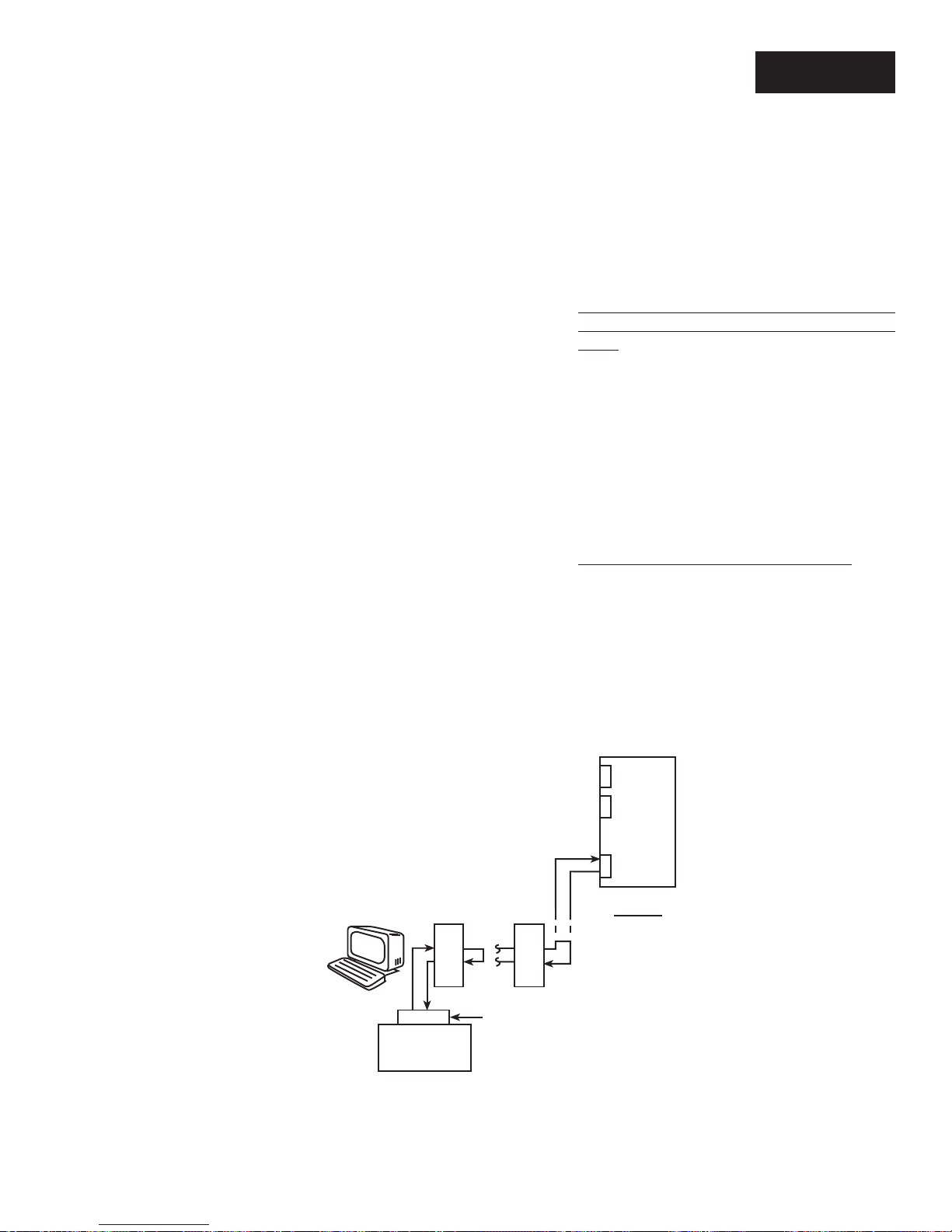
FIREBERD 6000
APPLICATIONS
SECTION 6
6.1 INTRODUCTION
This section shows how the RS-449/530/MIL Interface
can be used with the FIREBERD 6000 in a variety of test
scenarios. Test and instrument set-ups are provided for:
(1) Testing the Near-End Modem (Local Loopback) or
the Far-End Modem (Remote Loopback)
(2) Testing a Far-End 64 kb/s Sub-Rate Channel (Re-
mote Loopback)
(3) Testing Near- and Far-End 256 kb/s Equipment
Simultaneously
(4) Testing a 1200 kb/s Asynchronous Modem (Local
Loopback)
NOTE: The combination of test applications is purely arbi-
trary. The procedures in this section are written so
that a variety of applications could be described.
Any combination is possible, depending on the available facilities.
The procedures in this section assume that you possess a
working knowledge of the RS-449/530/MIL Interface and the
FIREBERD 6000. If you are unfamiliar with the instruments,
please refer to Section 5, Installation and Operation.
6.2 SYNCHRONOUS TESTING
6.2.1 Testing the Near-End Modem (Local Loopback) or the Far-End Modem (Remote Loopback)
Figure 6-1 shows a FIREBERD 6000 with the RS-449/
530/MIL Interface. The instrument is connected to a near-end
9600 b/s modem (MODEM #1) and a far-end 9600 b/s modem
(MODEM #2). By looping either modem output back to its
own input the FIREBERD can transmit test data to either the
local modem or the remote modem and analyze the loopedback data for errors.
6.2.2 Testing the Far-End Subrate Channel
Figure 6-2 shows a FIREBERD 6000 equipped with the
RS-449/530/MIL Interface testing a far-end sub-rate channel
by creating a remote loopback. The instrument is connected
to a 64 kb/s sub-rate channel of a multiplexer on the near side.
The far-end multiplexer has its 64 kb/s sub-rate channels
output connected to its own input to form a loop. The
FIREBERD generates data and analyzes the received data for
errors.
TELECOMMUNICATIONS TECHNIQUES CORPORATION
Multiplexer
9600 b/s
9600
FIREBERD
#1
b/s
Modem 1
9600
b/s
Modem 2
RS449/530/MIL
Near End
9500404-00
Figure 6-1
Local and Remote Loopback Testing
43
Page 50
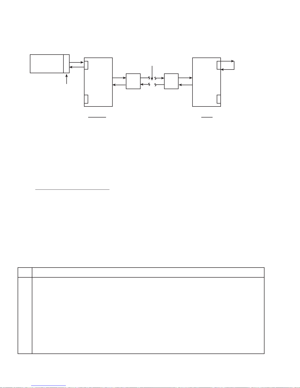
FIREBERD
#1
64 kb/s
Multichannel
Network
64 kb/s
Loopback
Multiplexer
RS449/530/MIL
Near End
CSU CSU
Figure 6-2
Testing a Far-End Subrate Channel
6.2.3 Basic Synchronous Test Set-Up
Table 6-1 describes the FIREBERD 6000 set-up procedures for the two basic bit error rate tests described in this
section. Although these procedures specifically apply to the
Multiplexer
Far End
9500405-00
testing of modems and multiplexers using the EIA-530 connector, you can use them to set up any basic synchronous test
using the RS-449/530/MIL Interface.
FIREBERD 6000 Synchronous Test Set-Up With EIA-530
Step Activity
1. With the power to the FIREBERD 6000 turned OFF, insert the RS-449/530/MIL Data Interface into the rear-panel
interface slot.
2. Press the POWER switch to apply power to the FIREBERD 6000.
RESULT: The SETUP display shows the units current configuration.
NOTE: If the FIREBERD 6000 is in Self-Loop mode after power-up, disengage the SELF LOOP switch.
3. Set the DATA switch to either the 511 or the 2047 data pattern if transmitting test data to either the local modem or
the remote modem. If testing a 64 kb/s subrate channel as shown in Figure 6-2 it is recommended to select 2047 or 2151 as the data pattern.
44
Table 6-1
TELECOMMUNICATIONS TECHNIQUES CORPORATION
Page 51

Table 6-1
FIREBERD 6000 Synchronous Test Set-Up With EIA-530 (Continued)
Step Activity
4. Set the GEN CLK switch to the INF position to receive the clock from the DCE.
5. Set the TIMING MODE switch to the SYNC position.
6. Set the MENU switch to the INTF SETUP position. Configure the RS449/530/MIL Data Interface as follows:
Select
1. MIL449 to select the RS-449/530/MIL Interface.
2. EIA 530 to select the type of interface.
3. EMULATE to select DTE emulation.
4. SIGnaling to POSitive.
5. LL (Local Loop) and RL (Remote Loopback) ON or OFF depending on the test.
6. Press the up arrow on the MENU keypad.
7. MODE to select the mode menu.
8. BAL for balanced mode.
9. IMPEDANCE as required (78, 100, 124, or UNTERM) as required.
7. If hard copy test results are desired, set the print event criteria using PRINT EVENT, then enable the printer control
block (located to the left of the POWER switch) by setting the OFF/ON switch to the ON position.
8. Connect the FIREBERD 6000 to the equipment under test using the appropriate cables.
9. Illuminate the RTS and DTR switches located just above the POWER switch to set both signaling leads to HIGH.
10. Check that the SYNC LED located at the upper right-hand corner of the FIREBERD 6000 is illuminated.
RESULT: The FIREBERD has achieved pattern synchronization, and is gathering test results.
6.2.4 End-to-End Testing
of the multiplexer at the far end. Both instruments simultaneously generate test data and analyze received data for errors
in both directions.
Figure 6-3 shows two FIREBERD 6000s, each equipped
with the RS-449/530/MIL Interface. FIREBERD #1 connects
to the 256 kb/s subrate channel of the multiplexer at the near
end. FIREBERD #2 connects to the 256 kb/s sub-rate channel
The test results obtained in this configuration reflect the
quality of all the lines and equipment between the two
FIREBERDS.
TELECOMMUNICATIONS TECHNIQUES CORPORATION
45
Page 52
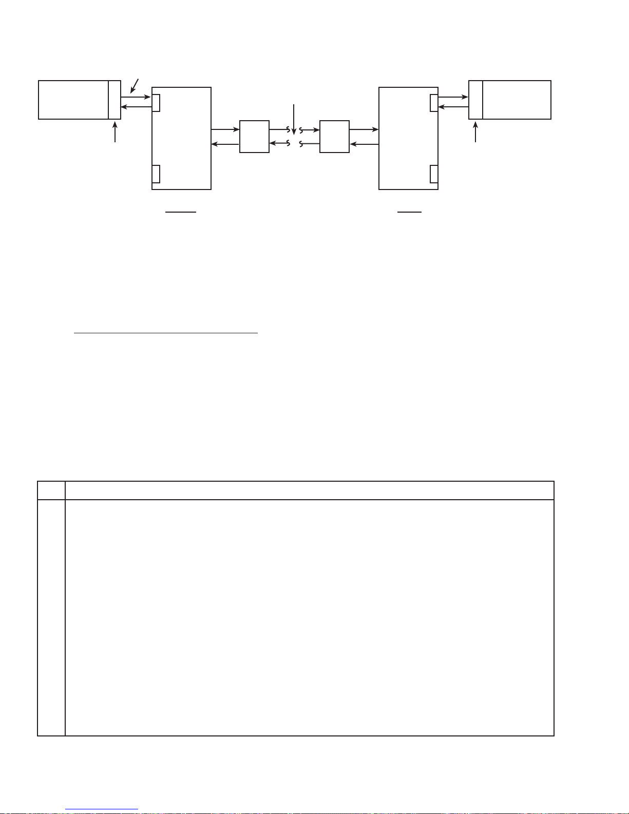
FIREBERD
#1
256 kb/s
Multichannel
Network
FIREBERD
#2
Multiplexer
RS449/530/MIL
Near End
CSU CSU
Figure 6-3
Testing Near- and Far-End Subrate Equipment Simultaneously
6.2.5 End-to-End Synchronous Test Set-Up
Table 6-2 describes the FIREBERD 6000 set-up procedures for the bit error rate test illustrated in Figure 6-3.
Although these procedures specifically apply to the testing of
Multiplexer
RS449/530/MIL
Far End
9500406-00
modems and multiplexers using the RS-449 connector, you
can use them to set up any basic synchronous test using the RS449/530/MIL Interface.
Table 6-2
FIREBERD 6000 Synchronous Test Set-Up With RS-449
Step Activity
1. With the power to the FIREBERD 6000 turned off, insert the RS-449/530/MIL Data Interface in the designated rearpanel slot.
2. Press the POWER switch to apply power to the FIREBERD 6000.
RESULT: The SETUP display shows the units current configuration.
NOTE: If the FIREBERD 6000 is in Self-Loop mode after power-up, disengage the SELF LOOP switch.
3. Set the DATA switch to either the 511 or the 2047 data pattern if transmitting test data to either the local modem or
the remote modem. If testing a 256 kb/s subrate channel as shown in Figure 6-3 it is recommended to select 511 or 2047
as the data pattern.
4. Set the GEN CLK switch to the INTF position to receive the clock from the DCE.
5. Set the TIMING MODE switch to the SYNC position.
6. Set the MENU switch to the INTF SETUP position. Configure the RS449/530/MIL Data Interface as follows:
46
TELECOMMUNICATIONS TECHNIQUES CORPORATION
Page 53
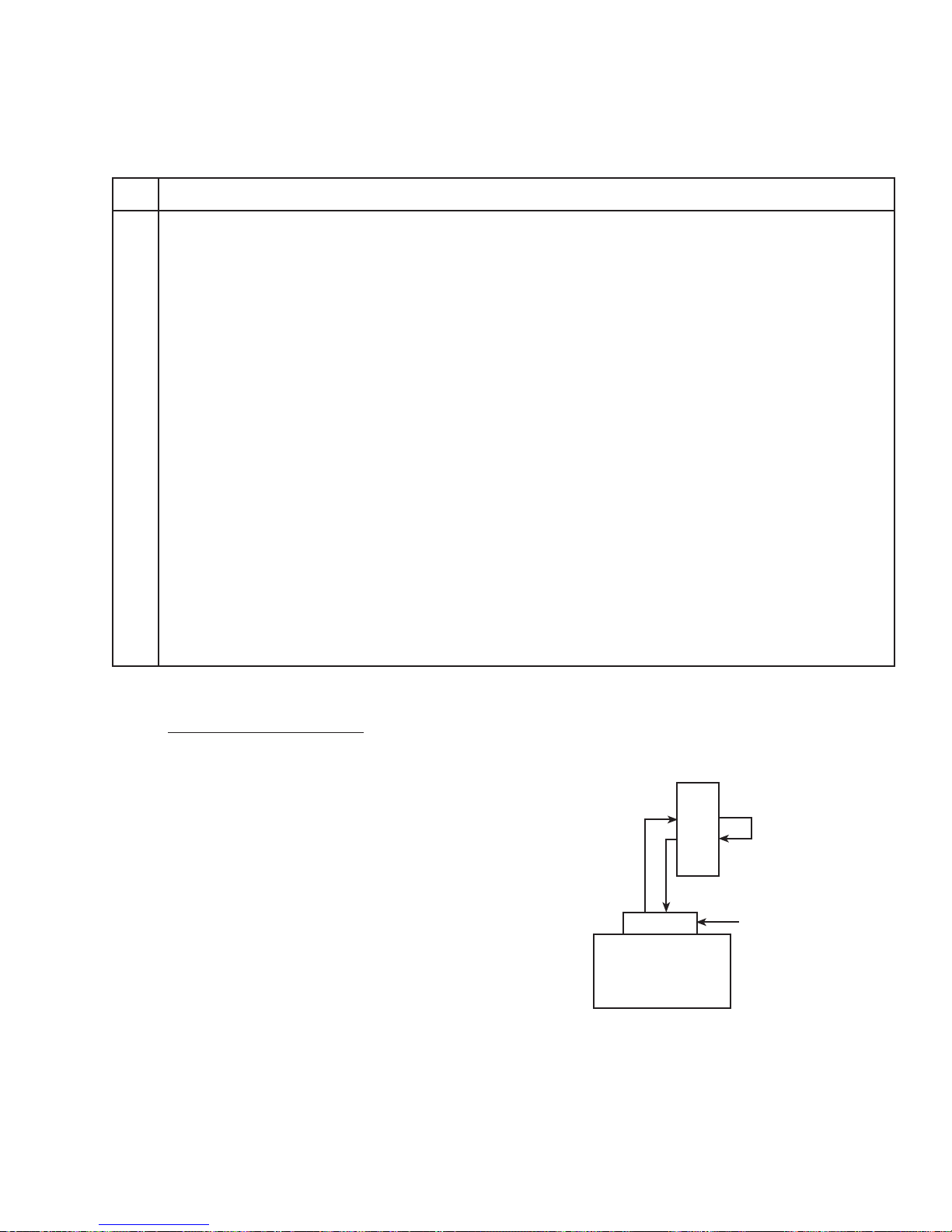
Table 6-2
FIREBERD 6000 Synchronous Test Set-Up With RS-449 (Continued)
Step Activity
Select
1. MIL449 to select the RS-449/530/MIL Interface.
2. RS449 to select the type of interface.
3. EMULATE to select DTE emulation.
4. SIGnaling to POSitive.
5. LL (Local Loop) and RL (Remote Loopback) ON or OFF depending on the test.
6. Press the up arrow on the MENU keypad.
7. MODE to select the mode menu.
8. BAL for balanced mode.
9. IMPEDANCE as required (78, 100, 124, or UNTERM) as required.
7. If hard copy test results are desired, set the print event criteria using PRINT EVENT, then enable the printer control
block (located to the left of the POWER switch) by setting the OFF/ON switch to the ON position.
8. Connect the FIREBERD 6000 to the equipment under test using the appropriate cables.
9. Illuminate the RTS and DTR switches located just above the POWER switch to set both signaling leads to HIGH.
12. If performing a looopback test, establish a loop by performing the procedures which are appropriate for your DCE.
10. Check that the SYNC LED located at the upper right-hand corner of the FIREBERD 6000 is illuminated.
RESULT: The FIREBERD has achieved pattern synchronization, and is gathering test results.
6.2.6 Synchronous Test Results
9600
Table 6-3 lists the significant synchronous test results that
b/s
are available with the RS449/MIL Data Interface. These
results can be collected via printer or can be viewed in the
RESULTS ANALYSIS display windows.
Modem 1
Loopback
6.3 ASYNCHRONOUS TESTING
6.3.1 Testing a 1200 b/s Asynchronous Modem
(Local Loopback)
Figure 6-4 shows a FIREBERD 6000 equipped with the
RS-449/530/MIL Interface. The instrument is connected to a
1200 b/s modem which has its output looped back to its own
input. The FIREBERD 6000 both transmits the test data and
analyzes the received data for errors.
FIREBERD
RS449/530/MIL
9500407-00
TELECOMMUNICATIONS TECHNIQUES CORPORATION
Figure 6-4
Testing an Asynchronous Modem
47
Page 54
Table 6-3
FIREBERD 6000 Synchronous Test Results
Category Results
ERROR AVG BER
AVG BLER
BER
BIT ERRS
BLOCKS
BLK ERRS
PAT SLIP
PERFORMANCE G ERR SEC
G EFS
G %EFS
DEG MIN
%DEG MIN
SES
%SES
UNA SEC
AVL SEC
%AVL SEC
BER-SES
ERR-SES
TIME ERR EAS
EA SEC
EF SEC
ELAP SEC
TIME
DATE
SIGNAL DELAY
RCV FREQ
GEN FREQ
ALARM PAT LOSS
DAT LOSS
CLK LOSS
C-D CHA
PWR LOSS
48
TELECOMMUNICATIONS TECHNIQUES CORPORATION
Page 55

Table 6-4
FIREBERD 6000 Asynchronous Test Set-Up With 188C
Step Activity
1. With the power to the FIREBERD 6000 turned OFF, insert the RS-449/530/MIL Data Interface in the designated rearpanel slot.
2. Press the POWER switch to apply power to the FIREBERD 6000.
RESULT: The SETUP display shows the units current configuration.
NOTE: If the FIREBERD 6000 is in Self-Loop mode after power-up, disengage the SELF LOOP switch.
3. Set the DATA switch to the FOX data pattern.
4. Set the GEN CLK switch to the SYNTH position for the FIREBERD to generate the clock.
5. Set the TIMING MODE switch to the ASYNC position.
6. Set the MENU switch to the SYNTH FREQ position. Set the synthesizer frequency to the desired baud rate.
7. Set the MENU switch to the INTF SETUP position. Configure the RS449/530/MIL Data Interface as follows:
Select
1. MIL449 to select the RS-449/530/MIL Interface.
2. 188C to select the type of interface.
3. EMULATE to select DTE emulation.
4. SIGnaling to POSitive.
5. LL (Local Loop) and RL (Remote Loopback) ON or OFF depending on the test.
8. Set the MENU switch to the CHAR FORMAT position. Select the desired asynchronous character format: DATA bits,
PARITY, and STOP bits.
9. If a timed test is desired:
1. Set the MENU switch to TEST INTERVAL.
2. Press the MORE key twice, then press the TIMED softkey.
3. set the desired test length using the MENU keypad, then press the ENTER key.
4. Set the ANALYSIS MODE switch (located to the right of the RESULTS area) to SINGLE.
10. If a continuous test is desired:
1. Set the MENU switch to TEST INTERVAL.
2. Set the desired measurement interval (default setting: 104), then press the ENTER key.
3. Set the ANALYSIS MODE switch (located to the right of the RESULTS area) to CONTINUOUS.
11. If hard copy test results are desired, set the print event criteria using PRINT EVENT, then enable the printer control
block (located to the left of the POWER switch) by setting the OFF/ON switch to the ON position.
12. Connect the FIREBERD 6000 to the equipment under test using the appropriate cables.
13. Illuminate the RTS and DTR switches located just above the POWER switch to set both signaling leads to HIGH.
14. If performing a loopback test, establish a loop by performing the procedures which are appropriate for your DCE.
15. Check that the SYNC LED located at the upper right-hand corner of the FIREBERD 6000 is illuminated.
RESULT: The FIREBERD has achieved pattern synchronization, and is gathering test results.
TELECOMMUNICATIONS TECHNIQUES CORPORATION
49
Page 56
6.3.2 Asynchronous Test Results
Table 6-5 lists the significant asynchronous test results that
are available with the RS449/MIL Data Interface. These
results can be collected via printer or can be viewed in the
RESULTS ANALYSIS display windows.
Table 6-5
FIREBERD 6000 Asynchronous Test Results
Category Results
ERROR BIT ERRS
AVG BER
BER
BLOCKS
BLK ERRS
AVG BLER
CHAR ERR
TIME DATE
ERR EAS
E A SEC
E F EAS
ELAP SEC
TIME
PATL SEC
%PAT SEC
Category Results
SIGNAL DELAY
GEN FREQ
ALARM DAT LOSS
PWR LOSS
PAT LOSS
PERFORMANCE GERR SEC
G EFS
G %EFS
DEG MIN
%DEG MIN
SES
%SES
UNA SEC
AVL SEC
%AVL SEC
PATL SEC
%PAT SEC
ERR-SES
BER-SES
50
TELECOMMUNICATIONS TECHNIQUES CORPORATION
Page 57

SECTION 7
INTERFACE SPECIFICATIONS
7.1 INTRODUCTION
This section contains the specifications for the RS-449/530/MIL Interface Adaptor. This information is listed in Table 7-1.
Table 7-1
RS-449/530/MIL Data Interface Specifications
Item Specification
Maximum Speed
MIL-188C 64 kb/s synchronous timing
20 kb/s asynchronous timing
64 kb/s recovered timing*
EIA 530, MIL-188-114, RS-449 Balanced 15 Mb/s synchronous timing
20 kb/s asynchronous timing
520 kb/s recovered timing*
EIA 530, MIL-188-114, RS-449 Unbalanced 128 kb/s synchronous timing
20 kb/s asynchronous timing
128 kb/s recovered*
Normal Data Polarity
MIL-188C MARK (binary “1”): “A” lead positive with respect to signal
ground.
SPACE (binary “0”): “A” lead negative with respect to
signal ground.
RS-423/MIL-188-114 UNBAL MARK (binary “1”): “A” lead negative with respect to signal
ground
EIA 530 UNBAL SPACE (binary “0”): “A” lead positive with respect to signal
ground
RS-423/MIL-188-114 BAL MARK (binary “1”): “A” lead negative with respect to”B”
lead.
EIA 530 BAL SPACE (binary “0”): “A” lead positive with respect to “B”
lead.
Normal Signal Polarity
(signal polarity may be inverted)
RS-422/MIL-188-114 BAL OFF: “A” lead negative with respect to “B” lead.
EIA 530 BAL ON: “A” lead positive with respect to”B” lead.
RS-423/MIL-188-114 UNBAL OFF: “A” lead negative with respect to signal ground.
EIA 530 UNBAL ON: “A” lead positive with respect to signal ground.
*FIREBERD 6000 with clock recovery option
TELECOMMUNICATIONS TECHNIQUES CORPORATION
51
Page 58
Table 7-1
RS-449/530/MIL Data Interface Specifications (Continued)
Item Specification
Unbalanced Drivers
Short circuit current 150 ma max
Output Level (Both states) 0.9Vo (into 450 Ohms)
Output rise time (clock drivers) 1.2 µs max
Output rise time (signaling drivers) 10 µs typical
Open circuit voltage (Vo) 5.5 + .5 volts
Balanced Drivers
Short circuit current 150 mA max
Differential output signal swing 2 volts min. (with a 100 ohm load)
Output rise and fall time 20 ns max.
Open circuit voltage 6 volts max.
Average DC offset 0V + 0.4 volts
Receivers
Termination resistance 78 ohms/100 ohms/124 ohms/unterminated
(specified with fail safe networks) (RCV DATA, RCV CLK, EXT TX CLK)
Input Impedance 7.4 k ohm minimum
Differential (between A and B)
6.6 k ohm minimum
Single ended A to ground with B grounded
Input threshold +0.2 volts (A versus B)
Operating Environment
Operating Temperature 0°C (+32°F) to 50°C (+124°F)
Relative Humidity 10% to 95% (non-condensing)
Storage Temperature -30°C (-22°F) to 75°C (+167°F)
Shock and Vibration
Shock Designed to IEEE 743-1985
Vibration Designed to IEEE 743-1985
EMI
Designed to good commercial practice
Dimensions 7.3" (185mm) wide, 1.5" (38mm) high, 5.23" (133mm) deep
Weight 13.6 ounces (386 grams)
52
TELECOMMUNICATIONS TECHNIQUES CORPORATION
Page 59

MAINTENANCE AND SERVICE
SECTION 8
8.1 INTRODUCTION
This section contains information on maintenance and
service for the RS-449/530/ MIL interface Adapter. It also
describes TTC’s warranty policies and repair procedures.
8.2 MAINTENANCE
8.2.1 In Case of Difficulty
If the unit fails to operate and no front panel indicators
illuminate, check the following:
• AC power cord and AC power supply
• AC fuse and fuse size
• Interface clock connection
If some indicators illuminate but the unit fails to operate,
verify that the interface in use is the correct type and is
properly inserted (turn off power before inserting or removing
interface). Check the interface cable and connections to the
FIREBERD. Try substituting another interface if one is
available.
Follow the self-test procedures in the FIREBERD Operating manual as an aid in localizing the problem. If the unit
continues to be inoperative, refer to the following sections for
service information or call the TTC Customer Service Department for applications assistance.
NOTE: Verify that the interface clock source is connected
before attempting self-test.
8.3 SERVICE
8.3.1 Warranty Policy
All equipment manufactured by TTC is warranted against
defects in material and workmanship. This warranty applies
only to the original purchaser and is non-transferable unless
express written authorization of the warranty transfer is granted
by TTC.
Liability under this warranty extends only to the replacement value of the equipment. The warranty is void if:
(1) Equipment has been altered or repaired without
specific authorization from TTC.
(2) Equipment is installed or operated other than in
accordance with instructions contained in TTC
literature and operating manuals.
No other warranty is expressed or implied. TTC is not
liable for consequential damages.
8.3.2 In-Warranty Service
Equipment in warranty must be returned to the factory
with shipping prepaid. The equipment should be packed and
shipping prepaid. The equipment should be packed and
shipped in accordance with the instructions in Section 8.3.4 of
this manual. Before returning any equipment, the customer
must obtain a Return Authorization (RA) number by contacting the TTC Instrument Service Center. The RA number
should then appear on all paperwork and be clearly marked on
the outside of the shipping container.
After the equipment is repaired by TTC, it will be tested
to applicable specifications, burned-in for at least 24 hours,
retested, and returned to the customer with shipping prepaid.
A brief description of the work performed and the materials
used will be provided on the Equipment Repair Report furnished with the returned equipment.
TELECOMMUNICATIONS TECHNIQUES CORPORATION
53
Page 60

8.3.3 Out-Of-Warranty Service
8.3.4 Equipment Return Instructions
The procedure for repairing out-of-warranty equipment
is the same as that used for equipment still in warranty.
However, there is a minimum charge applied to each
request for out-of-warranty service. The minimum charge
guarantees the customer an estimate of the repair costs and
used as credit against actual materials and labor costs should
the equipment be repaired. Contact the TTC Instrument
Service Center for specific information on the minimum outof-warranty repair charge.
The customer will be billed for parts plus standard labor
rates in effect at the time of repair. The customer will also be
required to furnish a purchase order number before repair
work can be started, and a hard copy of the purchase order
must be received by TTC before the repaired equipment may
be shipped to the customer. A description of the labor and
materials used will be provided in the Equipment Repair
Report.
Once an out-of-warranty repair is made, the repaired part
or component is warranted for 90 days. This warranty applies
only to the part or component that was repaired; other parts or
components are not covered under the 90-day repair warranty.
The customer should attach a tag to all equipment re-
turned for repair that includes the following information:
(1) Owner name and address.
(2) A list of equipment being returned and the appli-
cable serial number(s).
(3) A detailed description of the problem or service
requested.
(4) The name and telephone number of the person to
contact regarding questions about the repair.
(5) The Return Authorization (RA) number.
If possible, the customer should return the equipment
using the original shipping container and material. If the
original container is not available, the unit should be carefully
packed so that it will not be damaged in transit. TTC is not
liable for any damage that may occur during shipping. The
customer should clearly mark the TTC issued RA number on
the outside of the package and ship it prepaid and insured to
TTC.
54
TELECOMMUNICATIONS TECHNIQUES CORPORATION
Page 61
APPENDIX A
RS-449/530/MIL DATA INTERFACE FACTORY DEFAULTS
Table A-1
Data Interface Default Settings
Item Factory Default
TYPE RS449
CONNECTOR D-Type
EMULATE DTE
MODE BAL
IMPEDANCE 100 ohms
APPENDIX A
TIMING SYNC
DATA BITS 8
PARITY ODD
STOP BITS 1
RCV CLOCK AUTO
SIGNALING
TM OFF
CTS OFF
LL OFF
RL OFF
SIGNALING POS
TELECOMMUNICATIONS TECHNIQUES CORPORATION
55
Page 62

56
TELECOMMUNICATIONS TECHNIQUES CORPORATION
 Loading...