

Tsyklon Labs Plitka Trace Build Instructions
DIY Build Instructions – PLITKA TRACE (MINIATURE OSCILLOSCOPE)
First off, thank you for your purchase of the PLITKA TRACE DIY Kit. If you are a DIY Synth novice, you have selected a great module to
advance your skills. It is not as simple a circuit as the DISPRS or DIÔD OR, but still very doable. If you have built our BTN MASHR, you can
build this one. If you are a veteran (or, as we like to say at Tsyklon Labs - “Hero of Synthesizer DIY”), then this kit will be super fun.
First, let's make sure that you have everything on hand before we heat up the iron. The tools you will need are as follows:
- Soldering Iron and Solder
- Wire Cutters
- Wire Strippers
- Needle Nose Pliers
- Knurled Nut Tool (Xicon 382-0006) or Small Pliers for tightening 3.5mm knurled nuts
- 2.5mm Allen Key
- Adjustable Wrench or 5.5mm Nut Driver
- Lead Bending/Forming Tool (I like the Production Devices Model 801)
The following components have been provided in the PLITKA TRACE DIY Kit:
Quantity Part Description
1 Tsyklon Labs TRACE PCB
1 Tsyklon Labs TRACE Front Panel
2 M3 x 18mm Metric Black-Oxide Screw
2 M3 Locking Nut
2 M3 x 10mm Nylon Spacers
1 Futaba 3 wire servo cable with keyed J connector
DIY Build DOC/BOM PLITKA TRACE V 1.3 Page 1
Also, you will need the following parts to finish your build:
Qty Part Description PCB Component ID Part Number Vendor
1 0.33uF 50V Electrolytic Capacitor C101 647-UFG1HR33MDM Mouser
1 0.15uF 50V Electrolytic Capacitor C102 647-UKL1HR15KDDANA Mouser
1 Reverse Power Protection Diode D101 512-1N4001 Mouser
1 5VDC Regulator, 100mA, TO-92 REG_5V 512-LM78L05ACZ Mouser
2 10-pin, 2x5, 2.54mm Pitch Pin Hdr POWER, HDR_LOGIC_IN 571-5-146256-5 Mouser
1 Mini Oscilloscope Xprotolab Xprotolab Gabotronics.com
4 3.5mm Jacks CH1, CH2, EXT_TRG, AWG 3.5mm Inline Jacks Erthenvar
4 3.5mm Nuts CH1, CH2, EXT_TRG, AWG 3.5mm Knurled Nuts Erthenvar
Now that we have that out of the way, let us start the module build!
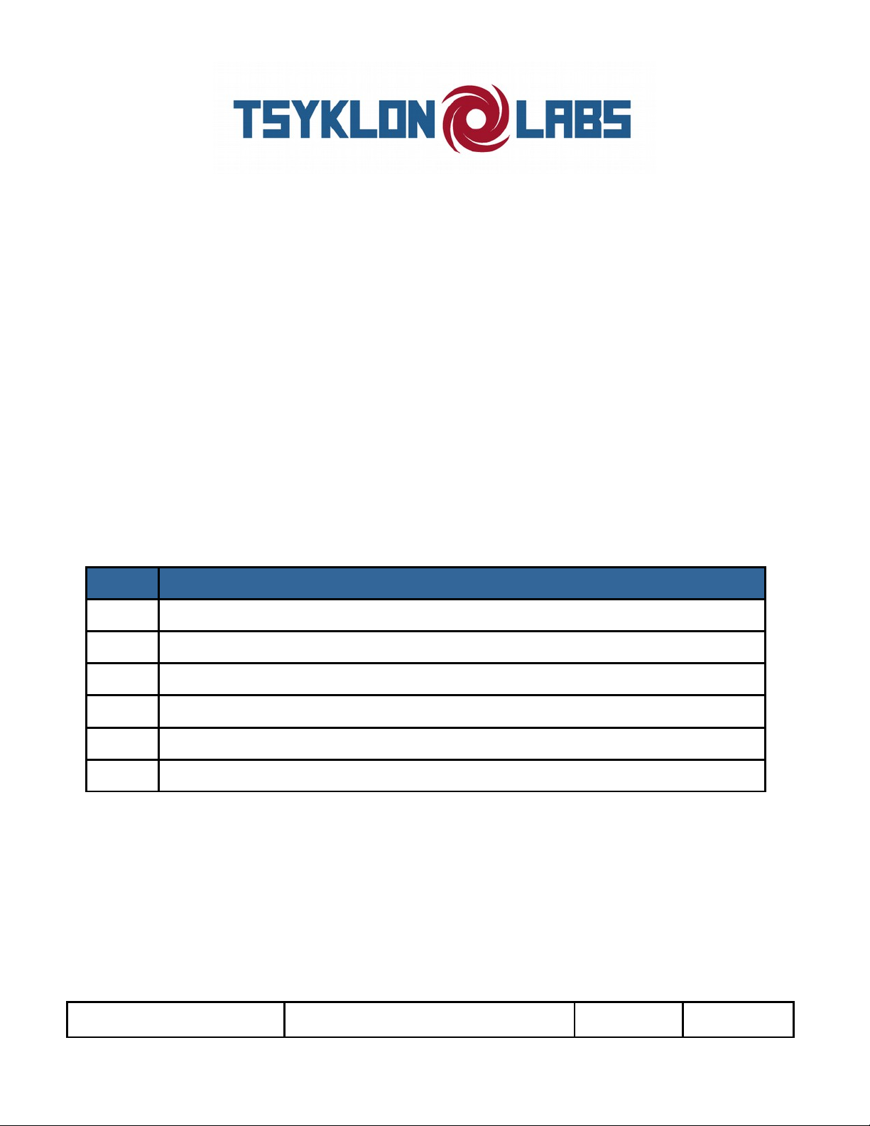
1) Take a look at the PCB and Front Panel. This is the top/front side of each:
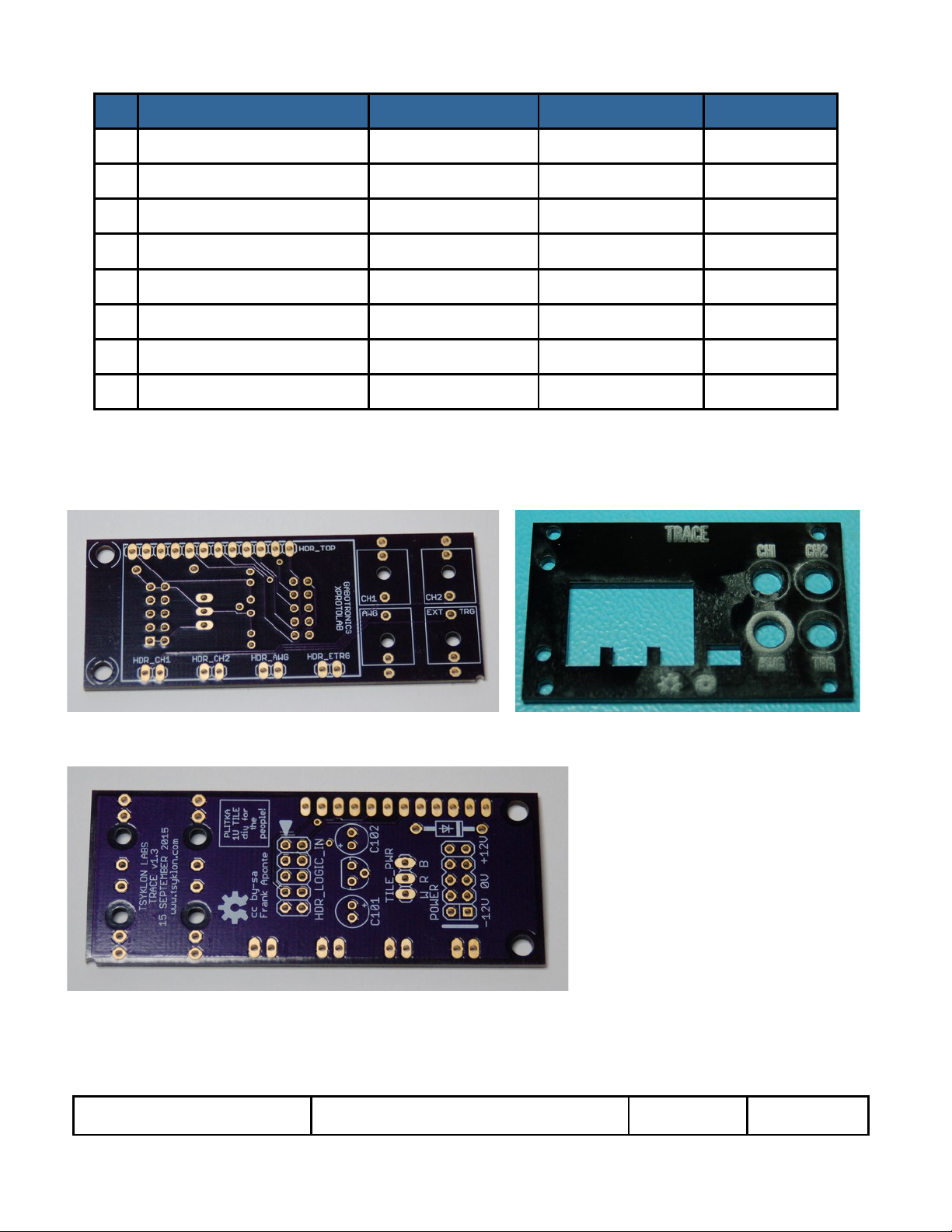
2) And the reverse/back side of the PCB:
DIY Build DOC/BOM PLITKA TRACE V 1.3 Page 2

3) Start by painting the front of the Front Panel (if you want to). Smearing in some acrylic paint with a stiff brush works well. LEAVE the
protective tape on so that there will be less clean up later. If you haven't done this before, please watch this video (65 seconds well
invested). Better information in the video than I can convey here with words:
https://vimeo.com/54711135
4) Once you have painted the panel, and the paint has dried, peel off the protective tape (again, good example in the video). Your panel
should look something like this. You may need to use a little bit of isopropyl alcohol and a piece of paper towel to clean up the side edges
of the panel.
5) Start stuffing the PCB with the 5VDC Voltage Regulator IC. It looks like a small transistor with three legs. Insert it through the Back
side of the PCB keeping the flat part of the IC lined up with the flat part of the PCB silkscreen as shown below. When soldering, get
enough heat on the pin you are soldering to make a good solder joint without overdoing the heat to the component. It is a good idea to
give the IC a few minutes to cool down between pins. Another option is to combine this step with the next few steps – this will let you
solder one pin on the IC, then solder one pin on each of the diode and capacitors, then solder another IC pin, then the rest of the other
component's pins, then come back for the last IC pin.
DIY Build DOC/BOM PLITKA TRACE V 1.3 Page 3
 Loading...