

Tsurumi Pump TPG4-3000HDX Operation, Service And Repair Manual

Tsurumi’s Operation, Service, and Repair Manual
Introduction
3
WARNING: THIS GENERATOR IS DESIGNED TO GIVE SAFE AND DEPENDABLE SERVICE WHEN
OPERATED ACCORDING TO THE INSTRUCTIONS IN THE TECHNICAL MANUALS PROVIDED
WITH THE GENERATOR.
WARNING: DO NOT OPERATE THE GENERATOR BEFORE YOU HAVE READ AND UNDERSTAND THE
INSTRUCTIONS AND THE ENGINE MANUFACTURER’S MANUAL. FAILURE TO DO SO
COULD RESULT IN PERSONAL INJURY OR EQUIPMENT DAMAGE.
1-3 Placards
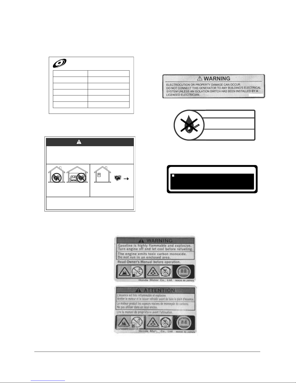
Placards, shown in Figure 1-1 through Figure 1-8 are attached to the portable generator to warn
operating and maintenance personnel of potential hazards, to provide maintenance information,
and to provide generator ratings and capabilities. The large label below is located on the front
panel of the portable generator. The label presents operational Warnings and Cautions for
generator users.
1-4 SAFETY PRECAUTIONS
WARNING: IN ORDER TO ASSURE SAFE AND EFFICIENT OPERATION OF THE GENERATOR,
OPERATOR’S SHOULD READ AND COMPLY WITH THE FOLLOWING SAFETY PRECAUTIONS.
• Do not operate the generator near gasoline or gaseous fuels because of the potential danger from
explosion or fire. Do not fill the fuel tank with fuel while the engine is running. Do not smoke or use open flame
near the fuel tank. Be careful not to spill fuel during refueling. If fuel is spilled, wipe it off and let it dry before
starting the engine.
• Do not place flammable materials near the generator. Be careful not to place fuel, matches, gunpowder, oily
cloths, straw, trash, or any other combustibles near the generator.
• Do not operate the generator inside a room, cave, tunnel, or other insufficiently ventilated area. Always
operate the generator in a well-ventilated area. The engine may become overheated, and the poisonous carbon
monoxide gas contained in the exhaust gases will endanger human lives.
• Keep the generator at least 1 meter (3 feet) away from any structure or building during use. When a
generator is located close to a building or nearby equipment, heat and exhaust from the engine will cause the
surrounding temperature to rise. This will degrade the engines cooling efficiency, causing overheating.
• Do not enclose the generator nor cover it with a box. The generator has a built-in, forced-air cooling system,
and may become overheated if it is enclosed.
• Operate the generator on a level surface. It is not necessary to prepare a special foundation for the generator.
However, the generator will vibrate on an irregular surface. Therefore, choose a level place without surface
irregularities.
• Shutoff the generator when moving the generator to another work site. It the generator is tilted or moved
during operation, fuel may spill and/or the generator may tip over, causing a hazardous situation. Proper
lubrication cannot be expected if the generator is operated on a steep incline or slope. In such a case, the piston
may seize; it may seize even if the oil is above the upper level.
• Do not operate in rain or with wet hands. The operator may suffer severe electric shock, if the generator is wet
due to rain or snow. If wet, dry before starting. Do not pour water directly over the generator, nor wash it with water.
• Do not connect the generator to a commercial power line. Connection to a commercial power line may result
in short circuit and damage the generator. When connecting to domestic circuits, install only approved transfer
switches and make sure power and control circuitry meet local electrical code requirements.
• Do not smoke or use other smoking materials (pipes, cigars, etc.) while handling the battery. The battery
emits flammable hydrogen gas, which can explode if exposed to electrical arcing or open flame. Keep the work
area well ventilated and keep the battery away from open flames/sparks.
Tsurumi’s Operation, Service, and Repair Manual
Introduction
3
MADE IN JAPAN
MODEL
RATED OUTPUT
FREQUENCY
VOLTAGE
MAX. OUTPUT
60Hz
SERIAL NO.
******
120V
2.2kVA
2.6kVA
TPG4-3000HDX
TSURUMI PORTABLE GENERATOR
TPG4 Fig. 1-1
Using a generator indoors CAN KILL YOU IN MINUTES.
Genera tor exhaust contains carbon monoxide. This is
a poison y ou cannot see or smell.
Avoid other generator hazards.
READ MANUAL BEFORE USE.
DANGER
NEVER use inside a home
or garage, EVEN IF doors
and windows are open.
Only use OUTSIDE and
far away from windows,
doors, and vents.
TPG4 Fig. 1-3
AIR CLEANER MAINTENANCE
CLEAN ELEMENT EVERY 50 HOURS (EVERY
10 HOURS UNDER DUSTY CONDITIONS).
WASH IN HIGH FLASH-POINT SOLVENT,
SQUEEZE DRY,THEN DIP IN CLEAN ENGINE
OIL AND SQUEEZE OUT EXCESS OIL.
TPG4 Tig. 1-5
■CHECK FOR SPILLED FUEL O R FUEL LEAKS.
STOP ENGINE BEFORE REFUELING.
■INSPECCIONAR PARA CO MBUSTIBLE DERRAMA DO
O ESCAPE.
PARAR MOTOR A NTES DE ECHAR.
■CONTROLER QU’
REPANDUE SUR L’
ARRETER LE MOTEUR AVANT DE REFAIRE LE PLEIN.
IL N’Y A NI FUITE NI ESSENCE
APPAREIL
^
^
´
TPG4 Fig 1-4
TPG4 Fig. 1-6
TPG4 Fig. 1-2
Figure 1-1: Typical Data Plate
Figure 1-3: Carbon Monoxide Warning
Figure 1-2: Electrical Warning
Figure 1-4: Fuel Handling Warning
Figure 1-5: Air Cleaner Maintenance Warning
Figure 1-6: Gasoline/Carbon Monoxide Warning

Tsurumi’s Operation, Service, and Repair Manual
Operating Instructions
13
3-0 OPERATING INSTRUCTIONS
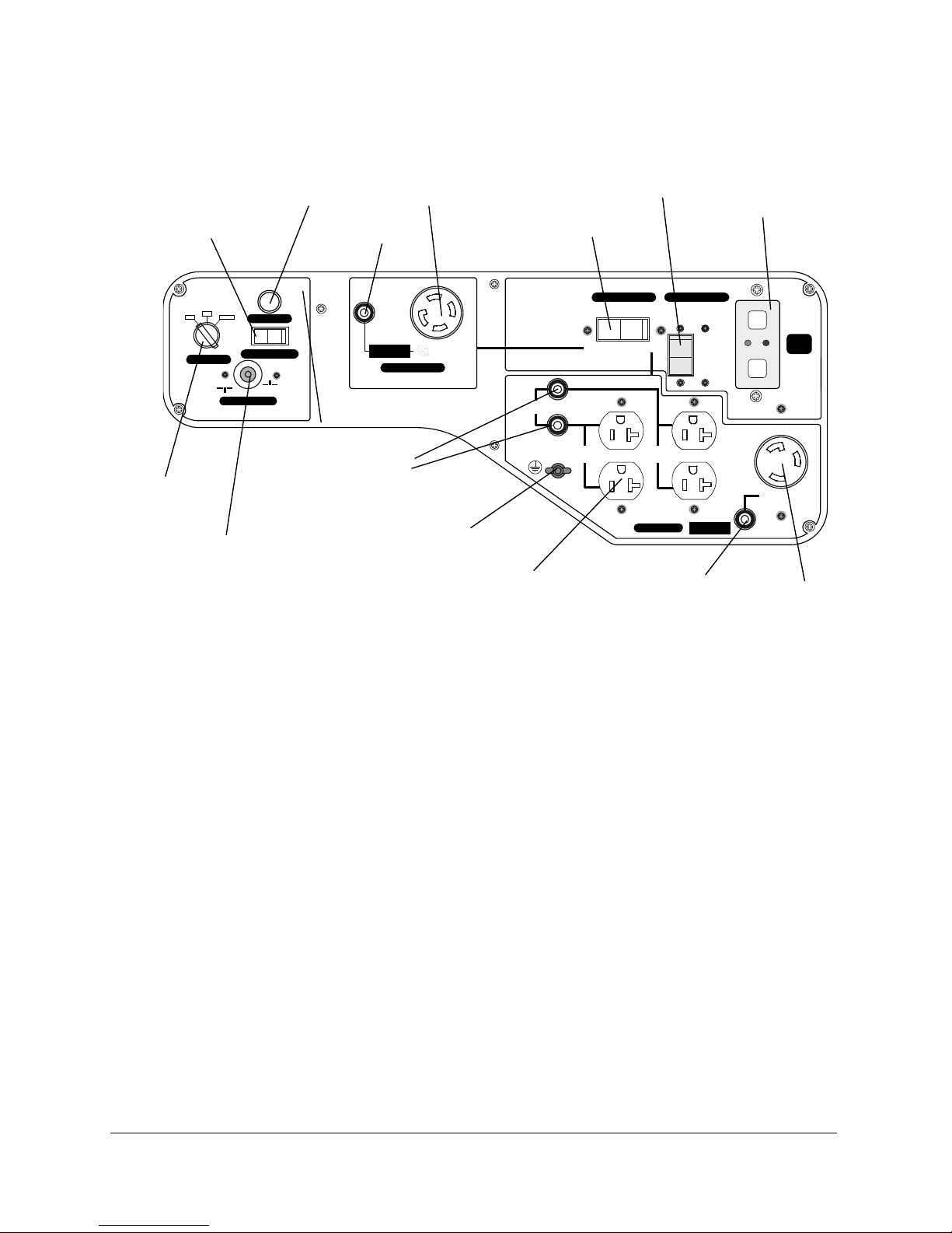
3-1 Operating Controls
(1) The main operating controls for the generator are, with a few exceptions, mounted on the
front panel of the generator.
(2) The controls consist of an ENGINE switch, an AUTOTHROTTLE switch, a FULL POWER
switch, a PILOT light, circuit BREAKER(s), a ground (or earth) post, and electrical
receptacles. The specific controls used in each model are shown in Figures 3-1 through
3-4.
NOTE: The auto throttle feature is not available on Model TPG4-3000HDX, which uses a
hand operated throttle lever.
(3) The Model TPG4-7000H-DXE generator is equipped with a electric starter motor. The
ENGINE switch in this model is a key-operated, STOP/RUN/START switch. The springloaded switch is turned to the right to start the engine, and to the left to shut off the
engine.
(4) The IDLE Control switch allows the generator speed to drop to idle speed if there is no
electrical load demand on the generator. When an electrical load is sensed, the idle
function increases the speed of the generator up to operating speed level. When there is
no load, the engine speed returns to idle.
(5) The FULL POWER switch allows the generator to provide full rated power for the loading
appliances and/or tools. When the FULL POWER switch is set to on, power will be
provided to only one 120 Vac receptacle and one 240 Vac receptacle.
(6) The PILOT light provides an indication to the operator that the generator is generating
electricity.
(7) Circuit breakers are provided to protect the generator in the event of a short circuit. The
breakers will trip when the circuit load exceeds the breaker’s rated value.
(8) The ground post is used to provide a positive ground for the generator. The post has a
wing-nut to quickly connect a ground wire to the generator.
(9) There are three types of receptacles: one 120 Vac, GFI-protected receptacles (two on
most models), one twist-type, 120 Vac receptacle, and one 120 Vac / 240 Vac,
combination receptacle.
3-2 DC Circuit Controls
(1) The circuitry for DC circuit consists of a 10 Amp fuse, an overload protector, and a reset
switch. (Model TPG4-7000HDXE only.)
(2) In the event of an overload, the overload protector will trip the reset switch located
immediately below the engine key starter switch.
Tsurumi’s Operation, Service, and Repair Manual
Operating Instructions
15
IDLE CONTROL SW.
PILOT
AT 120/240V
AT 120V ONLY
AC 120V/240V
VOLTAGE SELE CTOR CIRCUIT BRE AKER
GFCI
SW.
ON
120V ONLY
OFF
AC 120V
ON
OFF
TOTAL
20A
TOTA L
20A
30A
120V/240V
CIRCUIT BREAKER
PRESS TO RES ET
CIRCUIT BREAKER
PRESS TO RES ET
CIRCUIT BREAKER
PRESS TO RES ET
OFF
O N
START
ENGINE SW.
STARTER RESET SW.
ON/P USH
OFF
TEST
TEST
RESET
RESET
Figure 3-3: Model TPG4444-7000HDXE
Starter reset
switch
Voltage selector
Receptacle 120V
Receptacle 120/240V
Idle control switch
Engine switch
Pilot
lamp
Circuit breaker
GFCI switch
Circuit breaker
30A
Circuit breaker
30A
Ground terminal
Circuit breaker
20A
Receptacle 120V

Tsurumi’s Operation, Service, and Repair Manual
Operating Instructions
16
3-3 Grounding Provisions
WARNING: TO PREVENT ELECTRICAL SHOCK FROM FAULTY APPLIANCES, THE PORTABLE
GENERATOR SHOULD BE GROUNDED. CONNECT A LENGTH OF HEAVY WIRE
BETWEEN THE GENERATOR’S GROUND TERMINAL AND EXTERNAL GROUND
SOURCE.
WARNING: CONNECTIONS FOR STANDBY POWER TO A BUILDING’S ELECTRICAL SYSTEM MUST
BE MADE BY A QUALIFIED ELECTRICIAN AND MUST COMPLY WITH ALL APPLICABLE
LAWS AND ELECTRICAL CODES. IMPROPER CONNECTIONS CAN ALLOW
ELECTRICAL CURRENT FROM THE GENERATOR TO BACKFEED INTO THE UTILITY
LINES. SUCH BACKFEED MAY ELECTROCUTE UTILITY COMPANY WORKERS OR
OTHERS WHO CONTACT THE LINES DURING A POWER OUTAGE, AND WHEN UTILITY
POWER IS RESTORED, THE GENERATOR MAY EXPLODE, BURN, OR CAUSE FIRES IN
THE BUILDING’S ELECTRICAL SYSTEM.
A. Electrical Connection Hazards
(1) If you plan to use the portable generator as a backup for the facility’s power supply, make
sure the connections are made in compliance with applicable laws and electrical codes.
(1) Connection to a building’s electrical system must be made by a qualified electrician.
(2) Improper connections can allow electrical current from the generator to backfeed into the
utility lines which may electrocute utility company workers or others who contact the lines
during a power outage. When utility power is restored, the generator may explode, burn,
or cause fires in the building’s electrical system.
B. Grounding Post Components
(1) The portable generator is fitted with a grounding post on the right side of the control panel.
The parts that make up the grounding post are shown in the Replacement Parts section.
The grounding post components and their installation sequence are shown in more detail
in Figure 3-4.
(2) If the grounding post has been disassembled, reassemble as follows:
(a) Install star washer (68) on screw (69). Insert screw (69) in backside of panel (46).
(b) Install nut (69) on screw (69) and tighten.
(c) Install cup washer (70) with sides facing out.
(d) Install flat washer (71), lock washer (72), and wing nut (73).
C. Typical Connection of Ground Wire
(3) Form a loop in ground wire and slip wire between flat washer (71) and cup washer (70).
Tighten wing nut (73).
(4) Drive ground rod in ground (or attach to known facility ground). Insert free end of ground
wire in clamping screw on rod (or other clamping device) and tighten.
 Loading...