

Tsurumi Pump TE3 Series, TE3-50HA, TE3-100HA, TE3-80HA Operation, Service And Repair Manual
OPERATION, SERVICE, AND
REPAIR MANUAL
FOR TSURUMI TE3-SERIES
CENTRIFUGAL PUMPS
MODELS
TE3-50HA
TE3-80HA
TE3-100HA

LIMITED WARRANTY
TSURUMI MANUFACTURING CO., LTD. (“TSURUMI”) warrants to the original end purchaser during
the warranty period, every new TSURUMI pump or product to be free from defects in material and
workmanship under normal use and service, when properly installed, used, and maintained (in accordance with Tsurumi’s Operation, Service, and Repair Manual) for a period of two years from the date
the unit was first installed or twenty six months from the date of shipment by TSURUMI to wholesaler,
whichever comes first.
TSURUMI’S sole obligation under this warranty is to repair or replace at TSURUMI’S option, with new
or remanufactured parts, any part(s) that fail or that are found to be defective during the warranty period. No allowance will be made for shipping charges, damages, labor, or other charges due to failure,
repair or replacement.
This warranty does not apply to any TSURUMI product that has been disassembled without prior
approval of TSURUMI nor does it apply to any product that has been subjected to misuse, neglect,
alteration, misapplication, accident or act of God.
TSURUMI assumes no responsibility for compliance with any regulations, codes, standards, or ordinances applicable to the installation, location, operation or maintenance of its products.
No other warranty, expressed or implied, is authorized by, or applicable to, the seller. No person, agent
or dealer is authorized to enlarge upon this warranty.
TSURUMI expressly disclaims liability for consequential or incidental damages or breach of expressed
or implied warranty; and any implied warrant of fitness for a particular purpose and merchantability
shall be limited to the duration of the expressed warranty.
Some states do not allow limitations on the duration of an implied warranty, so the above limitation or
exclusion may not apply to you. Some states do not allow the exclusion or limitation of incidental or
consequential damages, so the above limitation of exclusion may not apply to you.
This warranty gives you specific legal rights and you may also have other rights, which vary from state
to state.
Tsurumi Manufacturing Co., Ltd.

TABLE OF CONTENTS
Section/Title Page
1. Introduction . . . . . . . . . . . . . . . . . . . . . . . . . . . . . . . . . . . . . . . . . . . . . . . . . . . . . . 1
1-1. Using Your Tsurumi Operation, Repair and Service Manual . . . . . . . . . . . . . 1
1-2. Precautions . . . . . . . . . . . . . . . . . . . . . . . . . . . . . . . . . . . . . . . . . . . . . . . . . 1
1-3. Safety Precautions . . . . . . . . . . . . . . . . . . . . . . . . . . . . . . . . . . . . . . . . . . . 2
1-4. Specifications / Key Features . . . . . . . . . . . . . . . . . . . . . . . . . . . . . . . . . . . . 3
1-5. Performance Curves. . . . . . . . . . . . . . . . . . . . . . . . . . . . . . . . . . . . . . . . . . . 3
2. Operating Instructions . . . . . . . . . . . . . . . . . . . . . . . . . . . . . . . . . . . . . . . . . . . . . . . 6
2-1. Operating Controls . . . . . . . . . . . . . . . . . . . . . . . . . . . . . . . . . . . . . . . . . . . 6
2-2. Check the Engine Oil Level . . . . . . . . . . . . . . . . . . . . . . . . . . . . . . . . . . . . . 6
2-3. Check Engine Fuel . . . . . . . . . . . . . . . . . . . . . . . . . . . . . . . . . . . . . . . . . . . 8
2-4. Check Fuel Level . . . . . . . . . . . . . . . . . . . . . . . . . . . . . . . . . . . . . . . . . . . . . 8
2-5. Pre-Start Checks . . . . . . . . . . . . . . . . . . . . . . . . . . . . . . . . . . . . . . . . . . . . . 9
2-6. Starting and Operating the Engine . . . . . . . . . . . . . . . . . . . . . . . . . . . . . . . . 9
2-7. Using the Centrifugal Pump . . . . . . . . . . . . . . . . . . . . . . . . . . . . . . . . . . . . . 10
2-8. Stopping the Centrifugal Pump . . . . . . . . . . . . . . . . . . . . . . . . . . . . . . . . . . 10
2-9. Oil Alert . . . . . . . . . . . . . . . . . . . . . . . . . . . . . . . . . . . . . . . . . . . . . . . . . . . . 10
3. Troubleshooting . . . . . . . . . . . . . . . . . . . . . . . . . . . . . . . . . . . . . . . . . . . . . . . . . . . 11
3-1. Troubleshooting Charts . . . . . . . . . . . . . . . . . . . . . . . . . . . . . . . . . . . . . . . . 11
4. Maintenance . . . . . . . . . . . . . . . . . . . . . . . . . . . . . . . . . . . . . . . . . . . . . . . . . . . . . . 12
4-1. Maintenance Schedule . . . . . . . . . . . . . . . . . . . . . . . . . . . . . . . . . . . . . . . . . 12
4-2. Changing Engine Oil . . . . . . . . . . . . . . . . . . . . . . . . . . . . . . . . . . . . . . . . . . 13
4-3. Air Cleaner Service . . . . . . . . . . . . . . . . . . . . . . . . . . . . . . . . . . . . . . . . . . . 14
4-4. Sediment Cup Cleaning . . . . . . . . . . . . . . . . . . . . . . . . . . . . . . . . . . . . . . . . 14
4-5. Cleaning and Adjusting Spark Plug. . . . . . . . . . . . . . . . . . . . . . . . . . . . . . . . 14
4-6. Disassembly of Centrifugal Pump . . . . . . . . . . . . . . . . . . . . . . . . . . . . . . . . . 15
4-7. Replacement of Mechanical Seal . . . . . . . . . . . . . . . . . . . . . . . . . . . . . . . . . 17
4-8 Removal and Installation of Engine. . . . . . . . . . . . . . . . . . . . . . . . . . . . . . . . 20
4-9 Replacement of Cushions . . . . . . . . . . . . . . . . . . . . . . . . . . . . . . . . . . . . . . 20
4-10. Assembly of Centrifugal Pump . . . . . . . . . . . . . . . . . . . . . . . . . . . . . . . . . . . 22
4-11. Replacing of Check Valve . . . . . . . . . . . . . . . . . . . . . . . . . . . . . . . . . . . . . . 23
5. Storage Instructions. . . . . . . . . . . . . . . . . . . . . . . . . . . . . . . . . . . . . . . . . . . . . . . . . 24
5-1. Procedures for Storing Pump . . . . . . . . . . . . . . . . . . . . . . . . . . . . . . . . . . . . 24
6. Replacement Parts . . . . . . . . . . . . . . . . . . . . . . . . . . . . . . . . . . . . . . . . . . . . . . . . . 25
6-1. Introduction . . . . . . . . . . . . . . . . . . . . . . . . . . . . . . . . . . . . . . . . . . . . . . . . . 25
6-2. Ordering Parts . . . . . . . . . . . . . . . . . . . . . . . . . . . . . . . . . . . . . . . . . . . . . . . 25
26/27
28/29
30/31
Exploded View/Parts Listing Exploded View/Parts Listing Exploded View/Parts Listing -
TE3-50HA . . . . . . . . . . . . . . . . . . . . . . . . . . .
TE3-80HA . . . . . . . . . . . . . . . . . . . . . . . . . . .
TE3-100HA . . . . . . . . . . . . . . . . . . . . . . . . . .

INTRODUCTION
1-1 Using Your Tsurumi Operation, Repair and Service Manual
We thank you for purchasing a Tsurumi centrifugal pump. We are sure that the centrifugal pump you
have selected will meet your portable pumping needs.
This manual applies to the Tsurumi centrifugal pumps listed below. Specifications for the centrifugal
pumps are provided in the SPECIFICATIONS section. Key features of the centrifugal pump are shown
in the DESCRIPTION section.
This manual provides instructions for operation, service, and repair of your centrifugal pump. We
strongly recommend that those who operate the centrifugal pump become familiar with the centrifugal
pump’s features and controls, and read the operating instructions before using the centrifugal pump.
The Operation, Repair, and Service Manual provides instructions to service, checkout, and repair the
centrifugal pump. This manual also provides replacement parts information.
Repair and service information for the Honda engine is provided in the Owner’s Manual for Models
GX160, GX240, and GX340. A copy of the Owner’s Manual has been provided in the centrifugal pump’s
literature package. Parts information for the Honda Engine is available in Honda’s Parts Catalogs.
When there are differences between centrifugal pump models, separate instructions are provided. The
separate instructions are provided to make sure the correct procedures are used on the affected centrifugal pumps.
All information in the Tsurumi manuals is based upon the latest production configuration of the centrifugal pump at the time of printing.
If you have a problem with your centrifugal pump that cannot be resolved using the Operation, Repair,
and Service Manual, or if you have questions about the operation, service, repair, or maintenance of
your centrifugal pump, contact your local Tsurumi centrifugal pump dealer.
1-2 Precautions
Pay special attention to precautionary notes preceded by the words WARNING,CAUTION, and NOTE.
W
ARNINGS indicate that there is a strong possibility of personal injury or loss of life if the procedure
is not followed, or if cleaning, lubricating, adhesives, and other materials are not used properly.
CA
UTIONS indicate that there is a possibility of equipment damage if instructions are not followed.
NO
TES are used in procedures to provide additional or supplemental information to make the proce-
dure easier or more efficient.
W
ARNING:
• The centrifugal pump is designed to give safe and dependable service when operated accord-
ing to the instructions in the technical manual provided with the centrifugal pump.
Introduction Page 1
Tsurumi’s Operation, Service, and Repair Manual
TE
3-50HA
TE
3-80HA
TE
3-100HA

• Do not operate the centrifugal pump before you have read and understand the instructions
and the engine manufacturer’s manual. Failure to do so could result in personal injury or
equipment damage.
1-3 Safety Precautions
WARNING:
• IN ORDER TO ASSURE SAFE AND EFFICIENT OPERATION OF THE CENTRIFUGAL PUMP,
OPERATORS SHOULD READ AND COMPLY WITH THE FOLLOWING SAFETY PRECAUTIONS.
• Do not operate the centrifugal pump near gasoline or gaseous fuels because of the poten-
tial danger from explosion or fire.
• Do not fill the fuel tank with fuel while the engine is running. Be careful not to spill fuel during
refueling. If fuel is spilled, wipe it off and let it dry before starting the engine.
• Do not smoke or use an open flame near the fuel tank.
• Do not place flammable materials near the centrifugal pump. Be careful not to place fuel,
matches, gunpowder, oily cloths, straw, or any other combustibles near the centrifugal pump.
• Do not operate the centrifugal pump inside a room, cave, tunnel, or other insufficiently ven-
tilated area. Always operate the centrifugal pump in a well-ventilated area. The engine may
become overheated, and the poisonous carbon monoxide gas contained in the exhaust gases will
endanger human lives.
• Keep the centrifugal pump at least 1 meter (3 feet) away from any structure or building dur-
ing use. When a centrifugal pump is located close to a building or nearby equipment, heat and
exhaust from the engine will cause the surrounding temperature to rise. This will degrade the
engine’s cooling efficiency, causing overheating.
• Do not enclose the centrifugal pump nor cover it with a box. The centrifugal pump has a built-
in, forced-air cooling system, and may become overheated if it is enclosed.
• Operate the centrifugal pump on a level surface. It is not necessary to prepare a special foun-
dation for the centrifugal pump. However, the centrifugal pump will vibrate on an irregular surface.
Therefore, choose a level place without surface irregularities.
• Shutoff the centrifugal pump when moving the centrifugal pump to another work site. It the
centrifugal pump is tilted or moved during operation, fuel may spill and/or the centrifugal pump may
tip over, causing a hazardous situation. Proper lubrication cannot be expected if the centrifugal
pump is operated on a steep incline or slope. In such a case, the piston may seize; it may seize
even if the oil is above the upper level.
Page 2 Introduction
Tsurumi’s Operation, Service, and Repair Manual
Tsurumi’s Operation, Service, and Repair Manual
MODELS
Pump Output Gal./Min-to-Total Head See Performance Curve See Performance Curve See Performance Curve
Suction Size Inches 2 NPT Male 3 NPT Male 4 NPT Male
PUMP
Discharge Size Inches 234
Engine Models (Honda) - - - - GX120K1-WKT2 GX160K1-WKT2 GX240K1-WKT2
Max. HP (rpm) hp/rpm 4.0 (3600 rpm) 5.5 (3600 rpm) 8.0 (3600 rpm)
Displacement CC (In3) 118 163 242
Fuel Tank Capacity Gals. 0.66 0.95 1.59
Noise Level (Rated Load) dB 64 dB 68 dB 72 dB
ENGINE
Starting System - - - Recoil Recoil Recoil
Dimensions (L x W x H) Inches
18 1/2 x 14 5/8 x 17 1/8 28 1/2 x 16 1/2 x 18 7/8 25 x 18 x 23 1/2
SET
Shipping Weight Lbs. 55 64 109
1-4 Specifications / Key Features
• Heavy-duty Honda Engine — proven reliability — quiet operation — efficient fuel consumption
• Oil Level Sensor — prevents engine operation when oil level is low
• New Design — larger pump casing for increased durability
• Mechanical Seal — silicon carbide seal element for long life
• Rubber Vibration Isolation Mounts — isolates pump/engine vibration from the frame for maximum protection and noise reduction.
• Durable Rolled Steel Frame — for strength and durability
• High Chrome Impeller — increase ability to withstand the impact of debris passing through the
pump
• Cast Iron Volute Casing.
TE3-50HA TE3-80HA TE3-100HA
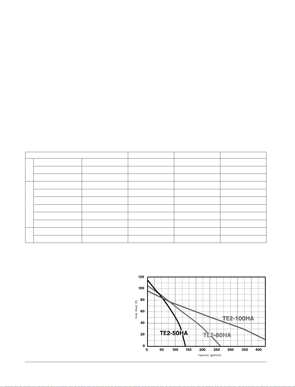
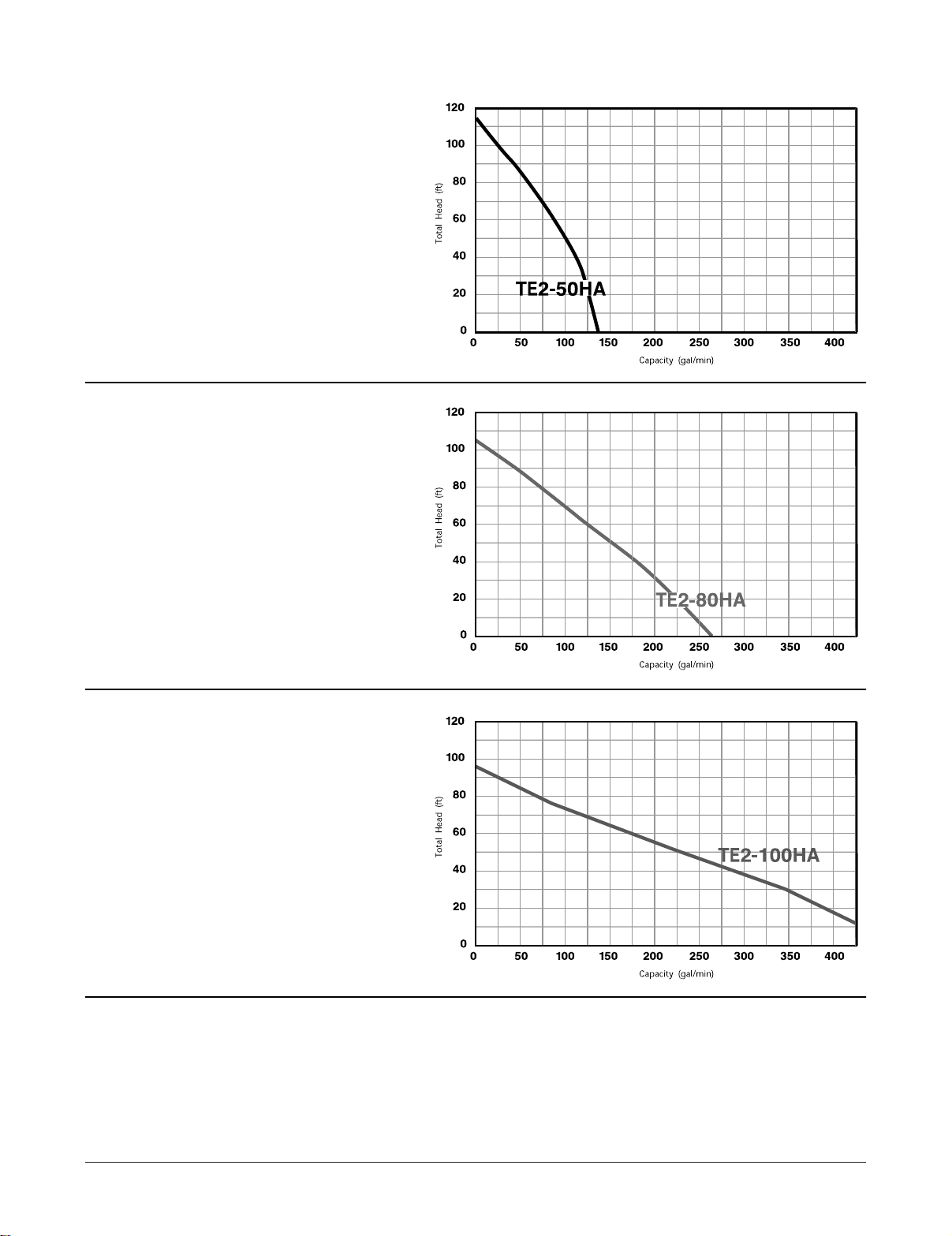
1-5 Performance Curves
Refer to the performance curves for the pumping capacity of TE3 series centrifugal pumps.
GROUP
PERFORMANCE
Introduction Page 3
MODELS
TE3-50HA
TE3-80HA
TE3-100HA
INDIVIDUAL
PERFORMANCE
MODEL
TE2-50HA
INDIVIDUAL
PERFORMANCE
MODEL
INDIVIDUAL
PERFORMANCE
Page 4 Introduction
Tsurumi’s Operation, Service, and Repair Manual
TE3-80HA
MODEL
TE3-100HA
Introduction Page 5
Tsurumi’s Operation, Service, and Repair Manual
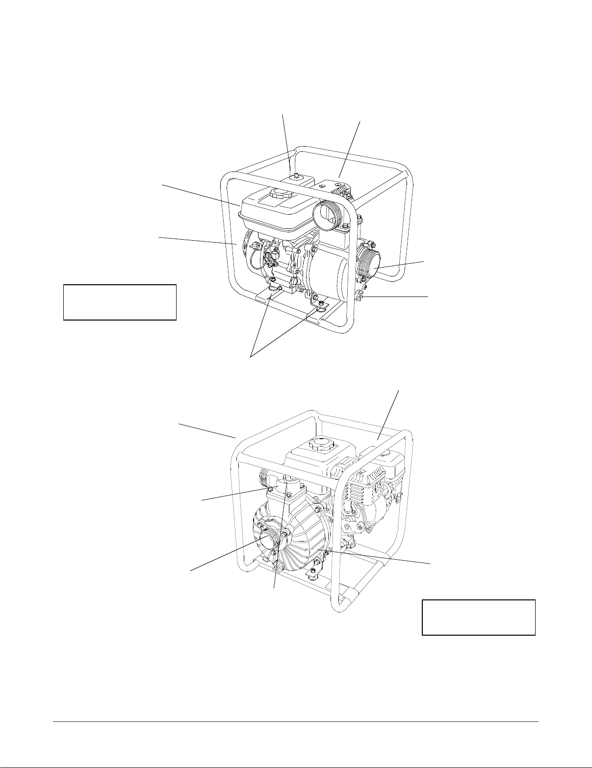
Vibration
Isolation Mounts
Suction
Fitting
Pump
Casing
Tubular
Frame
Engine Controls
(Next to Air Cleaner)
Honda
Engine
Fuel
Tank
Priming
Plug
Check Valve
(Under Suction Fitting)
Discharge
Fitting
Engine
Muffler
A
ir
Cleaner
Drain Plug
MODEL TE3-80HA
SHOWN
MODEL TE3-50HA
SHOWN
OPERATING INSTRUCTIONS
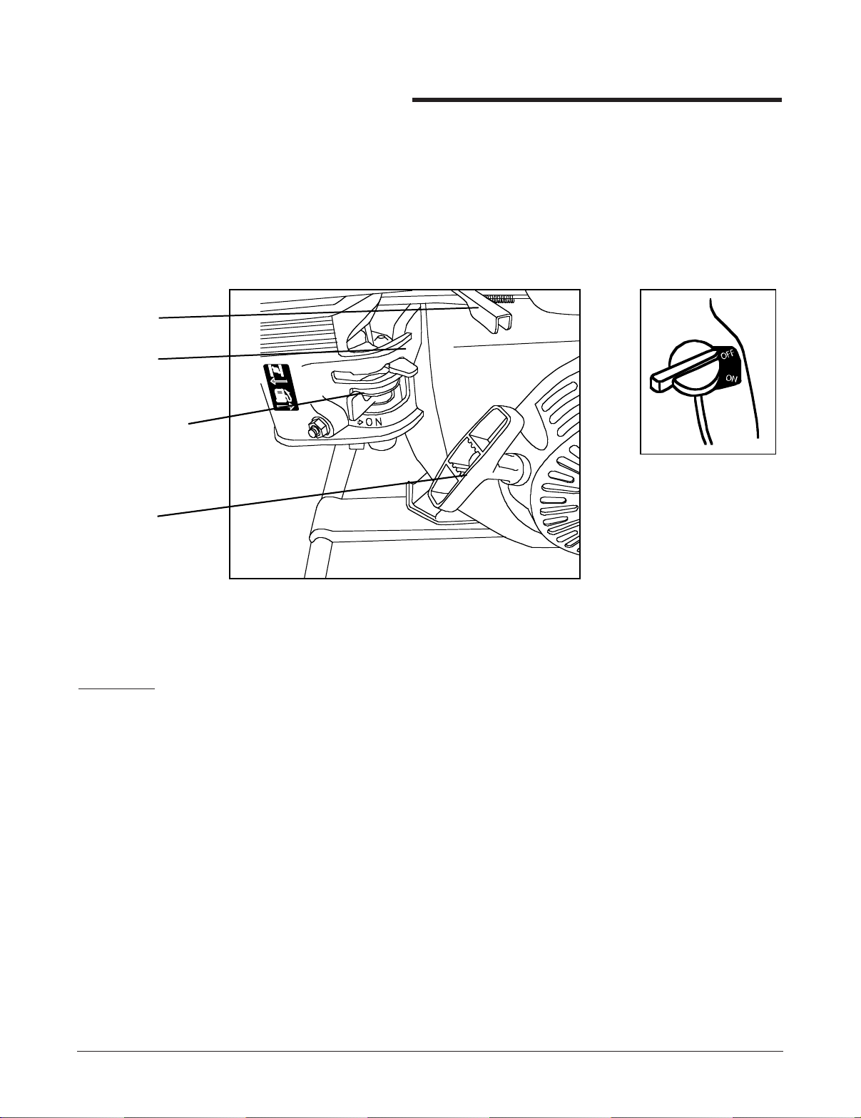
2-1 Operating Controls
A. The centrifugal pump is operated using the engine operating controls. The engine controls
are located at the engine end of the pump frame.
B. The controls consist of a throttle lever (for speed control), choke lever (for cold weather
starting), fuel shutoff lever (to prevent fuel spills), and a recoil starter (to turnover engine
by hand). (Refer to Figure 2-1.)
2-2. Check the Engine Oil Level
CAUTION:
• ENGINE OIL IS A MAJOR FACTOR AFFECTING PERFORMANCE AND SERVICE LIFE.
NON-DETERGENT OILS AND 2-STROKE OILS ARE NOT RECOMMENDED BECAUSE
THEY HAVE INADEQUATE LUBRICATING CHARACTERISTICS
• CHECK THE OIL LEVEL WITH THE ENGINE ON A LEVEL SURFACE AND THE ENGINE
STOPPED.
A. Use Honda 4-stroke oil, or use an equivalent high detergent, premium quality motor oil cer-
tified to meet or exceed U.S. automobile manufacturer’s requirements for Service
Classification SG, SF. Motor oils classified SG, SF will show this designation on the container. SAE 10W/30 is recommended for general, all-temperature use.
B. Other viscosity grades (see Figure 2-2) may be used when the average temperature in your
area is within the indicated range.
Page 6 Operating Instructions
Tsurumi’s Operation, Service, and Repair Manual
Throttle
Lever
Choke
Lever
Recoil
Starter
Hand Grip
ON/OFF Switch
(Located on Recoil
Starter Shroud)
Figure 2-1: Operating Controls
Fuel Shutoff
Valve
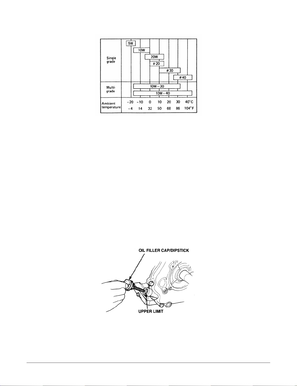
C. When checking oil, observe the following (refer to Figure 2-3):
(1) Make sure the engine is in a level position.
(2) Remove the oil filler cap/dipstick and wipe it clean.
(3) Insert the filler cap/dipstick into the oil filler neck, but do not screw it in.
(4) Remove the filler cap/dipstick and check the oil level.
(5) If the level is low, fill to the top of the oil filler neck with the recommended oil.
(6) Reinstall the oil filler cap/dipstick.
Operating Instructions Page 7
Tsurumi’s Operation, Service, and Repair Manual
Figure 2-2: Oil Viscosity Grade-to-Temperature Recommendations
Figure 2-3: Checking Oil Level
Figure 2-2: Oil Viscosity Grade-to-Temperature Recommendations

2-3 Check Engine Fuel
WARNING
• MAKE SURE YOU REVIEW EACH WARNING IN ORDER TO PREVENT FIRE HAZARD.
• DO NOT REFILL TANK WHILE ENGINE IS RUNNING OR HOT.
• CLOSE FUEL SHUT OFF VALVE BEFORE REFUELING.
• BE CAREFUL NOT TO GET DUST, DIRT, WATER OR OTHER FOREIGN OBJECTS INTO
FUEL.
• WIPE OFF SPILLED FUEL THOROUGHLY BEFORE STARTING ENGINE.
• KEEP AWAY FROM OPEN FLAMES.
• DO NOT USE SMOKING MATERIALS WHEN FILLING THE FUEL TANK.
• DO NOT REFUEL WHILE SMOKING OR NEAR OPEN FLAME OR OTHER SUCH POTENTIAL FIRE HAZARDS. OTHERWISE FIRE ACCIDENT MAY OCCUR.
• AVOID REPEATED OR PROLONGED CONTACT WITH SKIN OR BREATHING OF VAPOR.
• KEEP OUT OF REACH OF CHILDREN.
2-4 Check Fuel Level
A. Remove cap from fuel tank. If fuel level is low, refill with unleaded automotive gasoline.
B. Fuel tank capacities are provided below:
Page 8 Operating Instructions
Tsurumi’s Operation, Service, and Repair Manual
TE3-50HA . .
TE3-80HA . .
TE3-100HA . .
. . . . . . . . . . . . . .0.95 gal.
. . . . . . . . . . . . . .1.60 gal.
. . . . . . . . . . . . .1.70 gal.
 Loading...