

Page 1

TSURUGA ELECTRIC CORPORATION
MODEL 442B
Micro P r inter
Users Manual
I-01805
Page 2

Contents
General ······················································· 1
5.3.8 BCD A-F ······································ 17
1. For Safety ················································· 2
1.1 Safety operation ···································· 2
2. Installation ················································ 3
2.1 Main body ············································ 3
2.2 Roll chart ············································· 3
2.3 Dimensions ·········································· 5
3. Description of parts ····································· 5
3.1 Front panel ··········································· 5
3.2 Rear panel ··········································· 6
4. Wiring ······················································ 7
4.1 Power supply terminals ··························· 7
4.1.1 Terminals ······································· 7
4.2 Connecter ············································ 8
5.3.9 POL logic switching ························ 18
5.3.10 Interval operation ························· 18
5.3.11 Interval time ································ 19
5.3.12 Blank line ··································· 19
5.3.13 Unit ··········································· 20
5.3.14 Message ···································· 21
5.4 Reset to factory setting ························· 22
5.5 Error message ···································· 22
5.6 LED display ········································ 22
6.Printing and function ································ 23
6.1 Interval ·············································· 23
6.2 Printing ·············································· 23
6.2.1 Printing format ······························· 23
6.2.2 Upright/Inverted printing ·················· 24
6.2.3 Test printing ·································· 25
6.2.4 Character code and unit table ··········· 25
5. Function and setting ···································11
5.1 Summary of function ·····························11
5.2 Explanation of function·························· 12
5.3 Setting ·············································· 14
5.3.1 Display ········································ 14
5.3.2 Clock ·········································· 14
5.3.3 Date ············································ 15
5.3.4 Index No., Calendar clock, Elapsed time
················································ 15
5.3.5 Printing direction ···························· 16
5.3.6 CH No. ········································ 16
5.3.7 BCD digit ····································· 17
6.3 Error ················································· 27
6.3.1 Paper end detection ······················· 27
6.3.2 Temperature error detection ············· 27
6.3.3 Synchronized signal error detection ··· 27
6.3.4 Low voltage alarm ·························· 27
7. Specification ············································ 28
7.1 Specification ······································· 28
7.2 Performance ······································· 28
7.3 General ············································· 28
7.4 Printer ··············································· 29
7.5 Chart roll paper ··································· 29
7.6 Calendar clock ···································· 29
Page 3

General
Please read this manual carefully before initial operation.
Please operate this product by persons who have enough electric knowledge.
Please make sure to reach this manual to the operators of this product.
This product uses lithium batteries.
Following regulations shall be preserved when using in California state, USA.
◆Regulations for perchlorate in used batteries◆
About California DTSC's perchlorate best management practices.
Perchlorate Material – special handling may apply,See
http://www.dtsc.ca.gov/hazardouswaste/perchlorate.
Please confirm each product incorporates the following accessories.
(1) 442B Main body (2) Connector with 2m flat cable/without no connector on top
(3) Chart paper (one roll) (4) Users manual
MODEL 442B
TSURUGA ELECTRIC CORPORATION
1
Page 4
MODEL 442B
1. For Safety
1.1 Safety operation
For safety operation, please follow the instruction herein under. There are two symbols
marks for safety in this manual.
WARNING
Operation error might be caused of human death or serious wound.
CAUTION
Operation error might be caused of slight wound to operators or damage to other instruments
related to this product.
WARNING
Since this product do not have power switch, this product works
immediately after connecting power line.
Do not touch the power supply terminals while powered, otherwise
it might be caused of electric shock.
CAUTION
Described specification in this manual is the one 15 min. or longer
passed after power supply.
In case of installing this product to cabinet housing, make sure to
exchange air inside to keep inside temperature under 50℃
Keep space when installing more than 2 products. No space
installation between products might shorten products lifetime by
their self-heating.
Do not install this product in the following environment where;
Exposed to rain, water drops or directs sunlight.
High temperature or humidity, much dust or corrosive gas.
Affected by external noise, ra dio waves or sta t ic electricity.
Affected by vibration, shock.
Store this product at –20 to 60 ℃.
Wipe off front panel and housing with dry soft cloth. If necessary,
use close with small amount of synthetic detergent for cleaning.
Do not use an organic solvent such as thinner, benzine for front
panel or housing cleaning, which might damage shape and color
of front panel and housing.
2
TSURUGA ELECTRIC CORPORATION
Page 5
2. Installation
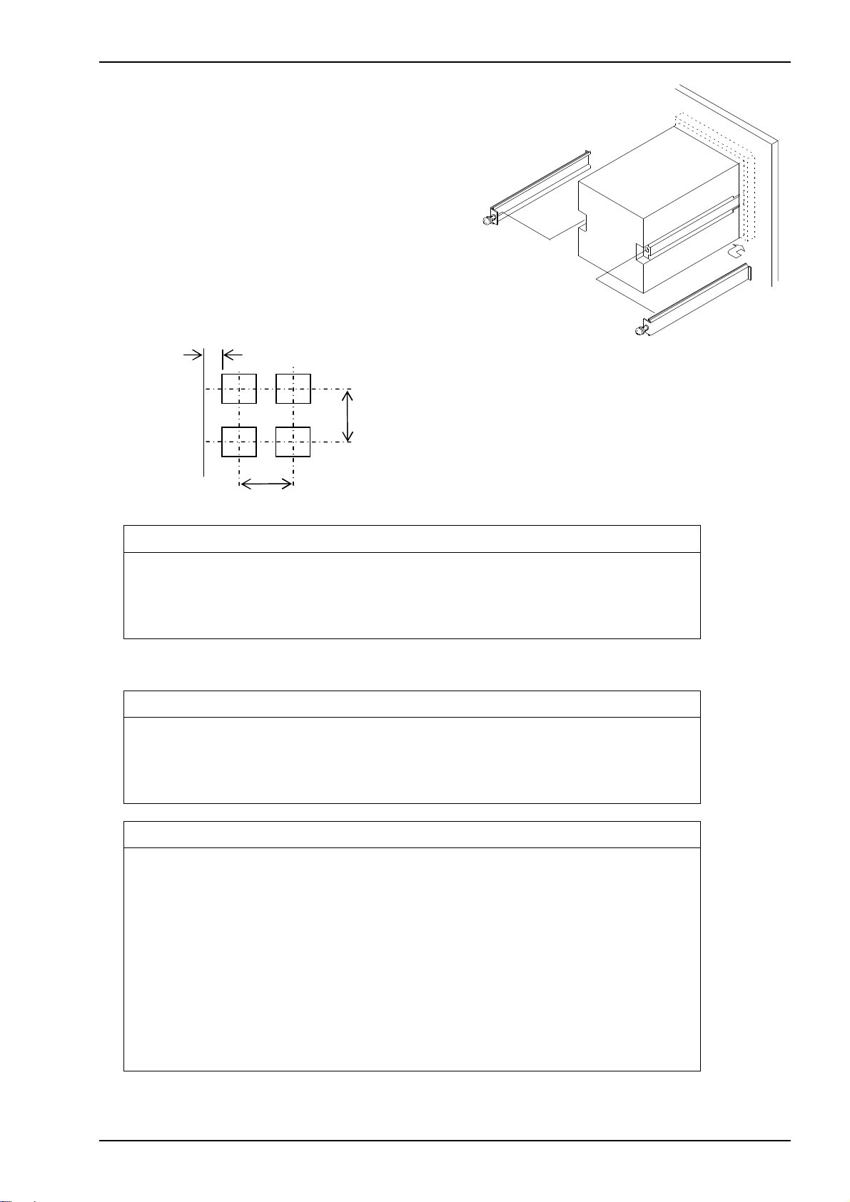
2.1 Main body
Insert a main body to front side of panel, and fix
it with screws at both sides from back.
Panel cutout : 92
+0.8
0
× 92
+0.8
0
mm
Panel thickness: 1 to 6 mm
Note) 1.5mm or more thickness is
recommended in case of aluminum
panel.
Tightening torque: 0.2 to 0.3N・m
15mm
Installation pitch between two products.
min120
min120
CAUTION
Do not tight too much a screw that might damage housing.
Use fan, etc, for forced draft in case of installing more than 2
products.
2.2 Roll chart
WARNNING
Do not touch thermal head and it’s around after printing, where
high temperature is supposed.
Replace roll chart or clean head after the temperature of head falls.
CAUTION
Do not insert fingers or alien substances into printer. Printer
cutter might injure fingers etc.
Do not open a roll chart cover by pressing Open/Close button
while printing.
Do not press Open/Close button while holding a roll chart cover
down.
Do not pull up roll paper while closing a roll chart cover.
Give full attention not to insert fingers when closing a roll chart
cover.
Do not insert alien substanc es to driving gear when closing a roll
chart cov er.
MODEL 442B
REAR
TSURUGA ELECTRIC CORPORATION
3
Page 6
MODEL 442B
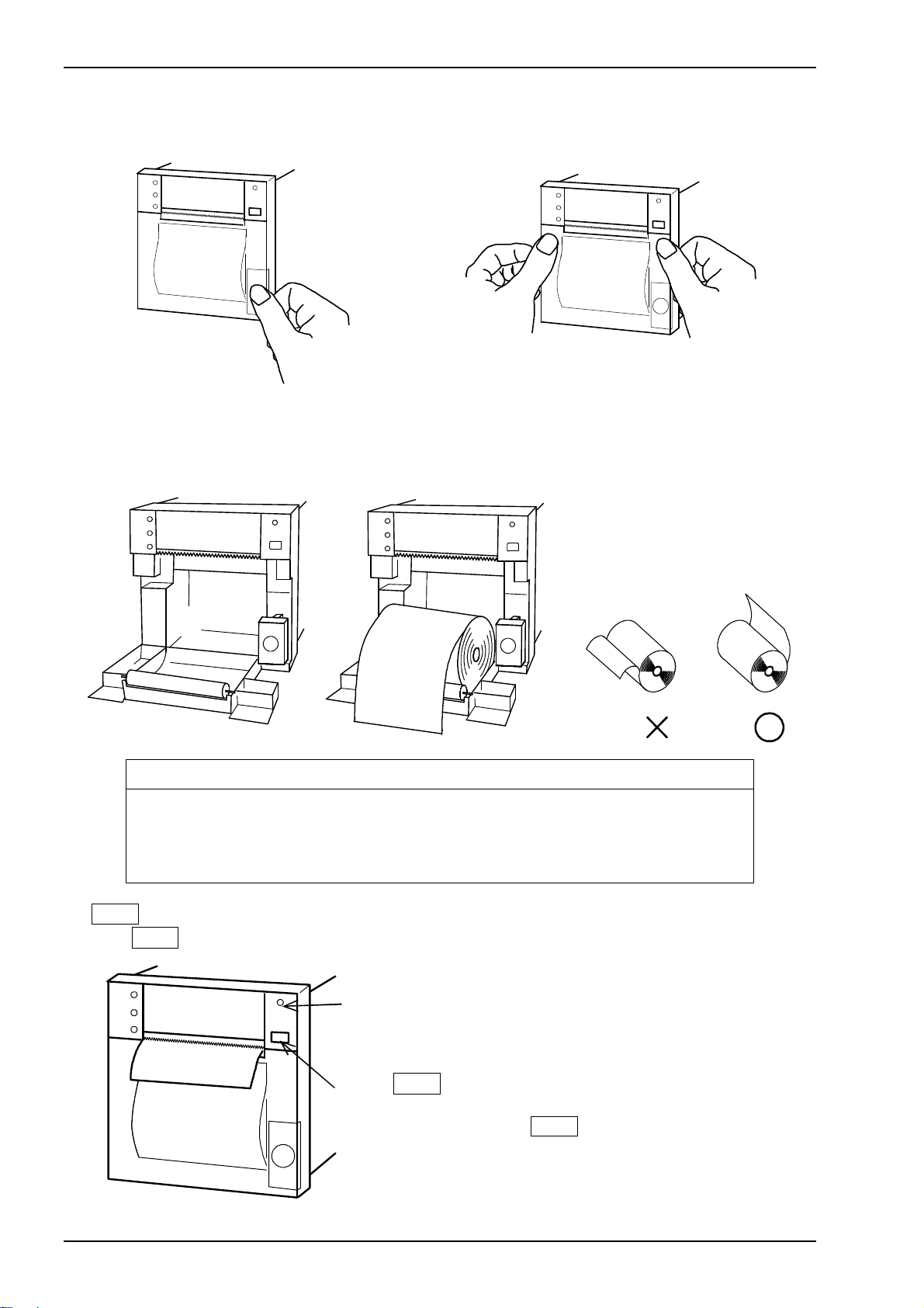
(1) Method of opening and shutting roll paper cover
●How to open a roll chart cover
Press Open/Close button for a roll chart cover.
(2) Roll chart setup
Setup a roll chart in appropriate direction shown in the drawing below.
Draw a tip of chart paper outward, and close a roll chart cover.
●How to close a roll chart cover
Press both side of a roll chart cover.
Method of installing roll chart.
CAUTION
Do not bend roll chart inside. Paper might be jammed.
Do not use first turn of a roll chart where is pasting part. No print
is available in this part.
(3) FEED Key
Press FEED key, and confirm POWER LED turns ON.
POWER LED
Confirm LED turns ON
Press FEED key
Note) Press FEED key, and confirm paper feed.
In case a roll chart cover is not closed
completely, paper feed might not be done,
and be caused of printing error.
4
TSURUGA ELECTRIC CORPORATION
Page 7
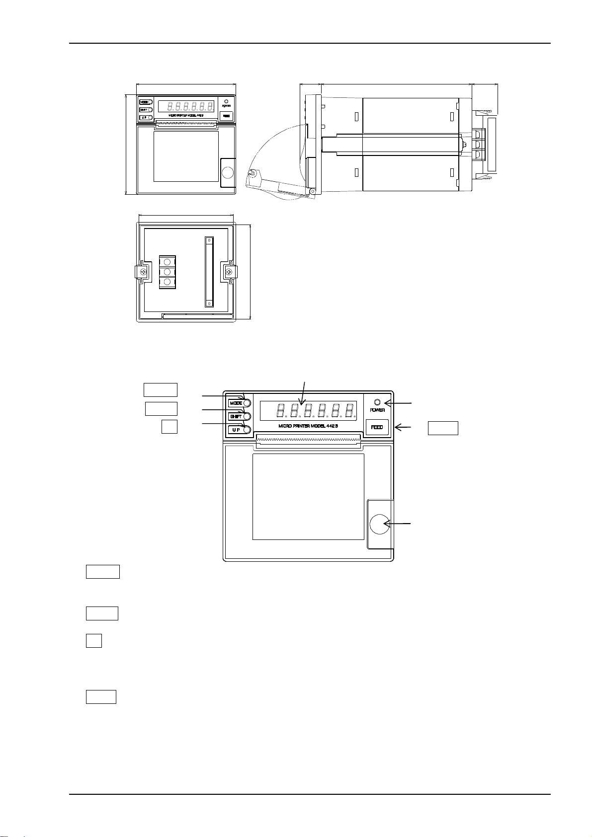
2.3 Dimensions
96
96 20.5
91
91
unit: mm
3. Description of parts
3.1 Front panel
① MODE Key
Switching Setting Mode during operation.
Switching each mode at Setting Mode.
② SHIFT Key
Digit selection for Set Value at Setting Mode.
③ UP Key
Set Value change at Setting Mode.
④ POWER LED
LED ON at powered. LED blinking at paper end and temperature error.
⑤ FEED Key
One line feeding per one press. Continuous feeding by continuous pressing.
This Key is to setup a chart roll, as well.
⑥ Open/Close button for chart roll cover
Press this button to replace a chart roll.
①MODE Key
②SHIFT Key
③UP Key
Display
④POWER LED
⑤FEED Key
⑥Open/Close button
MODEL 442B
MAX25145
for chart roll cover.
TSURUGA ELECTRIC CORPORATION
5
Page 8
MODEL 442B
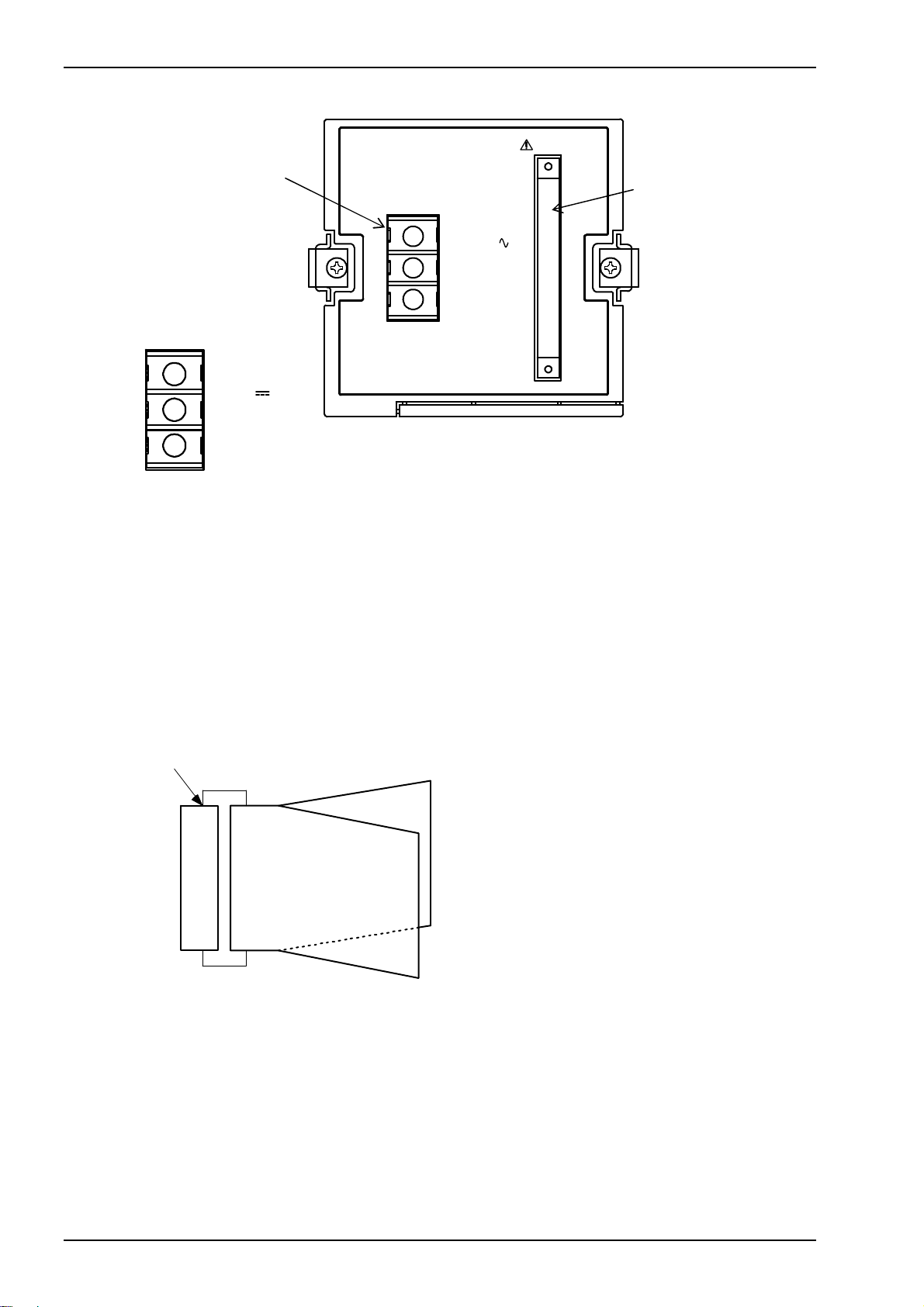
3.2 Rear panel
⑦Power terminal
100V-240V
50/60Hz 17VA
At 24V DC power
G
+
-
NC
24V
0.7A
⑦ Power terminal
For power supply
⑧ BCD connector
40 pins connector each for A and B line.
Input is TTL level, and output Transistor.
2 x flat cables (2m, 40 cores) are connected to the connector.
Each is connected to A or B line cable.
Polarity mark:△
Blineside1stcable
(bottom side)
A line side 1st cable
(upper side)
B line side 40th cable
(bottom side)
Top view
Alineside40thcable
(upper side)
DATA
⑧ BCD connector
6
TSURUGA ELECTRIC CORPORATION
Page 9
MODEL 442B
4. Wiring
WARNNING
After turn Power Off, do wiring works. Otherwise, electric shock
might be assumed.
Don’t do wiring works with wet hands or under high humid
environment. Otherwise, electric shock might be assumed.
Do not touch power terminals while powered. Otherwise, electric
shock might be assumed.
CAUTION
Do correct wiring. Wrong wiring might be caused of product
damages.
Use specified power and load in specification. Wrong power and
load might be caused of product damage.
4.1 Power supply terminals
4.1.1 Ter m in als
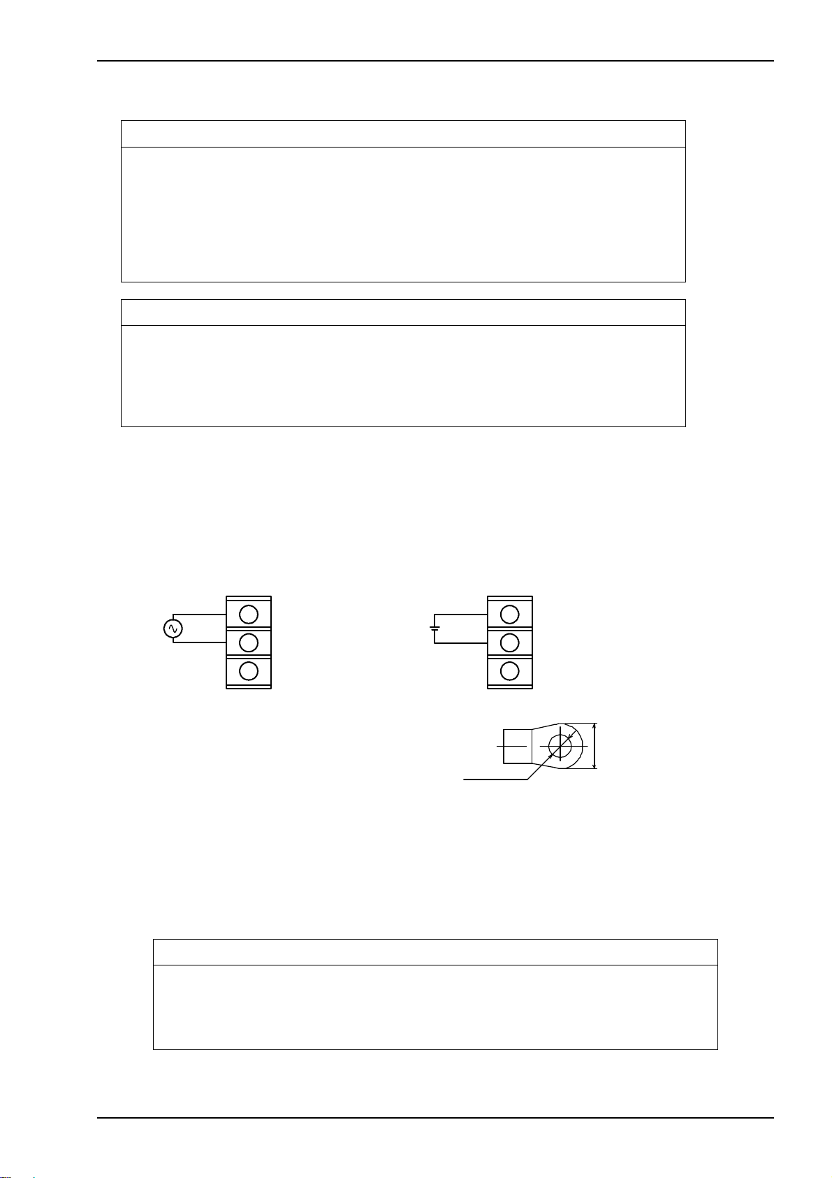
Remove a terminal cover of power supply on the rear side of the product, and
do wiring. After wiring is completed, sure to reinstall the cover.
● Power terminal arrangement
A.C. power D.C. power
100V-240V AC
50/60Hz
G
+
24V
-
Terminal screws : M3
Tightening Torque : 0.46 to 0.62N・m
Crimping terminal : see drawing (right)
φ3.2min.
● Power supply
Power supply specification is described on nameplate of the product.
○ AC power… allowable range 90 to 250V AC. (-A: 100V/200V AC rated)
○ DC power… allowable range 21.6 to 26.4V DC. (-9: 24V DC rated)
Connect + side of DC power to + terminal, and –side to – terminal.
G, NC has no function.
+
-
NC
24V DC
8max.
CAUTION
Supply power specified. Wrong power might damage the product.
Get rated power within 1 sec. after supply power.
Wait 10 sec . or more before re supply power.
TSURUGA ELECTRIC CORPORATION
7
Page 10
MODEL 442B
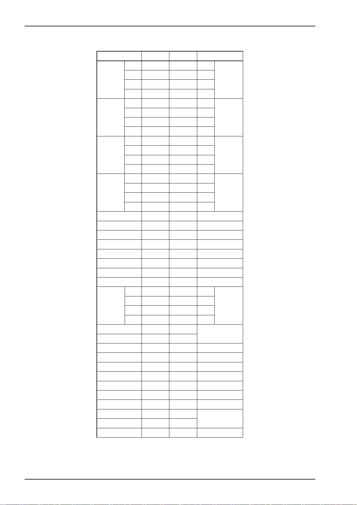
4.2 Connecter
●Pin arrangement
Function A line B line Function
1 1 1 1
DATA
0
10
2 2 2 2
4 3 3 4
DATA
10
1
8 4 4 8
1 5 5 1
DATA
2
10
2 6 6 2
4 7 7 4
DATA
10
3
8 8 8 8
1 9 9 1
DATA
4
10
2 10 10 2
4 11 11 4
DATA
10
5
8 12 12 8
1 13 13 1
DATA
6
10
2 14 14 2
4 15 15 4
DATA
107
8 16 16 8
UNIT 0 17 17
UNIT 1 18 18
UNIT 2 19 19
UNIT 3 20 20
UNIT 4 21 21
UNIT 5 22 22
UNIT 6 23 23
UNIT 7 24 24
POL
―――――
DP1
―――――
DP2
―――――
DP3
―――――
DP4
―――――
DP5
―――――
DP6
―――――
DP7
1 25 25 1
CH
№10
0
2 26 26 2
4 27 27 4
CH
№10
8 28 28 8
MSG 1 29 29
MSG 2 30 30
MSG 4 31 31
MSG 8 32 32
-
――
P/N
―――――――
SYNC
COM 33 33 COM
- 34 34 -
――――――――
PRINT
―――――――
FEED
35 35
36 36
――――――
TIME
―――――――――
RESET
COM 37 37 COM
BUSY 38 38
PE 39 39
-
COM 40 40 COM
Note) Do not connect to N/C pins.
The upper bar means negative logic.
1
8
TSURUGA ELECTRIC CORPORATION
Page 11
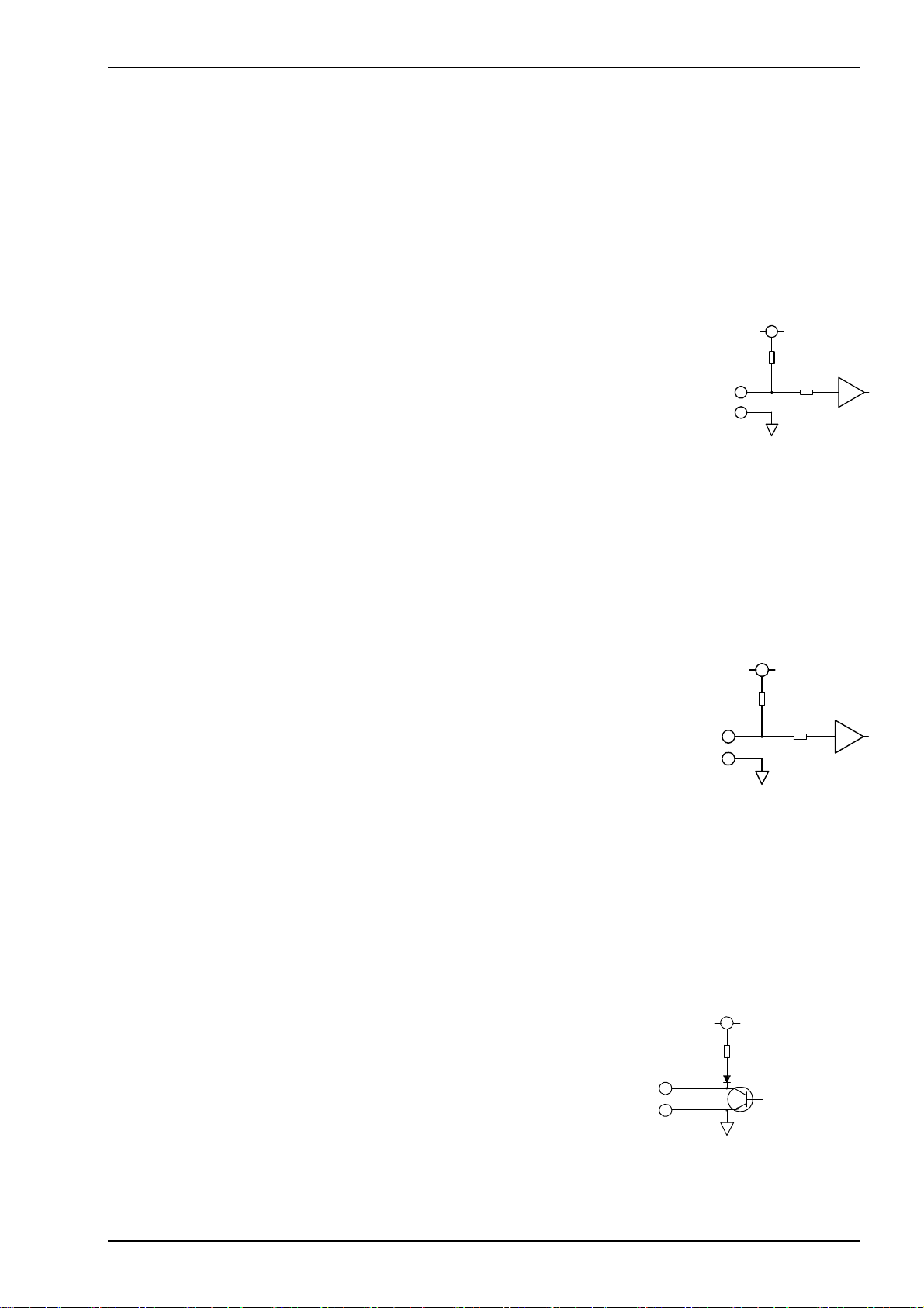
●Input/Output signal
Data input: DATA, UNIT, POL, DP
I
IL ≦ -1mA, “L”= 0 to 1.5V, “H”=3.5 to 5V
―――
, CH No., and MSG
DATA: 8 digits BCD input
At positive logic input: L level = “0”, H level = “1”
At negative logic input: L level = “1”, H level = “0”
POL: BCD data polarity input
At positive logic input: L level = “-”, H level = “+”
At negative logic input: L level = “+”, H level = “-“
Unit: Unit code input
At positive input: L level = “0”, H level = “1”
At negative input: L level = “1”, H level = “0”
MSG: Message input
At positive input: L level = “0”, H level = “1”
At negative input: L level = “1”, H level = “0”
CH No.: CH No. input
At positive input: L level = “0”, H level = “1”
At negative input: L level = “1”, H level = “0”
―――
: Decimal input
DP
Connect COM terminal for setting.
Printing an upper digit decimal only when multiple setting.
Control input: P/N
I
――
―――――――
, SYNC
IL≦ -1mA, “L”= 0 to 1.5V, “H”=3.5 to 5V Active “L”
――
P/N
――――――――
, PRINT
―――――――
, FEED
: Logic switching input
Logic setting for DATA, UNIT, POL, CH, MSG.
Positive logic input at H level.
Negative logic input at L level.
―――――――
SYNC
: Synchronized signal input
Acquire data at rising of SYNC signal.
No acquirement of data at L level.
Minimum pulse width 2 msec.
――――――――
RESET
: Reset signal input (L level detection)
Release Interval operation, Index No..
Return Synchronized signal error. Minimum pulse width 2 ms.
―――――――
: Paper feed signal (L level detection)
FEED
Minimum pulse width 2ms
――――――――
PRINT
――――――
TIME
: Data print command (L edge detection)
Minimum pulse width 10ms
: Index No., Calendar clock, Elapsed time command (L edge detection)
Accept at Interval operation OFF.
Minimum pulse width 10ms.
Control output: BUSY, PE
TTL level, Fo=1
Transistor output
Rated output: 30V DC, 30mA Max.
PE: Paper end output
OFF at paper end (H level)
BUSY: Signal output at printing
OFF at printing, paper end, synchronized signal error, roll chart
cover opened (H level)
――――――
, TIME
, and RESET
――――――――
BUSY,PE
COM
15kΩ
5V
MODEL 442B
5V
15kΩ
100kΩ
5V
100kΩ
IC
IC
TSURUGA ELECTRIC CORPORATION
9
Page 12
MODEL 442B
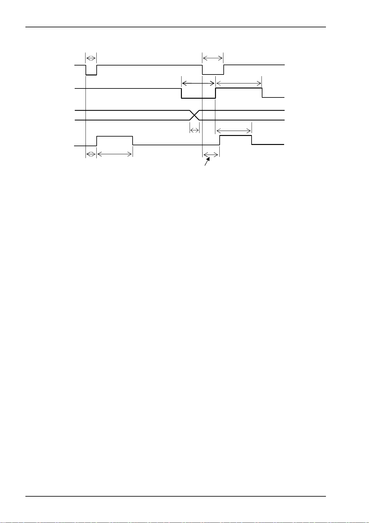
● Timing chart
――――――――
PRINT
or Time-Up
―――――――
SYNC
BCD data
BUSY
A: Min. 10ms
B: Max. 5ms Input time of data.
C: Max. 200ms
Note) In the case of blank line setting, approx.150ms blank line is added.
The time is changed up to printing rate.
T1: 2ms to 1 sec. Note) Synchronized signal error at t < T1 and 1 sec. or longer.
T2: Min. 5ms (SYNC
A
B
C
―――――――
H level holding time)
A
T2 T1
t
Printing after rising L of SYNC.
C
10
TSURUGA ELECTRIC CORPORATION
Page 13
5. Function and setting
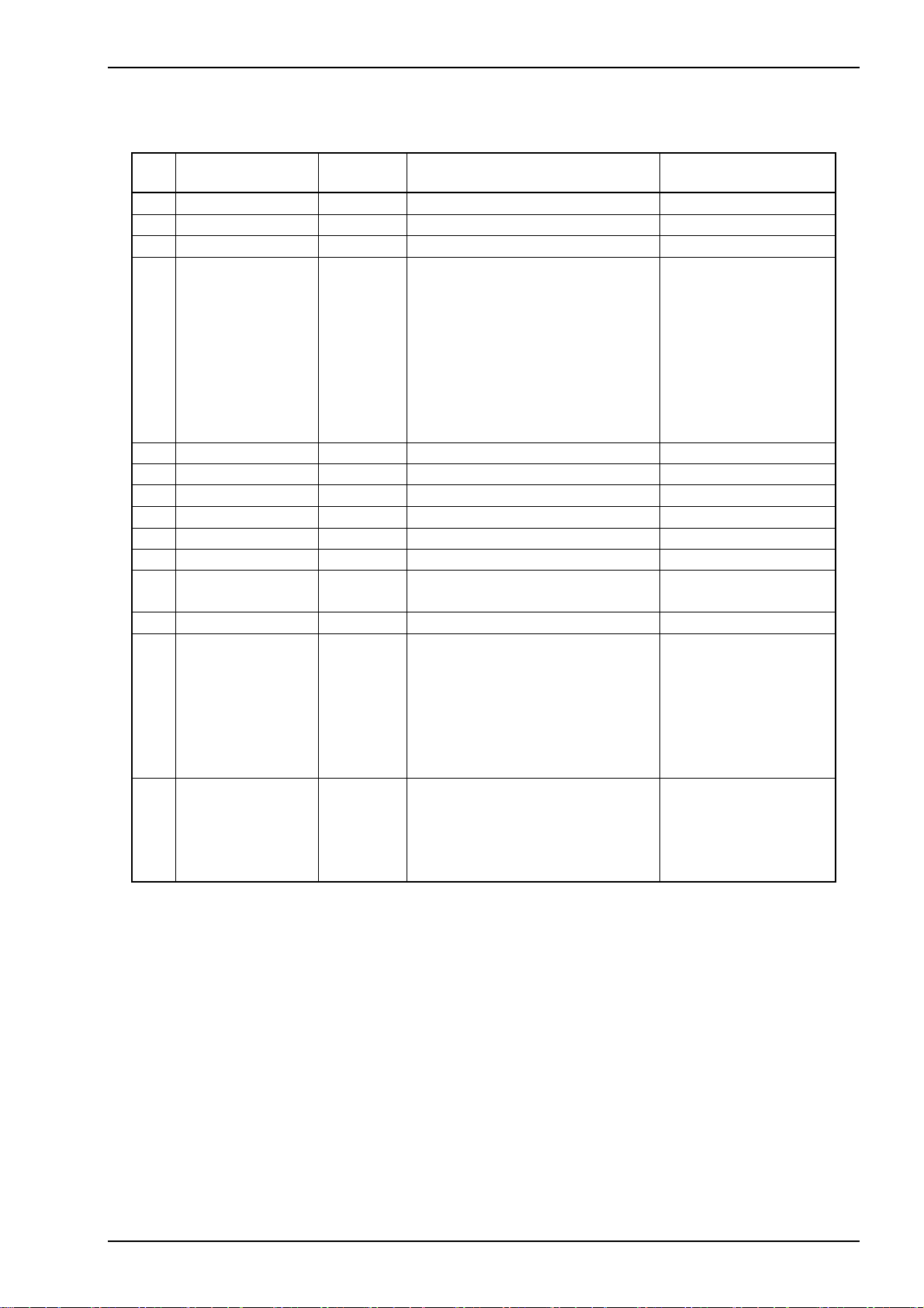
5.1 Summary of function
Code
№
01 Display setting
02 Clock setting
03 Date setting
04 Index No.,
Calendar clock, 1: Index No.
Elapsed time 2: Hours/Minutes/Second
printing 3: Year/Month/Date
4: Year/Month/Date,
Hours/Minute/Second
5: Elapsed time Note2)
6: Index No., Hours/Minute/Second
7: No printing
05 Printing direction
06 CH No. printing
07 BCD digit setting
08 BCD A to F setting
09 POL logic switching
10 Interval operation
11 Interval time
99 hr. 59 min. 59 sec.
12 Blank line printing
13 Unit setting
0.20 to FD 0.20
1.20 to FD 1.20
2.20 to FD 2.20
3.20 to FD 3.20
4.20 to FD 4.20
5.20 to FD 5.20
14 Message setting
0.20 to FD 0.20
1.20 to FD 1.20
2.20 to FD 2.20
3.20 to FD 3.20
Note1) Calendar clock is set at delivery.
Note2) Valid at Interval operation ON.
Note3) See 6.2.4 character code.
Function Display Description Factory set
0: Hours/Minutes/Second, 1: OFF 0
Hours/Minutes Note 1)
Tear/Month/Date Note 1)
0: No printing
0: Upright, 1: Inverted 0
0: No printing, 1: Printing 0
1 to 8 8
0: ASCII code, 1: Space 0
0: Positive, 1: Negative 0
0: OFF, 1: ON 0
00 hr. 00 min. 01 sec. to 00 hr. 00 min. 01 sec.
0 to 9 0
No. Character code Note3) No. Character code
No. Character code Note3) No. Character code
MODEL 442B
0
TSURUGA ELECTRIC CORPORATION
11
Page 14

MODEL 442B
5.2 Explanation of function
Code No.01: Display setting
Switching Hour/Minute/Second display and OFF display.
Code No.02: Time setting
Adjusting Hour of calendar clock.
24 hour (0 to 23) adjustable.
Second unit setting is unavailable. (00 sec. only)
Code No.03: Date setting
Adjusting Year/Month/Date of calendar clock.
Setting the last two digits of AD (00 to 99)
Code No.04: Index No., Calendar clock, Elapsed time printing
Setting Index No., Calendar clock, Elapsed time printing.
Index No., Elapsed time memorized even if changing code No.10:
With/Without Interval operation.
Index No. : Count 0001 to 9999
After 9999, start counting from 0001.
Back to 0001 after supplying power or RESET
Count-up
When the interval action is enabling (ON), count-up will be done at
each interval time.
When it is disabling (OFF), count-up will be done by inputting the
PRINT signal.
To print, input the TIME signal.
Counter-up dose not work at paper end.
Elapsed time: 00 hour 00 minute 00 second to 99 hour 59 minute 59 second
After 99 hour 59 minute 59 second, back to 00 hour 00 minute 00
second.
Back to 00 hour 00 minute 00 second after supplying power or
――――――――
RESET
signal.
Elapsed time works even if paper end.
Valid at Interval operation ON.
Code No.05: Printing direction
Setting Upright or Inverted printing.
Code No.06: CH No. printing
Setting With/Without CH No. printing.
Code No.07: BCD digit setting
Setting BCD digits (1 to 8).
Digit not to be set prints SP (space) regardless of DATA input, DP input.
――――――――
signal.
12
TSURUGA ELECTRIC CORPORATION
Page 15
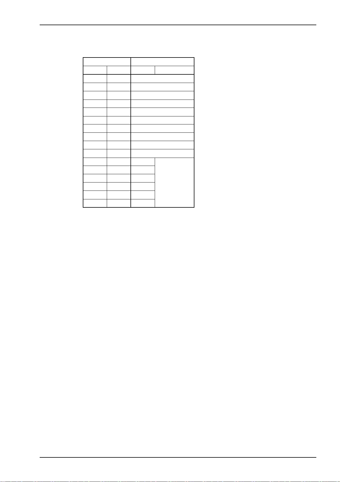
Code No.08: BCD A-F setting
Switching to SP (space) printing at BCD data input A to F code.
◆BCD data and printing
BCD BCD number setting
8421 HEX 0 1
0000 0 0
Printing example at positive logic of BCD data.
0001 1 1
0010 2 2
0011 3 3
0100 4 4
0101 5 5
0110 6 6
0111 7 7
1000 8 8
1001 9 9
1010 A :
1011 B ;
1100 C <
1101 D =
SP
1110 E >
1111 F ?
Code No.09: POL logic switching
Switching POL logic.
Code No.10: Interval operation
Setting ON/OFF for Interval operation.
Code No.11: Interval time
Setting interval time.
Code No.12: Blank line printing
Setting Blank line (0 to 9)
No blank line is inserted at 0.
4 blank lines are fixed at the following condition.
At Interval time operation ON, Interval time 00:00:01, 4 or more blank lines
At Interval time operation ON, use PRINT
―――――――
signal input.
Code No.13: Unit setting
Register free Unit characters. (6 characters) (See 6.2.4 character code)
Reg i ste red U n it, when UNIT 0 to 7 sig nal i s bei ng 11111111, is pr inted.
Code No.14: Message setting
Register free Message characters. (4 characters) (See 6.2.4 character code)
Registered Message, when MSG1,2,4,8 signal is being 1111, is printed.
MODEL 442B
TSURUGA ELECTRIC CORPORATION
13
Page 16
MODEL 442B
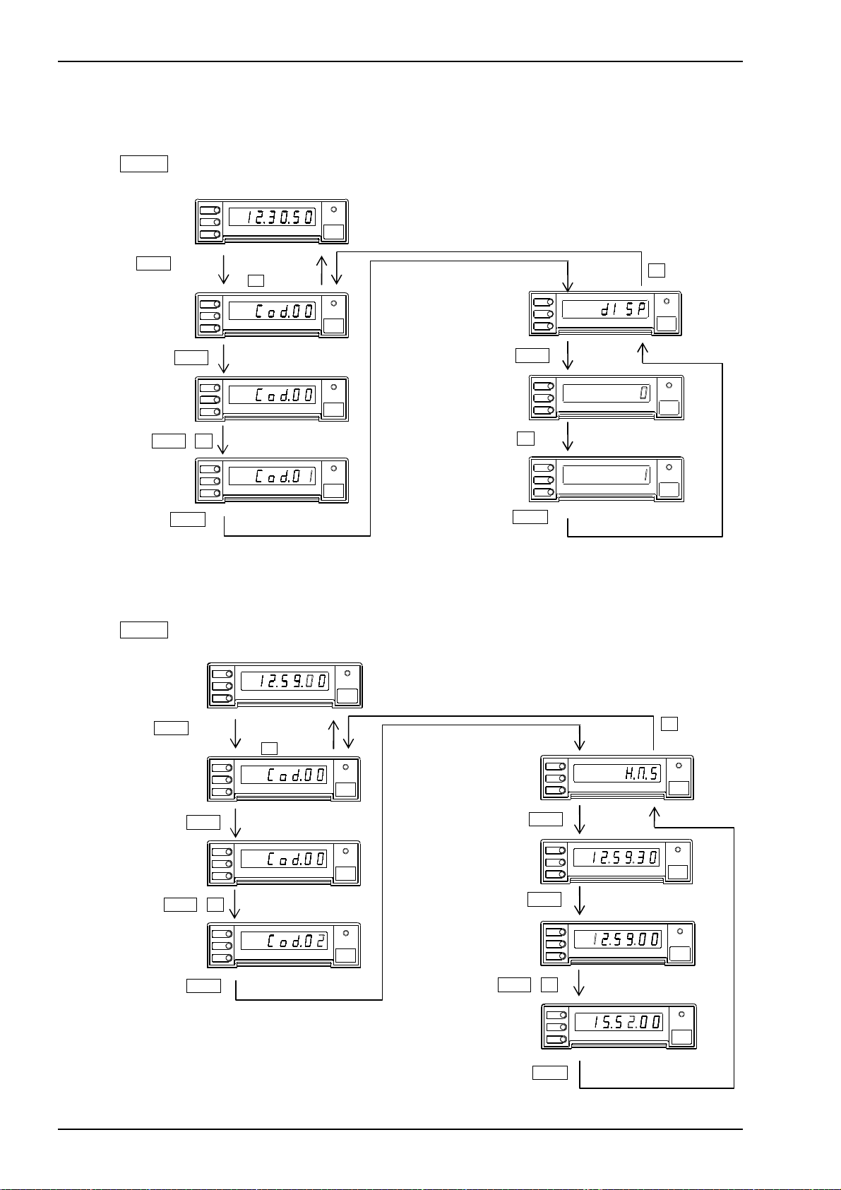
5.3 Setting
5.3.1 Display
Example) Set Hour/Minute/Second display to OFF.
Press MODE key for 1 sec. or more during operation to get setting mode (Display:
Setting code No.01
to change
In operation
MODE 1 sec
SHIFT
SHIFT , UP
MODE
SHIFT
MICRO PRINTER MOD EL 442B
UP
Memorized by
UP Key
MODE
SHIFT
MICRO PRINTER MOD EL 442B
UP
POWER
FEED
POWER
FEED
Back to Cod.00 by code No. to be set.
Code 01
Display s etting
MODE
SHIFT
MICRO PRINTER MOD EL 442B
UP
SHIFT
MODE
SHIFT
MICRO PRINTER MOD EL 442B
UP
POWER
FEED
MODE
SHIFT
UP
MICROPRINTER MODEL 442B
UP
MODE
SHIFT
MICRO PRINTER MOD EL 442B
UP
POWER
FEED
MODE
SHIFT
UP
MICRO PRINTE R MODEL 442B
MODE
MODE
5.3.2 Clock
Example) Adjusting clock 12. 59. 30 to 15. 52. 00.
Press MODE key for 1 sec. or more during operation to get setting mode (Display:
Setting code No.02
to change
In operation
MODE 1 sec
SHIFT
SHIFT , UP
MODE
MODE
SHIFT
MICRO PRINTE R MODEL 442B
UP
Completed by
UP Key
MODE
SHIFT
MICRO PRINTER MOD EL 442B
UP
POWER
FEED
Back to Cod.00 by code No. to be set.
Code 02
Clock setting
POWER
FEED
MODE
SHIFT
MICRO PRINTER M ODEL 442B
UP
SHIFT
MODE
SHIFT
MICRO PRINTER MOD EL 442B
UP
POWER
FEED
Clock display
MODE
SHIFT
MICRO PRINTER MODE L 442B
UP
SHIFT
MODE
SHIFT
MICRO PRINTER MODEL 442B
UP
POWER
FEED
MODE
SHIFT
MICRO PRINTER MODEL 442B
UP
SHIFT , UP
MODE
SHIFT
UP
MICRO PRINTE R MODEL 442B
MODE
)
UP
POWER
FEED
POWER
FEED
POWER
FEED
)
UP
POWER
FEED
POWER
FEED
POWER
FEED
POWER
FEED
14
Update Calendar clock.
TSURUGA ELECTRIC CORPORATION
Page 17
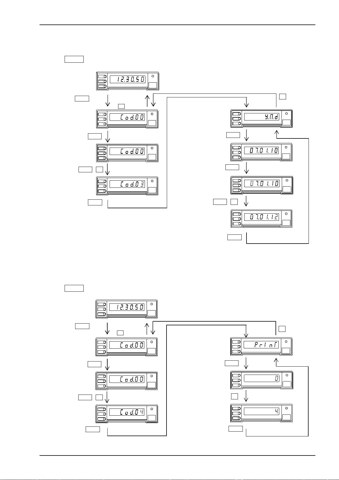
5.3.3 Date
Example) Adjusting date 07. 01. 10 to 07. 01. 12.
Press MODE key for 1 sec. or more during operation to get setting mode (Display:
In operation
MODE
SHIFT
UP
MICRO PRINTE R MODEL 442B
POWER
FEED
Back to Cod.00 by code No. to be set.
MODE 1 sec
Completed by
UP Key
MODE
SHIFT
MICRO PRINTER MOD EL 442B
UP
POWER
FEED
Code 03
Date setting
MODE
SHIFT
UP
MICRO PRINTER M ODEL 442B
)
UP
SHIFT
SHIFT
Setting code No.03
to change
MODE
SHIFT
MICRO PRINTER MOD EL 442B
UP
POWER
FEED
Date display
MODE
SHIFT
UP
MICRO PRINTER MODE L 442B
POWER
SHIFT , UP
MODE
SHIFT
POWER
MICRO PRINTER MODEL 442B
UP
FEED
SHIFT
MODE
SHIFT
UP
MICRO PRINTER MODEL 442B
MODE
SHIFT , UP
MODE
SHIFT
MICRO PRINTER MODEL 4 42B
UP
POWER
MODE
Update Calendar clock.
5.3.4 Index No., Calendar clock, Elapsed time
Example) Adjusting no print setting of “Index No., Calendar clock, Elapsed time” to
Year/Month/Date/Hours/Minute/Second.
Press MODE key for 1 sec. or more during operation to get setting mode (Display:
In operation
MODE 1 sec
MODE
SHIFT
MODE
SHIFT
MICRO PRINTER MOD EL 442B
UP
Memorized by
UP Key
MICRO PRINTER MOD EL 442B
UP
POWER
FEED
Back to Cod.00 by code No. to be set.
Code 04
Print setting
POWER
FEED
MODE
SHIFT
MICRO PRINTER M ODEL 442B
UP
Setting code No.04
to change
SHIFT
MODE
SHIFT
MICRO PRINTER MOD EL 442B
UP
POWER
FEED
SHIFT
MODE
SHIFT
UP
MICRO PRINTE R MODEL 442B
SHIFT , UP
MODE
SHIFT
POWER
MICRO PRINTER MODEL 442B
UP
FEED
UP
MODE
SHIFT
UP
MICRO PRINTER MODEL 442B
)
UP
POWER
MODEL 442B
POWER
FEED
FEED
POWER
FEED
FEED
FEED
POWER
FEED
POWER
FEED
MODE
MODE
TSURUGA ELECTRIC CORPORATION
15
Page 18
MODEL 442B
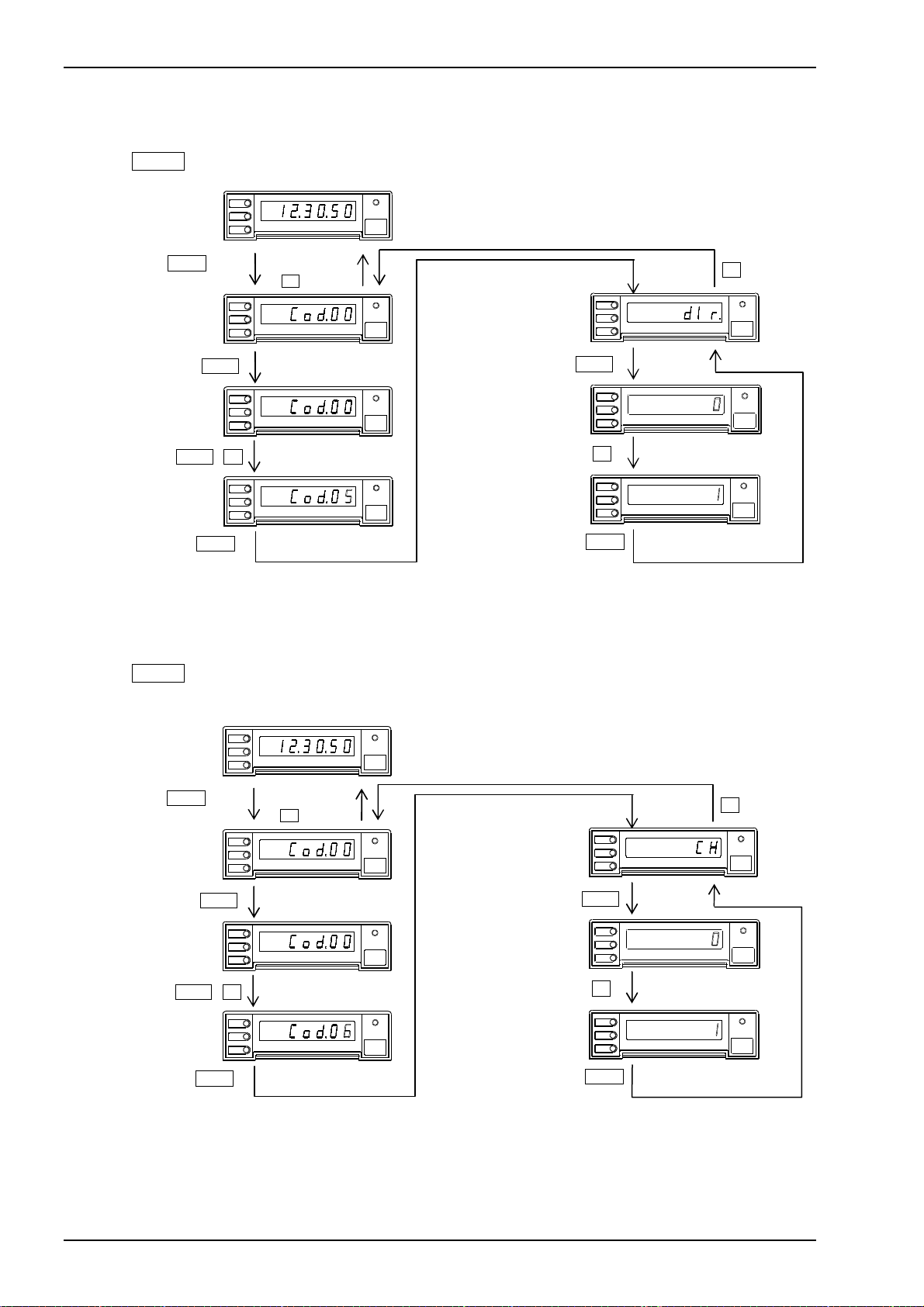
5.3.5 Printing direction
Example) Adjusting printing direction from upright to Inverted
Press MODE key for 1 sec. or more during operation to get setting mode (Display:
In operation
MODE 1 sec
MODE
SHIFT
MODE
SHIFT
MICRO PRINTER MOD EL 442B
UP
Memorized by
UP Key
MICRO PRINTER MOD EL 442B
UP
POWER
FEED
Back to Cod.00 by code No. to be set.
Code 05
Printing direction setting
POWER
FEED
MODE
SHIFT
MICRO PRINTER M ODEL 442B
UP
Setting code No.05
to change
SHIFT
MODE
SHIFT
SHIFT , UP
MODE
SHIFT
MODE
POWER
MICRO PRINTER MOD EL 442B
UP
MICRO PRINTER MODEL 442B
UP
FEED
POWER
FEED
SHIFT
MODE
SHIFT
UP
UP
MODE
SHIFT
UP
MODE
MICRO PRINTE R MODEL 442B
MICRO PRINTER MODEL 442B
5.3.6 CH No.
Example) Changing “without CH No. printing” to “with”.
Press MODE key for 1 sec. or more during operation to get setting mode (Display:
Setting code No.06
to change
In operation
MODE 1 sec
SHIFT
SHIFT , UP
MODE
MODE
SHIFT
MODE
SHIFT
MICRO PRINTER MOD EL 442B
UP
Memorized by
UP Key
MICRO PRINTER MOD EL 442B
UP
POWER
FEED
POWER
FEED
Back to Cod.00 by code No. to be set.
Code 06
CH No. print setting
MODE
SHIFT
MICRO PRINTER M ODEL 442B
UP
SHIFT
MODE
SHIFT
MICRO PRINTER MOD EL 442B
UP
POWER
FEED
MODE
SHIFT
UP
MICRO PRINTE R MODEL 442B
UP
MODE
SHIFT
MICRO PRINTER MODEL 442B
UP
POWER
FEED
MODE
SHIFT
MICRO PRINTER MODEL 442B
UP
MODE
)
UP
POWER
FEED
POWER
FEED
POWER
FEED
)
UP
POWER
FEED
POWER
FEED
POWER
FEED
16
TSURUGA ELECTRIC CORPORATION
Page 19
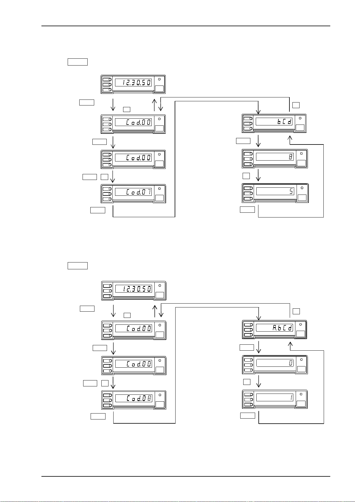
5.3.7 BCD digit
Example) Adjusting 8 digits BCD to 5 digits.
Press MODE key for 1 sec. or more during operation to get setting mode (Display:
In operation
MODE 1 sec
MODE
SHIFT
MICRO PRINTER MOD EL 442B
UP
Memorized by
UP Key
MODE
SHIFT
MICRO PRINTER MOD EL 442B
UP
POWER
FEED
Back to Cod.00 by code No. to be set.
Code 07
BCD digit setting
POWER
FEED
MODE
SHIFT
MICRO PRINTER M ODEL 442B
UP
Setting code No.07
to change
SHIFT
MODE
SHIFT
MICRO PRINTER MOD EL 442B
UP
POWER
FEED
SHIFT
MODE
SHIFT
UP
MICRO PRINT ER MODEL 442B
SHIFT , UP
MODE
SHIFT
MODE
POWER
MICRO PRINTER MODEL 442B
UP
FEED
UP
MODE
SHIFT
UP
MODE
MICRO P RINTER MODEL 4 42B
5.3.8 BCD A-F
Example) Changing character code to space at A to F code after BCD data 9.
Press MODE key for 1 sec. or more during operation to get setting mode (Display:
Setting code No.08
to change
In operation
MODE
SHIFT
MODE 1 sec
MODE
SHIFT
SHIFT
MODE
SHIFT
SHIFT , UP
MODE
SHIFT
MODE
POWER
MICRO PRINTER MOD EL 442B
UP
Memorized by
UP Key
MICRO PRINTER MOD EL 442B
UP
FEED
POWER
FEED
Back to Cod.00 by code No. to be set.
Code 08
BCD number setting
MODE
SHIFT
MICRO PRINTER M ODEL 442B
UP
SHIFT
POWER
MICRO PRINTER MOD EL 442B
UP
FEED
MODE
SHIFT
MICRO PRINTE R MODEL 442B
UP
UP
POWER
MICRO PRINTER MODEL 442B
UP
FEED
MODE
SHIFT
MICRO PRINTER MODEL 442B
UP
MODE
MODEL 442B
)
UP
POWER
FEED
POWER
FEED
POWER
FEED
)
UP
POWER
FEED
POWER
FEED
POWER
FEED
TSURUGA ELECTRIC CORPORATION
17
Page 20
MODEL 442B
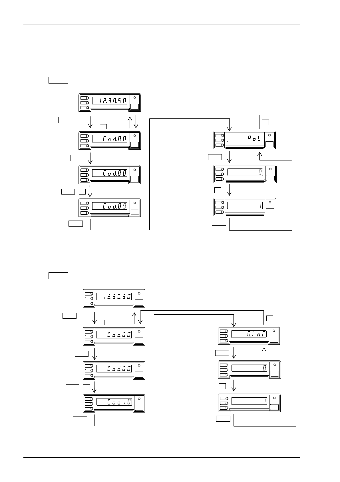
5.3.9 POL logic switching
Example) Changing logic for polarity input signal of BCD data as follows;
At positive logic input, L level = “-”, H level = “+”
↓
At positive logic input, H level = “-”, L level = “+”
Press MODE key for 1 sec. or more during operation to get setting mode (Display:
In operation
MODE 1 sec
MODE
SHIFT
MODE
SHIFT
UP
UP
MICRO PRINTER MOD EL 442B
Memorized by
UP Key
MICRO PRINTER MOD EL 442B
POWER
FEED
Back to Cod.00 by code No. to be set.
Code 09
POL logic switching
POWER
FEED
MODE
SHIFT
MICRO PRINTER M ODEL 442B
UP
SHIFT
SHIFT
Setting code No.09
to change
MODE
SHIFT
MICRO PRINTER MOD EL 442B
UP
POWER
FEED
MODE
SHIFT
UP
MICRO PRINTE R MODEL 442B
SHIFT , UP
MODE
SHIFT
MICROPRINTER MODEL 442B
UP
POWER
FEED
UP
MODE
SHIFT
UP
MICRO PRINTER MODEL 442B
MODE
MODE
5.3.10 Interval operation
Example) Changing interval operation OFF to ON
Press MODE key for 1 sec. or more during operation to get setting mode (Display:
Setting code No.10
to change
In operation
MODE 1 sec
SHIFT
SHIFT , UP
MODE
MODE
SHIFT
MICRO PRINTER MOD EL 442B
UP
Memorized by
UP Key
MODE
SHIFT
MICRO PRINTER MOD EL 442B
UP
POWER
FEED
Back to Cod.00 by code No. to be set.
Code 10
BCD interval operation setting
POWER
FEED
MODE
SHIFT
MICRO PRINTER M ODEL 442B
UP
SHIFT
MODE
SHIFT
MICRO PRINTER MOD EL 442B
UP
POWER
FEED
MODE
SHIFT
UP
MICRO PRINTE R MODEL 442B
UP
MODE
SHIFT
MICRO PRINTER MODEL 442B
UP
POWER
FEED
MODE
SHIFT
MICRO PRINTER MODEL 442B
UP
MODE
)
UP
POWER
FEED
POWER
FEED
POWER
FEED
)
UP
POWER
FEED
POWER
FEED
POWER
FEED
18
TSURUGA ELECTRIC CORPORATION
Page 21
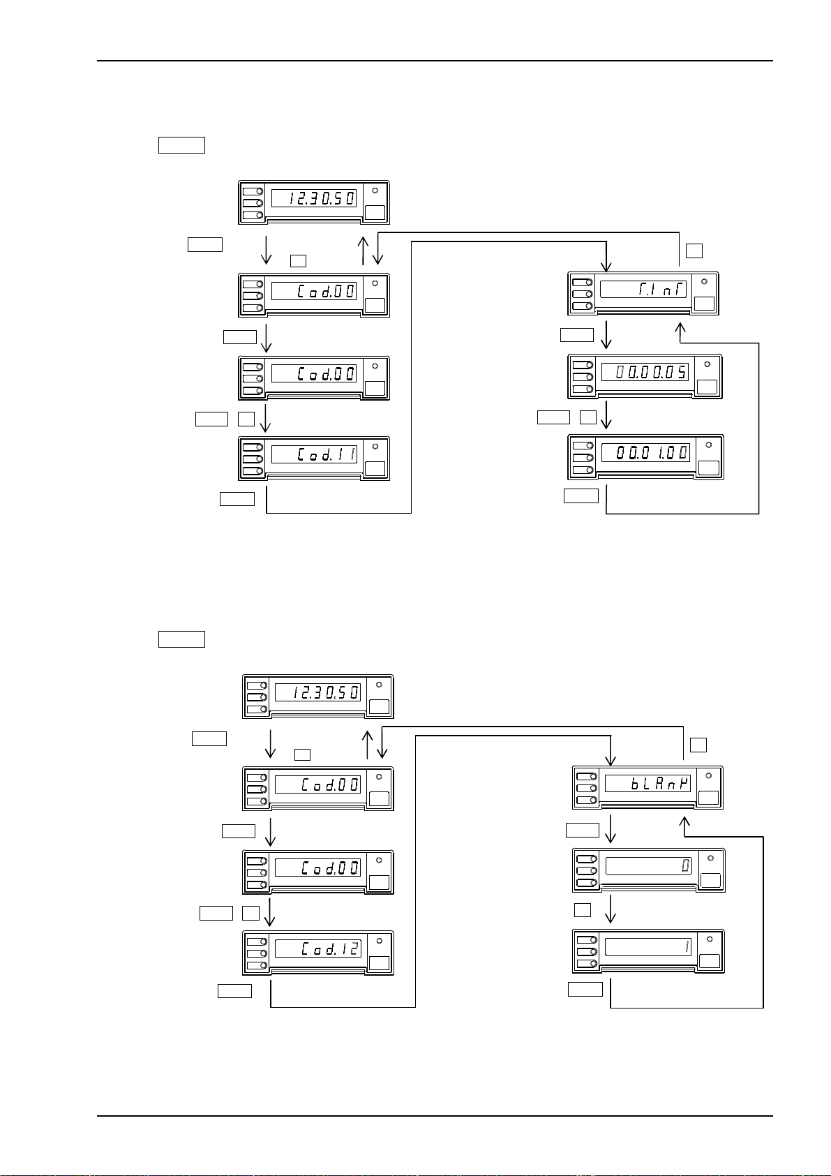
5.3.11 Interval time
Example) Adjusting interval time 5 sec. to 1 min.
Press MODE key for 1 sec. or more during operation to get setting mode (Display:
Setting code No.11
to change
In operation
MODE 1 sec
SHIFT
SHIFT , UP
MODE
SHIFT
MICRO PRINTER MOD EL 442B
UP
Memorized by
UP Key
MODE
SHIFT
MICRO PRINTER MOD EL 442B
UP
POWER
FEED
Back to Cod.00 by code No. to be set.
Code 11
Interval time setting
POWER
FEED
MODE
SHIFT
MICRO PRINTER M ODEL 442B
UP
SHIFT
MODE
SHIFT
MICRO PRINTER MOD EL 442B
UP
POWER
FEED
MODE
SHIFT
UP
MICRO PRINT ER MODEL 442B
SHIFT , UP
MODE
SHIFT
MICRO PRINTER MODEL 442B
UP
POWER
FEED
MODE
SHIFT
UP
MICRO P RINTER MODEL 4 42B
MODE
MODE
5.3.12 Blank line
Example) Adjusting “without blank line” to “with one blank line”.
Press MODE key for 1 sec. or more during operation to get setting mode (Display:
Setting code No.12
to change
In operation
MODE
MODE 1 sec
MODE
SHIFT
MODE
SHIFT , UP
MODE
MODE
SHIFT
SHIFT
MICRO PRINTER MOD EL 442B
UP
Memorized by
UP Key
MICRO PRINTER MOD EL 442B
UP
POWER
FEED
Back to Cod.00 by code No. to be set.
Code 12
Blank line setting
POWER
FEED
MODE
SHIFT
MICRO PRINTER M ODEL 442B
UP
SHIFT
SHIFT
MICRO PRINTER MOD EL 442B
UP
POWER
FEED
MODE
SHIFT
MICRO PRINTE R MODEL 442B
UP
UP
SHIFT
MICRO PRINTER MODEL 442B
UP
POWER
FEED
MODE
SHIFT
MICRO PRINTER MODEL 442B
UP
MODE
MODEL 442B
)
UP
POWER
FEED
POWER
FEED
POWER
FEED
)
UP
POWER
FEED
POWER
FEED
POWER
FEED
TSURUGA ELECTRIC CORPORATION
19
Page 22
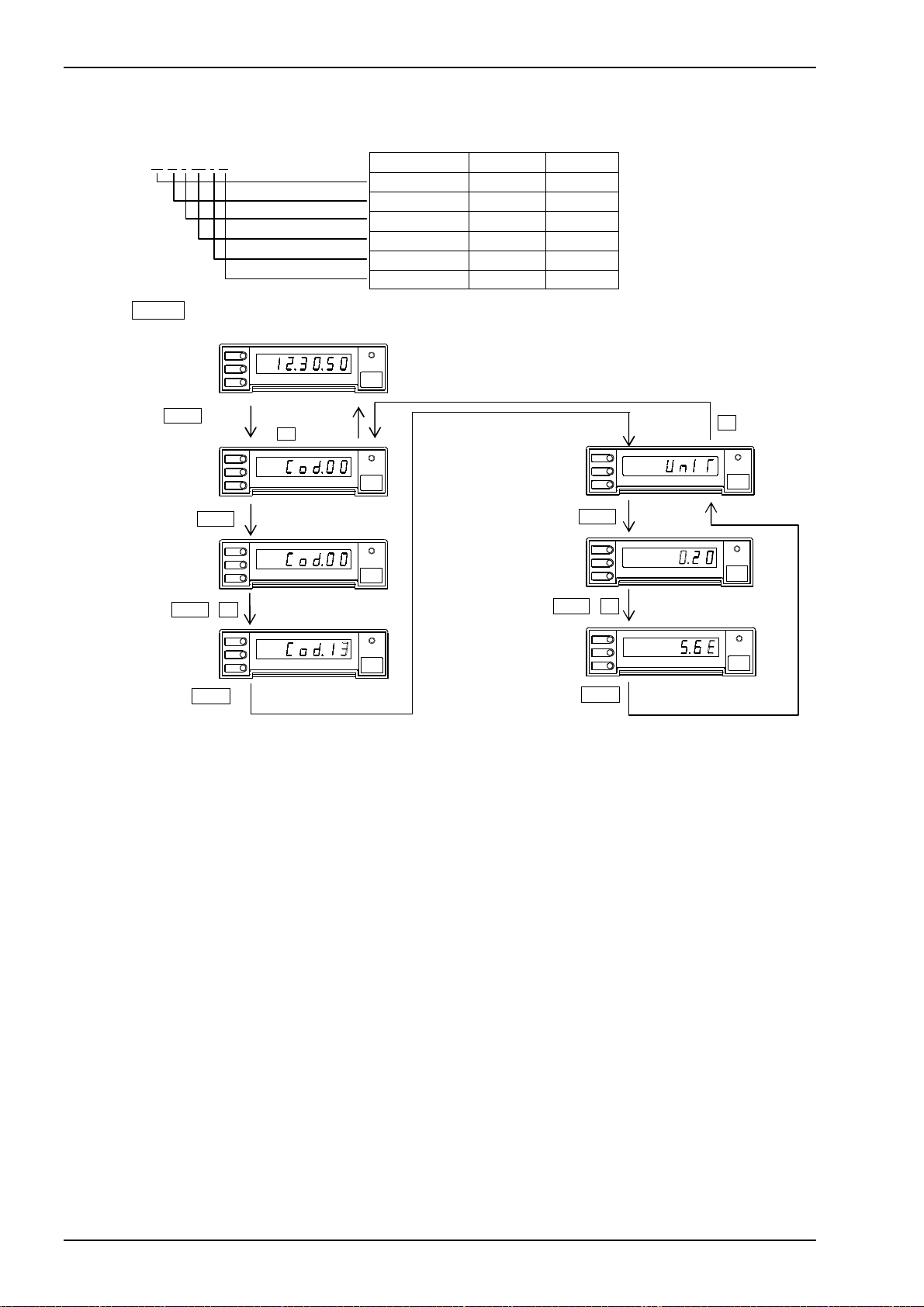
MODEL 442B
5.3.13 Unit
Example) Changing “without unit” to “kL/min”.
K L / m i n
Press MODE key for 1 sec. or more during operation to get setting mode (Display:
In operation
MODE
SHIFT
MODE 1 sec
MODE
SHIFT
UP
UP
MICRO PRINTER MOD EL 442B
Memorized by
UP Key
MICRO PRINTER MOD EL 442B
SHIFT
Setting code No.13
to change
MODE
SHIFT
MICRO PRINTER MOD EL 442B
UP
SHIFT , UP
MODE
SHIFT
MODE
MICRO PRINTER MODEL 442B
UP
Unit position Set.Code Example
1st digit 6B
2nd digit 4C
3rd digit 2F
4th digit 6D
5th digit 69
6th digit 6E
POWER
FEED
POWER
FEED
POWER
FEED
POWER
FEED
Back to Cod.00 by code No. to be set.
Code 13
Unit setting
SHIFT , UP
MODE
SHIFT
UP
SHIFT
MODE
SHIFT
UP
MODE
SHIFT
UP
MODE
MICRO PRINTER M ODEL 442B
MICRO PRINTER MODE L 442B
MICRO PRINTER MODEL 442B
)
UP
POWER
FEED
POWER
FEED
POWER
FEED
20
TSURUGA ELECTRIC CORPORATION
Page 23
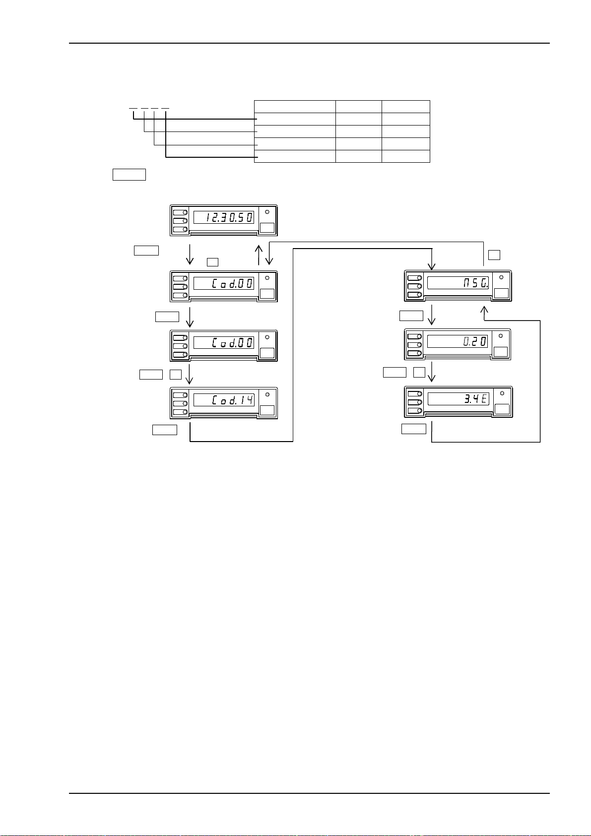
5.3.14 Message
Example) Adjusting “without message” to “OPEN”.
O P E N
Press MODE key for 1 sec. or more during operation to get setting mode (Display:
In operation
MODE
SHIFT
MODE 1 sec
MODE
SHIFT
UP
UP
MICRO PRINTER MOD EL 442B
Memorized by
UP Key
MICRO PRINTER MOD EL 442B
Setting code No.14
to change
SHIFT
MODE
SHIFT
MICRO PRINTER MOD EL 442B
UP
SHIFT , UP
MODE
SHIFT
MODE
MICRO PRINTER MODEL 442B
UP
Character position Set.Code Example
1st digit 4F
2nd digit 50
3rd digit 45
4th digit 4E
POWER
FEED
Back to Cod.00 by code No. to be set.
Code 14
POWER
FEED
POWER
FEED
POWER
FEED
Message s etting
MODE
SHIFT
UP
SHIFT
MODE
SHIFT
UP
SHIFT , UP
MODE
SHIFT
UP
MODE
MICRO PRINTER M ODEL 442B
MICRO PRINTER MODE L 442B
MICRO PRINTER MODEL 442B
MODEL 442B
)
UP
POWER
FEED
POWER
FEED
POWER
FEED
TSURUGA ELECTRIC CORPORATION
21
Page 24
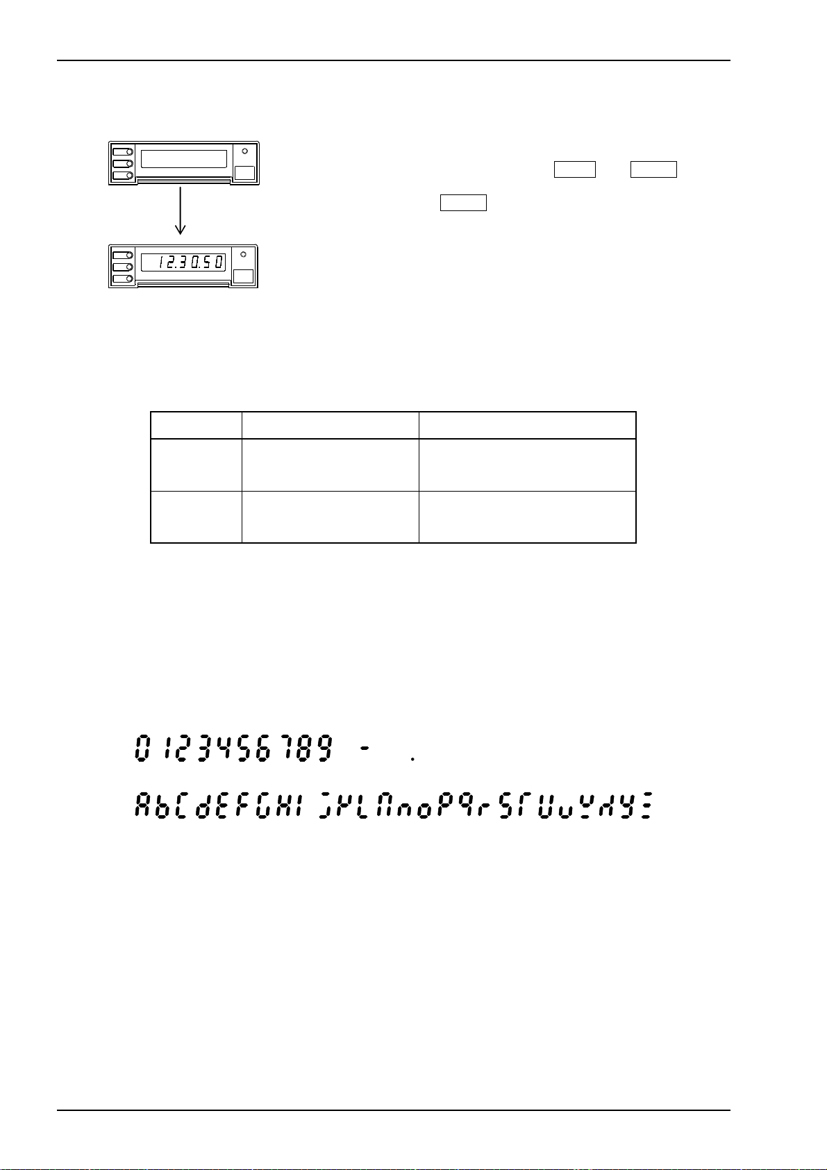
MODEL 442B
5.4 Reset to factory setting
MODE
SHIFT
UP
MODE
SHIFT
UP
Power OFF
MICRO PRINTER MODEL 442B
MICRO PRINTER MODE L 442B
POWER
FEED
POWER
FEED
5.5 Error message
Display Root Cause Measures
Turn power on while pressing both FEED and MODE key for
test rinting.
Keep on pressing MODE key till test printing is completed.
After the test printing is completed, the message “FACTORY
SETTING” is printed, of which means the product is reset.
See 5.1 Summary of function in the detail of factory setting.
Calendar clock is not initialized.
Note: During setting mode, the mode turns to operation mode automatically.
if no key operation is done for more than 5 min.
In this case, each parameter to be changed/adjusted is not memorized.
5.6 LED display
10 23456789
ABCDEFGHIJKLMNOPQRSTUVWXYZ
The code No. to be set
is not in function.
The parameter to be set
is not correct.
minus DP
See 5.1 Summary of function,
and use correct code No..
See 5.1 Summary of function,
and use correct parameter.
22
TSURUGA ELECTRIC CORPORATION
Page 25
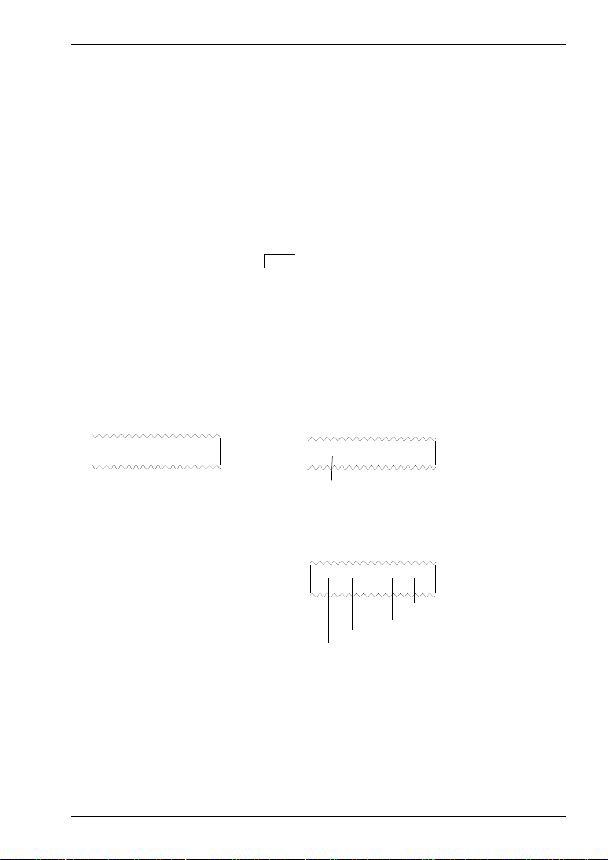
6.Printing and function
6.1 Interval
● Interval OFF
By inputting PRINT
By inputting TIME
time are printed. If PRINT
――――――
TIME
signal is given priority to PRINT
● Interval ON
By inputting PRINT
operation is started. Afterward, BCD data is being collected and printed every Interval time.
During Interval operation, PRINT
Paper feeding is available by using FEED Key or FEED input.
By inputting RESET
Index No. and Elapsed time are reset, as well.
Note) At Interval time is being 00:00:01, the sum of SYNC
should be within 1 sec.
――――――――
――――――
signal, BCD data is collected and printed.
signal, the setting information for Index No., Calendar clock ,and Elapsed
――――――――
and TIME
――――――
――――――――
signal are inputted at the same time,
signal.
――――――――
signal, BCD data is collected. Then, the data is printed and Interval
――――――――
――――――――
Key, Interval operation is released. By inputting RESET
――――――
and TIME
signal are not accepted.
――――――――
signal,
―――――――
signal L time and Printing time
6.2 Printing
6.2.1 Printing format
● At Interval operation ON
23:59:59
CH99 OR - 1.2345678kg/m
● CH No. printing.
CH No. is printed when CH No. printing is set.
0
CH No. signal (CHNo.10
, CHNo101) prints 00 to 99.
● At Interval operation OFF
――――――
TIME
signal printing
23.59.59
Printing the setting information of index No.
Calendar clock, and elapsed time printing.
――――――――
PRINT
signal printing
CH99 OR - 1.2345678kg/m
Unit
BCD data
Message
CH No.
MODEL 442B
TSURUGA ELECTRIC CORPORATION
23
Page 26
MODEL 442B
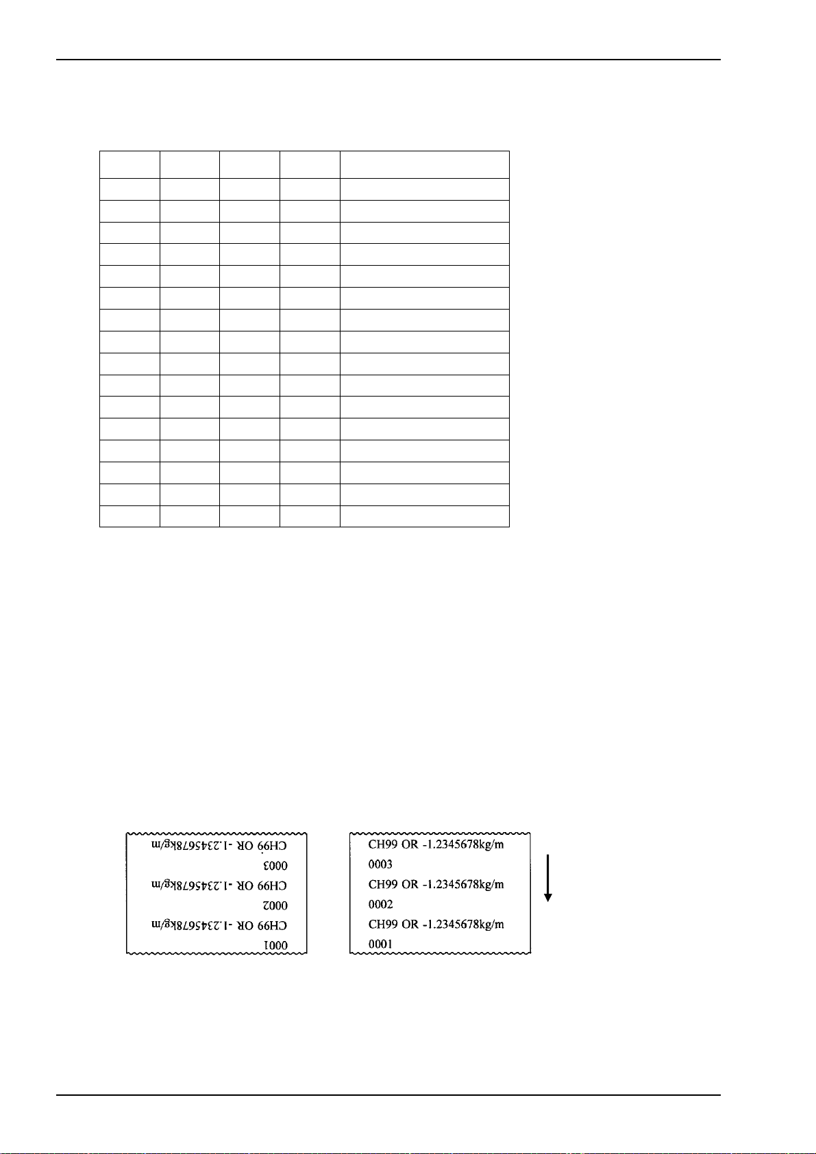
● Message printing
The message to be printed is selected by MSG Input (MSG8, MSG4, MSG2, and MSG1 signal).
The registered message can be printed, as well.
MSG8 MSG4 MSG2 MSG1 Type of message
0 0 0 0
0 0 0 1 OR
0 0 1 0 OVER
0 0 1 1 HI
0 1 0 0 HIGH
0 1 0 1 LO
0 1 1 0 LOW
0 1 1 1 GO
1 0 0 0 GOOD
1 0 0 1 NG
1 0 1 0 H NG
1 0 1 1 L NG
1 1 0 0 OK
1 1 0 1
1 1 1 0 *
1 1 1 1 Registered message
● Unit printing
Unit Input (UNIT 0 to 7 signal) selects type of Unit to print.
(refer to 6.2.4 Character code and unit table)
Reg i ste red U n it, when UNIT 0 to 7 is 11111111, is p rint e d.
● Blank line printing
Blank line setting inserts numbers of blank lines to be set after printing BCD data.
To insert blank line by printing via TIME
――――――
signal is unavailable.
6.2.2 Upright/Inverted printing
Selecting Upright or inverted printing.
Upright printing Inverted printing
Paper feed direction
24
TSURUGA ELECTRIC CORPORATION
Page 27
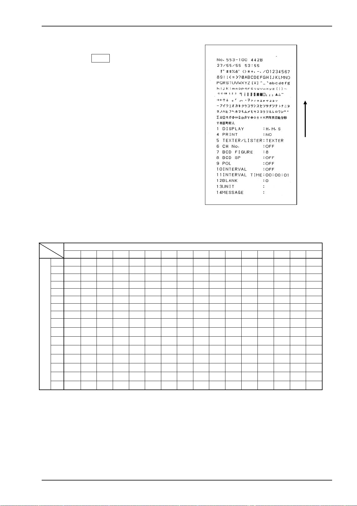
6.2.3 Tes t printin g
Printing sample
Test printing starts by supplying power while
pressing FEED Key.
After Test printing is completed, the product
backs to normal operation condition.
Test printing prints Test Pattern and Setting
status.
6.2.4 Character code and unit table
■ Character code table
High order bit
0 1 2 3 4 5 6 7 8 9 A B C D E F
0 SP 0 @ P ` p
1 ! 1 A Q a q
2 ” 2 B R b r
3 # 3 C S c s 0 ▲ 」 ウ テ モ π 月
4 $ 4 D T d t 1 △ 、 エ ト ヤ σ 日
5 % 5 E U e u 2 - ・ オ ナ ユ φ 時
6 & 6 F V f v
7 ’ 7 G W g w ゜
8 ( 8 H X h x
9 ) 9 I Y i y
Low order bit
A *: J Z j z
B +; K [ k {
C ,< L ¥ l |
D -= M ] m }
E .> N ^ n ~
F /? O _ o
-1
-2
-3
3
■
□
SP ー タ ミ Σ ×
1
。 ア チ ム μ 円
2
「 イ ツ メ Ω 年
3
ヲ カ ニ ヨ ∞ 分
キ ヌ ラ ℓ 秒
ア
→
←
↑
↓
ク ネ リ α 〒
イ
ケ ノ ル β 市
ウ
コ ハ レ γ 区
エ
サ ヒ ロ 町
オ
シ フ ワ ● 村
ヤ
ス ヘ ン ○ 人
ユ
セ ホ ゛ ±
ヨ
ソ マ ゜ ÷
ツ
SP means “space”.
MODEL 442B
Paper feed direction
TSURUGA ELECTRIC CORPORATION
25
Page 28

MODEL 442B
■ Unit table The following is Unit to be set by UNIT 0 to 7
UNIT
76543210
00000000
00000001
00000010
00000011
00000100
00000101
00000110
00000111
00001000
00001001
00001010
00001011
00001100
00001101
00001110
00001111
00010000
00010001
00010010
00010011
00010100
00010101
00010110
00010111
00011000
00011001
00011010
00011011
00011100
00011101
00011110
00 011111
%CO
%O
2
%RH
A/m
2
A/m
A・h
C/mol
Ci
C・m
F/m
GHz
H/m
HP
Hz
3
J/m
MHz
MPa
MW
Mvar
MΩ
MΩ/cm
MΩ・cm
N/m
2
N/m
3
/h
Nm
N・m
MN
2
N/mm
%
O
2
Unit
UNIT
76543210
00100000
00100001
00100010
00100011
00100100
00100101
00100110
00100111
00101000
00101001
00101010
00101011
00101100
00101101
00101110
00101111
00110000
00110001
00110010
00110011
00110100
00110101
00110110
00110111
00111000
00111001
00111010
00111011
00 11110 0
00 11110 1
00 111110
00 111111
Pa
Pa・s
S/m
VA
VU
2
W/m
Wb
W・h
W・s
atm
bar
cal
cc
cc/min
cd
2
cd/m
cm
cm/min
cm/s
2
cm
cpm
cps
dB
deg
dps
eV
Unit
UNIT
76543210
01000000
01000001
01000010
01000011
01000100
01000101
01000110
01000111
01001000
01001001
01001010
01001011
01001100
01001101
01001110
01001111
01010000
01010001
01010010
01010011
01010100
01010101
01010110
01010111
01011000
01011001
01011010
01011011
01011100
01011101
01011110
01 011111
feet
g/cc
3
g/cm
g/h
g/l
g/min
2
g/m
-1
h
inch
kA
kHz
kPa
kV
kW
kcal
kg
kg/h
kg/l
kg/m
kg/min
kg/m3
kg/s
kN・m
kN/cm2
kl
Unit
UNIT Unit UNIT Unit UNIT Unit UNIT Unit
10000000
10000001
10000010
10000011
10000100
10000101
10000110
10000111
10001000
10001001
10001010
10001011
10001100
10001101
10001110
10001111
10010000
10010001
10010010
10010011
10010100
10010101
10010110
10010111
10011000
10011001
10011010
10011011
10011100
10011101
10011110
10 011111
mg/l
min
-1
min
ml/min
mm
mm/min
mm/s
2
mm
mol
mol/l
3
mol/m
-1
mol
ms
-1
m
2
m
2
/s
m
3
m
3
/d
m
3
/h
m
3
/min
m
3
/s
m
mΩ
nA
pA
pF
pH
pW
phon
ppb
10100000
10100001
10100010
10100011
10100100
10100101
10100110
10100111
10101000
10101001
10101010
10101011
10101100
10101101
10101110
10101111
10110000
10110001
10110010
10110011
10110100
10110101
10110110
10110111
10111000
10111001
10111010
10111011
10 11110 0
10 11110 1
10 111110
10 111111
ppm
rad
rad/s
rem
rph
rpm
rps
sec
-1
s
ton
t/h
t/min
t/s
var
℃
Ω・m
Ω・cm
μA
μF
μS/cm
μSv/h
μV
μW
μm
μs
μΩ
μΩ・cm
11000000
11000001
11000010
11000011
11000100
11000101
11000110
11000111
11001000
11001001
11001010
11001011
110 01100
110 01101
11001110
110 01111
11010000
11010001
11010010
11010011
11010100
11010101
11010110
11010111
11011000
11011001
11011010
11011011
11011100
11011101
110 11110
110 11111
a
b
c
d
e
f
g
h
i
j
k
l
m
n
o
p
q
r
s
t
u
v
w
x
y
z
゚
′
″
μ
Note) Character and Unit style may be different from the ones in the table above due to printing condition.
UNIT
76543210
01100000
01100001
01100010
01100011
01100100
01100101
01100110
01100111
01101000
01101001
01101010
01101011
01101100
01101101
01101110
011 01111
01110000
01110001
01110010
01110011
01110100
01110101
0111 0110
0111 0111
01111 000
01111 001
01111 010
01111 011
011111 00
011111 01
0111111 0
01111111
11100000
11100001
11100010
1110 0011
11100100
11100101
11100110
1110 0111
11101000
11101001
11101010
1110 1011
11101100
11101101
11101110
1110 1111
11110 000
11110 001
11110 010
11110 011
11110 100
11110 101
11110110
11110 111
111110 00
111110 01
111110 10
111110 11
1111110 0
1111110 1
11111110
11111111
Unit
kl/h
km
km/h
kN
kvar
kΩ
kΩ/cm
l/h
l/min
l/s
lb
lm
lm/W
2
lm/m
lm・s
lx
lx・s
m/h
m/min
m/s
2
m/s
mA
mN
mF
mS/cm
mSv/h
mV
mW
mg
mg/h
%
A
B
C
D
E
F
G
H
I
J
K
L
M
N
O
P
Q
R
S
T
U
V
W
X
Y
Z
分
Ω
Registered Unit
26
TSURUGA ELECTRIC CORPORATION
Page 29
MODEL 442B
p
p
g op
6.3 Error
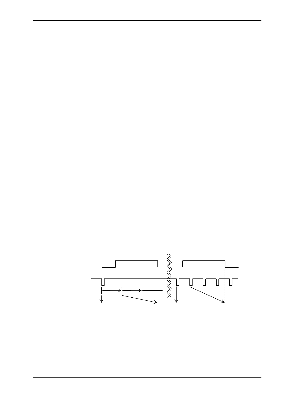
6.3.1 Paper end detection
Paper end detection sensor is incorporated to detect paper end.
PE output (“H”) is provided at no paper, and in this case the printing is unavailable.
POWER LED is blinking.
The previous one cycle data just before paper end is printed out after resetting
paper end. (Refer to Timing Chart below)
6.3.2 Temperature error detection
The printing is unavailable when the temperature of Printer Head reach to 80℃ or more.
Then, the printer dose not work till the temperature falls to 60℃ or less.
POWER LED is blinking.
The previous one cycle data just before temperature error is printed out after resetting
temperature error. (Refer to Timing Chart below)
6.3.3 Synchronized signal error detection
When SYNC
is printed out, and POWER LED is blinking.
BUSY output and RESET
―――――――
signal is at L level for approx. 1 sec. or longer, “ERROR SYNC LOW LEVEL”
――――――――
input resets this error.
Only paper feeding is available.
6.3.4 Low voltage alarm (backup battery for calendar clock)
When battery power is lower than the normal working level, following messages would be
printed when supplying the power: “ERROR”, “BATTERY LOW LEVEL”. Once those
alarms are displayed, the calendar clock might be in abnormal status. We recommend you
to replace batteries as soon as possible. Ask our distributors or our sales team to
replacement details.
● Timing chart
Paper end
erature error
Tem
――――――――
PRINT
Interval time
Printin
eration
Printing
Interval operation ON
Error
Interval o
Printing Printing Printing
eration OFF
Error
TSURUGA ELECTRIC CORPORATION
27
Page 30
MODEL 442B
7. Specification
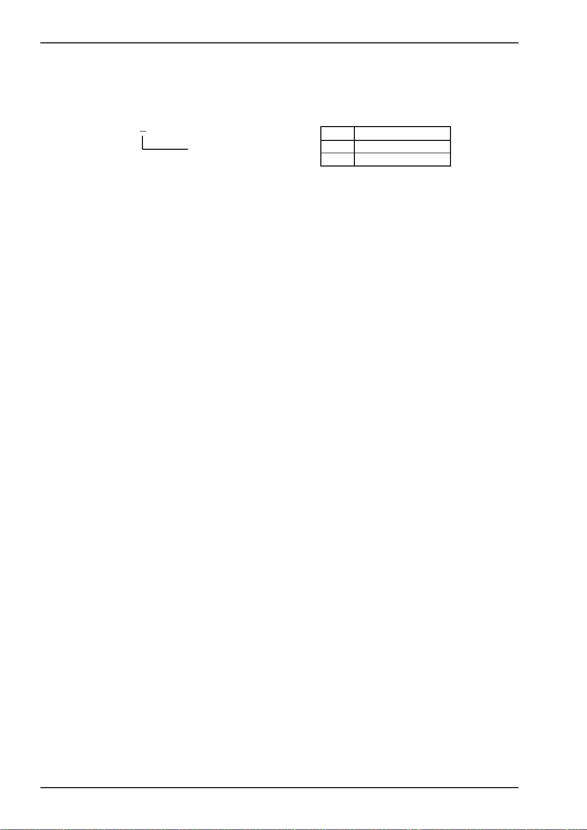
7.1 Model
442B-□
1
Power supply
[ 1 ] Power supply
Code Power Supply
A 100 to 240V AC
9 24V DC
7.2 Performance
Power supply: 100 to 240V AC 50/60Hz, 24V DC.
Power range: 90 to 250V AC, 21.6 to 26.4V DC.
Power consumption: Approx.15VA (at printing) / approx. 3.2VA (at waiting) at100V AC.
Approx.16VA (at printing) / approx. 5VA (at waiting) at 200V AC.
Approx.500mA (at printing) / approx. 55mA (at waiting) at24V DC.
Operating temperature: 0 to 50 ℃
Operating humidity: 85% RH or less (no condensation)
Storage temperature: -20 to 60 ℃
Weight: Approx. 700g (350g : attached connector)
Installation: Panel mounting
7.3 General
Dielectric strength: Input/Output – Power 1500V AC. For 1min. (AC powered)
500V AC. For 1min. (DC powered)
Insulation resistance: Input/Output – Power 500V DC, 100MΩ or more. (AC powered)
500V DC, 50MΩ or more.(DC powered)
28
TSURUGA ELECTRIC CORPORATION
Page 31
MODEL 442B
7.4 Printer
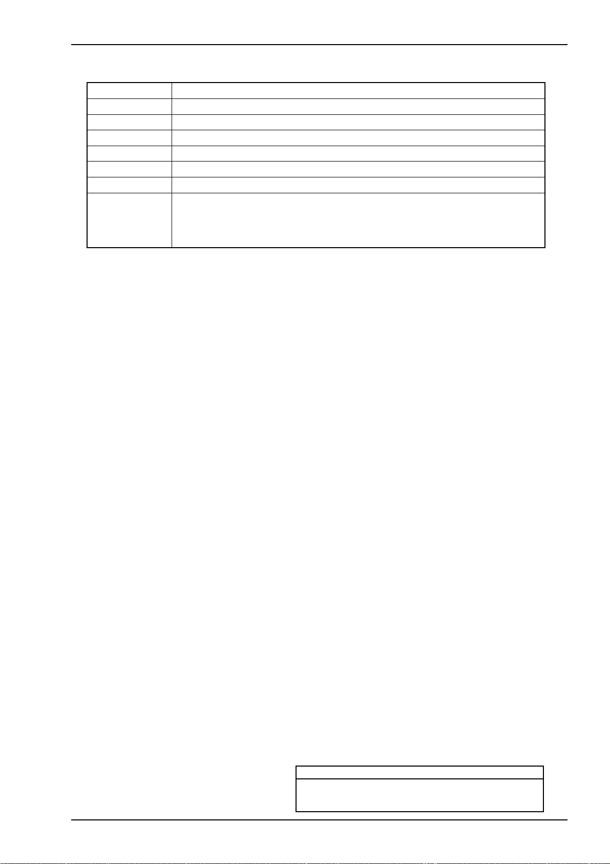
Print style Thermal line dot.
Character Alphabet, Numbers, Katakana, Symbols, etc.
Dot 16x16 (2mmx2mm)
Line 24 lines, Max.
Printing speed Approx. 22.5mm/sec, 6 lines/sec., Max. Note) Printing rate 16% or less.
Paper feeding 3.75mm pitch.
Printing width 46mm
Life time
At 25 ℃
Head: 109 pulse or more (pulse resistance)
50km or longer except damage by foreign particle, alien substance.
(abrasion resistance)
7.5 Chart roll paper
Paper: 58mm width x 48φ(inside diameter 12φ)
Length 25m (approx. 6500 lines printable)
Use specified chart paper, otherwise printing quality and products lifetime will be
out of warrantee.
Sold separately
5860-01 Chart paper (10 rolls)
7.6 Calendar clock
Display: 6 digits red LED Hour, Minute, Second.
Accuracy: ±3 sec. per day. (at 25℃)
A leap year adjustment: Automatic adjustment till 2099.
Power failure measure: Calendar clock works.
(Battery life approx. 10 years.)
Contact Information
Name : Tsuruga Electric Corporation
Address : 1-3-23 Minami-Sumiyoshi, Sumiyoshi-ku, Osaka-shi
558-0041 Japan
TSURUGA ELECTRIC CORPORATION
29
 Loading...