

Page 1
Instruction Manual
Digital Large Display Meter, Model 4021
I-01950
1. Preface
● Please take care that this instruction manual is certainly delivered to the person in charge of operating this instrument.
● Unpack the product and confirm that the following items are included.
(1) 4021 itself (2) Instruction manual (3)CJS (for thermocouple only. It is installed in the terminals)
For safety and proper use of this product, please observe the following caution and also read the instruction manuals to follow before
the initial operation.
CAUTION
● The 4021 becomes active as soon as it is connected to a power source.
It has no On or Off switch. But warm-up time is necessary at least 15 minutes.
● Do not install under the following conditions.
-Where it is exposed to direct sunlight, dust, corrosive gases, rain, etc.
-Where ambient temperature or humidity is high.
-Where it is exposed to excessive noise or static electricity.
-Where there is constant vibration or shock
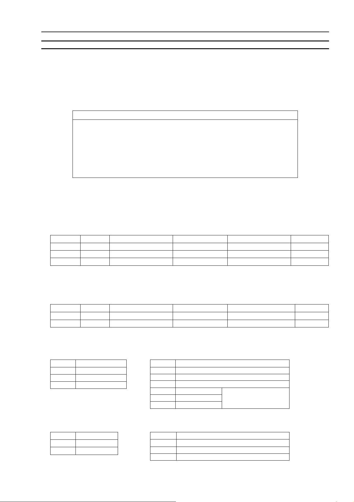
2. Standard Specifications
2.1 Model Name
4021 – □ – □ – □ – □ – □
( 1 ) ( 2 ) ( 3 ) ( 4 ) ( 5 )
(1) Measuring Input
[ Thermocouple input ]
Model Sensor Measuring range
4021-02 K -200 〜 999 oC -270 〜 999
4021-04 J -200 〜 999 oC -210 〜 999
4021-05 T -200 〜 400 oC -270 〜 420
< NOTE > Accuracy: Defined at 23
Temperature coefficient: ±300ppm/
Compensation of standard contact: ±1
Calibration: In conjunction with JIS C 1602-1995, by each standard thermoelectric power mV input.
[ RTD input ]
Model Sensor Measuring range
4021-11 Pt100Ω -200 〜 850 oC -200 〜 870
4021-12 Pt100Ω -99.9 〜 99.9 oC -99.9 〜 99.9
< NOTE > Accuracy: Defined at 23
Temperature coefficient: ±200ppm/
Calibration: In conjunction with JIS C 1604-1997, by the resistive value of standard resistive elements.
(2) Power Supply
No. Power
3 AC100 〜 120V
5 AC200 〜 240V
9 DC 24V
(4) Color
No Type
(Null) Red LED
G Green LED
o
C±5oC, 45 to 75%RH.
o
C±5oC, 45 to 75%RH.
o
C within the 0 to 50oC temperature range.
o
C within the 0 to 50oC temperature range.
o
C within the 0 to 50oC temperature range.
(3) Mounting
No. Type
51 Wall-mount
52 Hanging-mount
53 Sticking-mount
61 Wall-mount
62 Hanging-mount
63 Sticking-mount
(5) Option
No. Function
(Null) Peak Hold
A01 Bottom Hold
A02
<NOTE>: Thermocouple input only.
Change of the burnout direction <NOTE>
Display range
Display range
o
C ±(0.3% of rdg +1oC) DC±10 V
o
C ±(0.3% of rdg +1oC) DC±10 V
o
C ±(0.3% of rdg +1oC) DC±10 V
o
C ±(0.4% of rdg +1oC) DC±10 V
o
C ±(0.2% of rdg +0.3oC) DC±10 V
Accuracy <Note> Overload
Accuracy <Note> Overload
Integral Pt sensor
(for RTD input only)
-1 -
Page 2

2.2 General Specifications
Display : Red or Green LED (character height 56mm) with zero-suppress function.
Over-range indication : Flashes at minimum or maximum value of the display range when exceeding.
Burnout : Blinking with maximum value of display range.
Hold Function : Measured data is held (Not isolated from input).
Peak Hold : Maximum value of the measured data is held (Not isolated from input).
o
Resolution : Thermocouple input; 1
o
RTD input; 1
C (-11) or 0.1oC(-12)
C
Allowable external resistance : Thermocouple input; 500Ω or less
RTD input; 5Ω or less / lead wire (resistance value of 3 wires shall be same)
Display Cycle : Approx. 200ms
Input Type : Single ended
A/D Conver sion : ∆-Σ conversion system.
Noise Rejection : Normal mode (NMR) - 50dB or more.
Common mode (CMR)-110dB or more.
Noise through power supply line
: 1000V
Insulation Resistance : Input terminals – Case : DC500V 100MΩ or more.
Power terminals – Case : DC500V 100MΩ or more.
Power terminals - Input terminals : DC500V 100MΩ or more.
Withstanding Voltage : Input terminals – Case : AC1500V each for 1 min.
Power terminals – Case : AC1500V each for 1 min.
Power terminals - Input terminals : AC1500V each for 1min.
(in case of DC power supply, AC 500V each for 1 min.)
Power Supply : AC100 to 120V 50/60Hz, AC200 to 240V 50/60Hz, DC24V
Allowable power : AC85 to 132V 50/60Hz, AC170 to 250V 50/60HZ, DC20 to 30V
Power Consumption : Approx. 6VA at AC100V, Approx.10VA at AC200V, Approx.100mA at DC24V
o
Operating Temperature : 0 to 50
Storage Temperature : -20 to 70
C
o
C
Weight : Approx. 1.6kg
o
Unit :
C
Protection : IP44 (Wall-mount and hanging-mount)
IP65 (Sticking-mount with water-proof works)
2.3 Optional specifications
● Bottom Hold function
Display the minimum value of the measured data (Not isolated from input).
In this case, Peak Hold function is disabled.
● Change of the burnout direction
It is Available to flash the minimum value when using the thermocouple input.
Model 4021
-2 -
Page 3
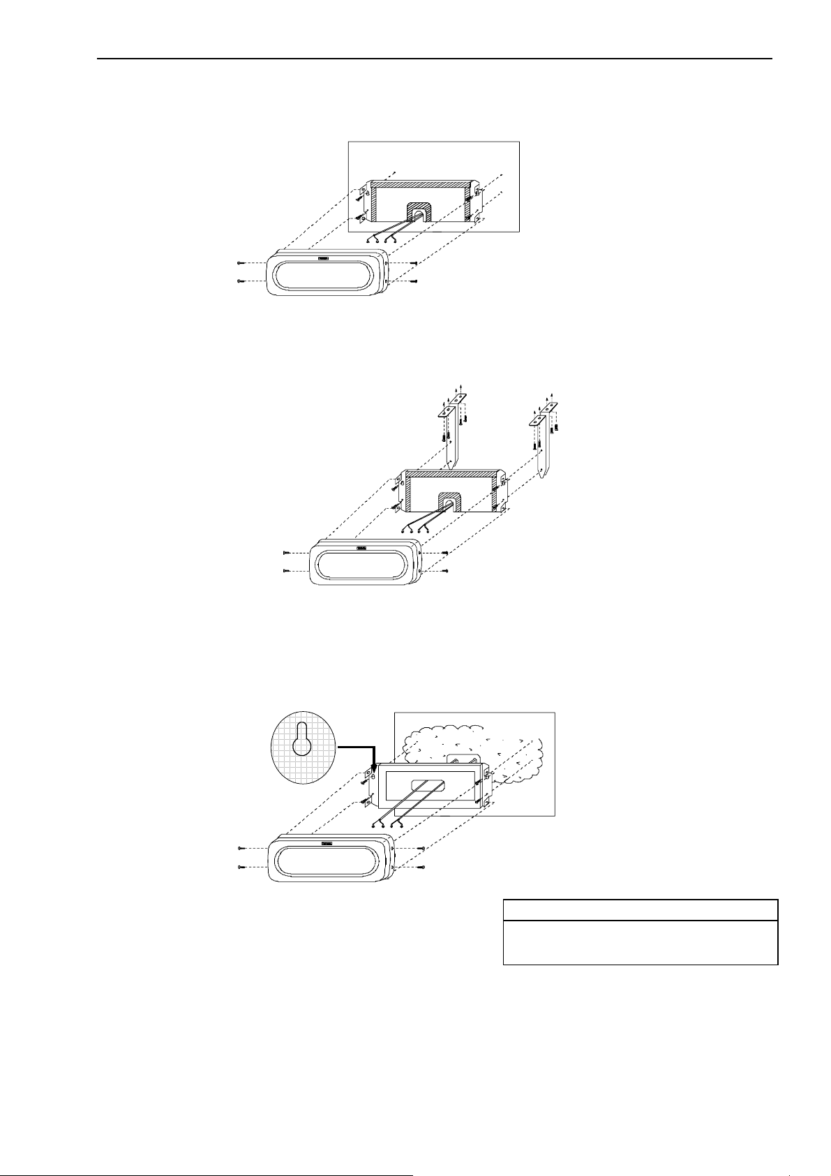
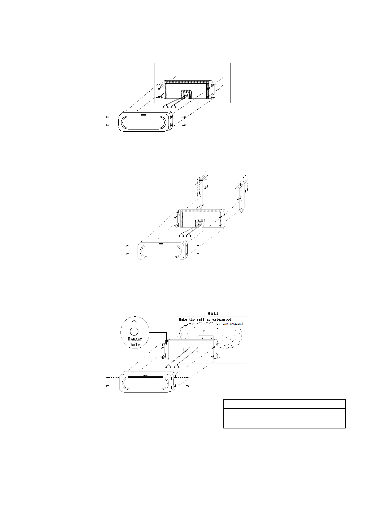
2.4 Mounting
●Wall-mount (model code-51)
NOTE: Cut the case bottom or side to pull out lead wires.
●Hanging-mount (model code-52)
NOTE: Fixing points should be locating 10mm away from the wall.
●Sticking-mount (model code-53)
NOTE: Use coaching bond or appropriate sealant to keep IP65 protection.
Hanger
hole
Wall
Make the wall in waterproof
Model 4021
Mount to the top roof
Wall
by the sealant
CAUTION
・Hanger hole of the mounting panel should be
upright position as shown in the drawing.
-3 -
Page 4
Model 4021
3. Setting of Each Function
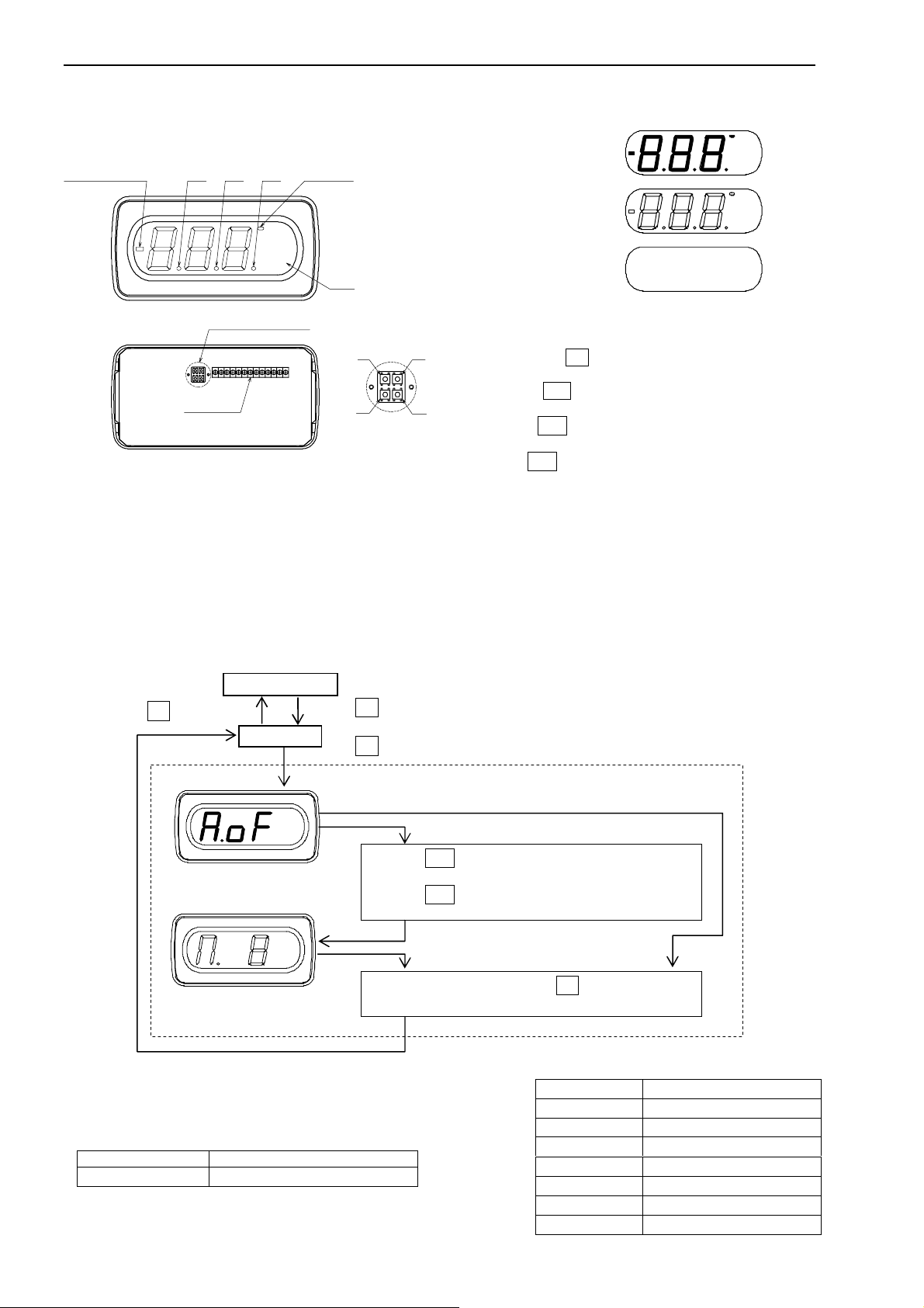
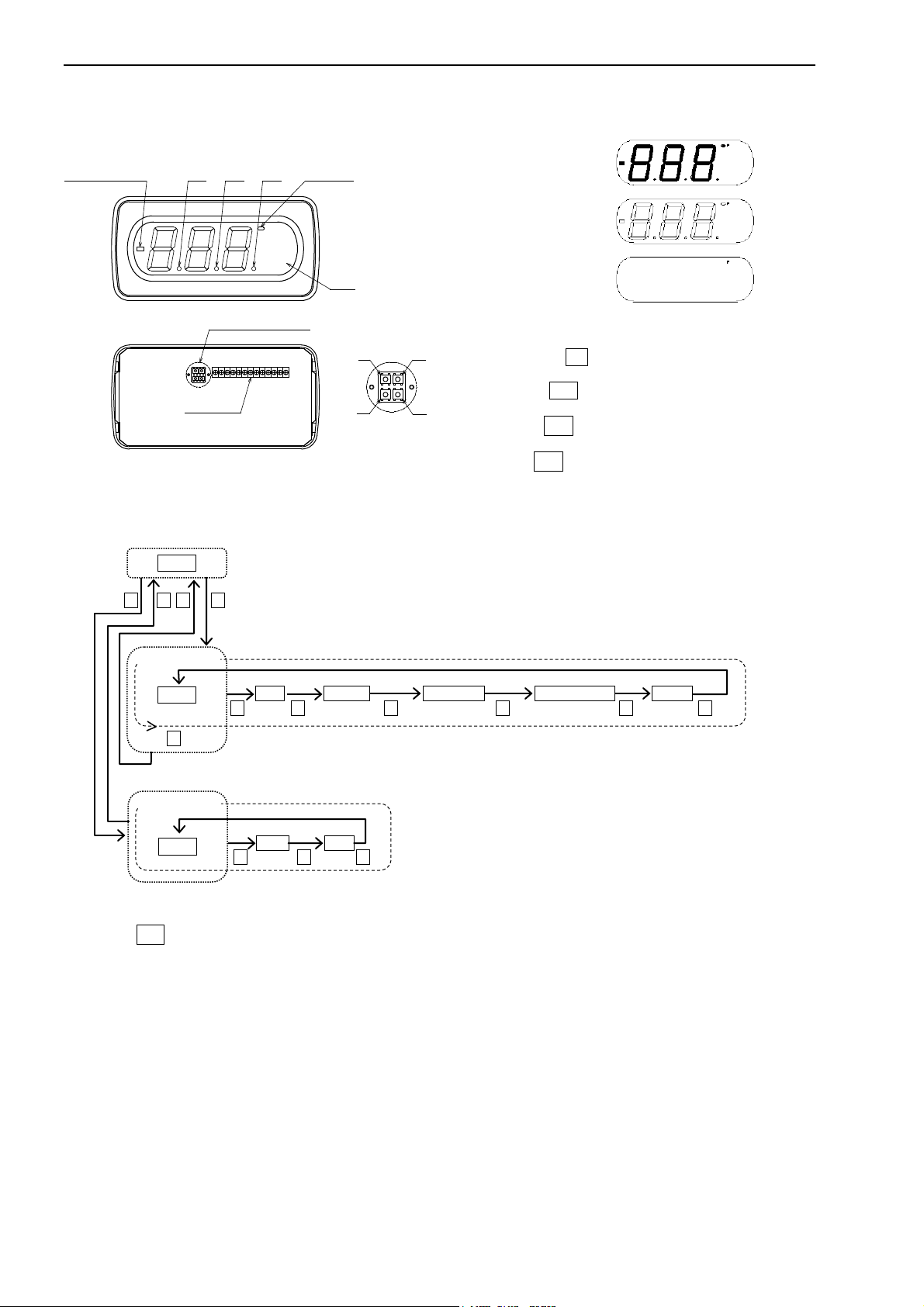
● Name of each part
DP0DP1DP2
P
PH LEDPolarity LED
(BH LED)
℃
Unit
Setting switch※
※
Terminals
>
● Setting mode
- Changes to the settings are saved to EEPROM when returning to the measuring mode. Display temporally turns off the light
- Once flashing the new setting value in the setting mode, it is saved into the memory, and peak value (or bottom value) goes clear.
- If you do not touch any switch for 5 minutes at the setting mode, it automatically returns to the measuring mode without saving
changes.
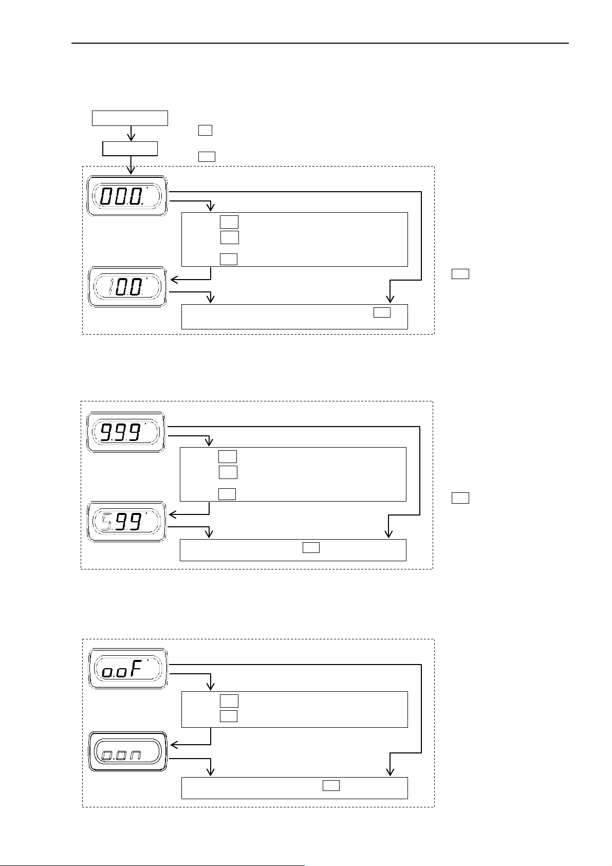
3.1 Setting method
3.1.1 Average operation
Average operates the interval average or the moving average.
Example) Changes the non-average operation to the moving average of 8-data.
F switch
- Since the interval average operates 6-data, display cycle is approx. 1.2s.
- In case of moving average, display cycle is approx. 200ms.
[ Default ]
Function Setting value
Average operation
Measuring mode
F switch Approx. 3 sec.
P
M switch
℃
Push the > switch to move to the setting mode.
Push the Λ switch to set the average calculation
value.
P
℃
Exit this parameter by pressing M switch and display
Enable Interval average
Display the existing value
● Display
Lit-up display
Blinking display
Turned-off display
● Function of each switch
MF
Functions switch F : Change between the measuring
mode and the setting mode.
Mode switch M : Change parameter item at the setting
∧
mode.
Shift switch > : Move to the next action or shift the
value.
Up switch ∧ : Scroll or increase the value or figure
(Blinking display)
[ Contents of average operation ]
Display Contents
Without average operation
Interval average
Moving average, 2-time
Moving average, 4-time
Moving average, 8-time
Moving average, 16-time
Moving average, 32-time
P
P
P
Setting mode
-4 -
Page 5
4. Wiring
● Do not miswiring. Otherwise, the meter is broken.
● To avoid an electrical shock, turn the power off when wiring.
● Do not wire with moistened hands. Locate away from the wet place.
● Do not touch terminals when turning the power on.
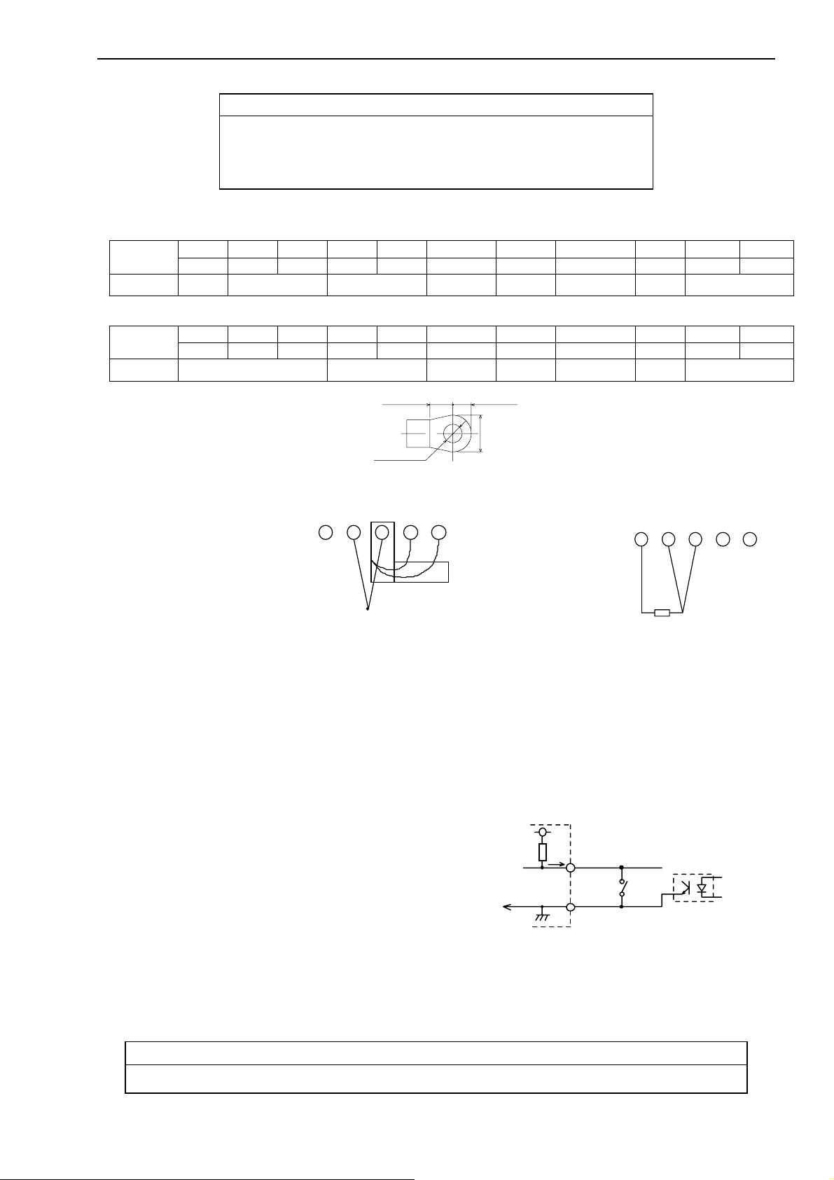
4.1 Terminal Arrangement
[ Thermocouple input ]
Terminal
Function
[ RTD input ]
Terminal
Function Input
Terminal screws: M3
Fastening torque: 0.46~0.62N m
Crimp terminal: As shown on the right.
NC + - CJS+ CJS- COM HOLD
1 2 3 4 5 6 7
−
Input CJS Common Hold Peak Hold
A B B NC NC COM HOLD
1 2 3 4 5 6 7
CAUTION
−
5.3min.
φ3.2min.
Common Hold Peak Hold − Power supply
4.4max.
6max.
PH
8
PH
8
Model 4021
NC P2(+) P1(-)
9 10 11
−
Power supply
NC P2(+) P1(-)
9 10 11
● Input terminals
[ Thermocouple input ]
Pay attention to the polarity when wiring.
CJS is not compatible.
Make sure that the serial number
of the CJS and the meter must match.
● Hold (HOLD)
+
NC
1
−
+
−
Thermocouple
42
Purple
CJS−CJS+
53
Gray
CJS
[ RTD input ]
Connect 3-wire of the RTD.
A
1
RTD
B
B
32
NCNC
4 5
Display can be held by connecting the Hold terminal and the Common terminal.
Active “L” I
IL≦-1mA, “L”=0 to 0.8V, “H”=3.5 to 5V
● Peak Hold (PH)
Maximum value is displayed by connecting the Peak Hold terminal and the Common terminal. “PH” and LED are lit during the
peak hold function. This function is released by disconnecting the PH terminal.
Active “L” I
IL≦-1mA, “L”=0 to 0.8V, “H”=3.5 to 5V
● Bottom Hold (PH)
If your meter code is –A01, PH terminal is for the bottom hold. Minimum value is displayed by connecting the Peak Hold terminal
and the Common terminal. “BH” and LED are lit during the bottom hold function. This function is released by disconnecting the
PH terminal.
Active “L” I
IL≦-1mA, “L”=0 to 0.8V, “H”=3.5 to 5V
+5V
● Common (COM)
“COM” terminal is used for Hold and Peak (or Bottom) Hold terminals.
NOTE: Those terminals, COM, HOLD and PH, are not isolated to the input.
Use a photo-coupler or switch to insulate.
It is essential when using the input floating.
● Power Supply (P1(-), P2(+))
1mA or le
IN Lo
4021
D
HOL
COM
swi t ch
s s
ph o to‑coupler
The power supply voltage is specified on the terminal plate at delivery from our factory.
- AC power supply(3): Use the meter within the range AC85 to 132V.
- AC power supply(5): Use the meter within the range AC170 to 250V.
- DC power supply(9): Use the meter within the range DC20 to 30V.
Connect +24V positive of DC power to P2 (+), and 0V negative side to P1 (-).
CAUTION
● Do not use the product with the voltage out of the rated range as it may cause breakage of the products.
-5 -
Page 6
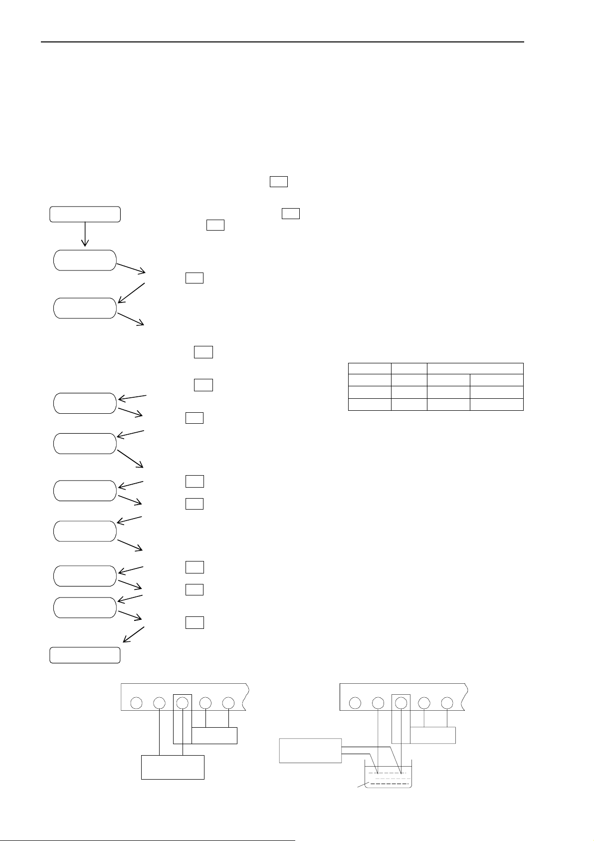
Model 4021
5. Maintenance
Store the meter within the rated storage temperature (from -20 to +70oC). When the front panel or the case is cleaned, use soft cloth
dipped with cleaner liquid. Do not use organic solvent like benzene or paint thinner as they may deform or discolor the case.
6. Calibration
In order to maintain long term accuracy, periodical calibration at an interval of about one year is recommended. Make a calibration in
the ambient condition of 23
6.1 Calibration of Thermocouple input
Prepare the standard voltage generator, cold contact circuit (ice-bath), and standard thermocouple for calibration.
To enter the calibration mode, turn the power on with pushing M switch.
Power OFF
Power OFF
o
C±5oC, 75%RH or less.
Connect the voltage generator and the CJS thermocouple as shown in the Figure-1.
Turn the power on with pushing the M switch.
Hold down the M switch for over five seconds.
After the lump test (all LED light up), display shows the sensor number, and then proceeds to the
Calibration mode with “
” message.
Press the M switch to enter ZERO and MAX calibration.
Display shows the measuring value. Resolution is 0.1
o
C.
100
o
C for 100oC or lower, and 1oC for more than
-ZERO calibration
Set the voltage generator to 0.00mV as shown in the Figure-1.
Press the > switch to momentarily memorizes the ZERO value.
- MAX calibration
Set the voltage generator to the maximum voltage.
Press the Λ switch to momentarily memorize
the MAX value. NOTE1
Press the M switch to enter GAIN calibration
of the thermocouple in the ice-bath.
Display shows the measuring value.
NOTE2
No. Sensor
NOTE1: An error message “
NOTE2: Resolution is 0.1mV for 100mV or lower,
NOTE1
MAX
K 950℃ 39.314mV
J 950℃ 54.956mV
T 400℃ 20.872mV
if you calibrate out of range.
and 1mV for more than 100mV.
” will be displayed
Set the voltage generator to 500.0mV as shown in the Figure-1.
Press the Λ switch to momentarily memorize the calibration value.
Press the M switch to enter ZERO calibration of the thermocouple in the ice-bath.
Connect the voltage generator, the CJS thermocouple, and the ice-bath as shown in the Figure-2.
Display shows the measuring value.
NOTE2
Set the voltage generator to 0.00mV.
Press the > switch to momentarily memorizes the ZERO value.
Press the M switch to show “
”
Press the Λ switch to be complete your calibration. Display flashes to confirm your calibration.
Do not turn the power off to confirm your calibration.
An error message “
” will be displayed if you calibrate out of range.
+
NC
2
1
CU+
Standard voltage
generator
CU−
−
4
53
Gray
Purple
CJS
Standard voltage
generator
NC
1
Standard
Thermocouple
CU−
CU+
−
+
2
3
4
5
−
+
Purple
CJS
Gray
Fig.‑1 Fig.‑2
-6 -
ice water 0℃
Page 7
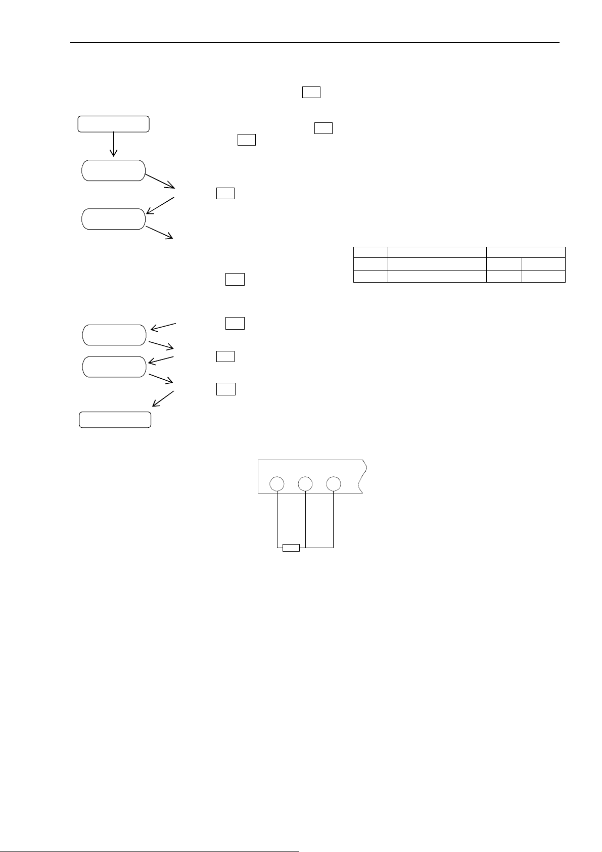
6.2 Calibration of RTD input
Prepare the standard variable resistor.
To enter the calibration mode, turn the power on with pushing M switch.
Power OFF
Power OFF
Connect the standard variable resistor as shown in the Figure-3.
Turn the power on with pushing the M switch.
Hold down the M switch for over five seconds.
After the lump test (all LED lit up), display shows the sensor number, and then proceeds to the
Calibration mode with “
Press the M switch to enter ZERO and MAX calibration.
Display shows the measuring value. Resolution is 0.1
o
C.
100
” in case of Pt100Ω (-200 to +850oC)
“
-ZERO calibration
Set the variable resistor to 100.0Ω (0.0
Press the > switch to momentarily
memorizes the ZERO value. NOTE1
- MAX calibration
Set the variable resistor to 375.70Ω (800
Press the Λ switch to momentarily memorize the MAX value.
Press the M switch to show “
Press the Λ switch to be complete your calibration. Display flashes to confirm your calibration.
Do not turn the power off to confirm your calibration.
An error message “
” message.
o
C).
o
C).
”.
” will be displayed if you calibrate out of range.
B
B
A
2
1
3
o
C for 100oC or lower, and 1oC for more than
No. Sensor (range)
NOTE1: An error message “
Pt100Ω(-200〜850℃) 800℃ 375.70Ω
Pt100Ω(-99.9〜99.9℃) 95.0℃ 136.61Ω
calibrate out of range.
NOTE1
” will be displayed if you
Model 4021
MAX
B
B
A
Standaed variable resistor
Fig.‑3
-7 -
Page 8
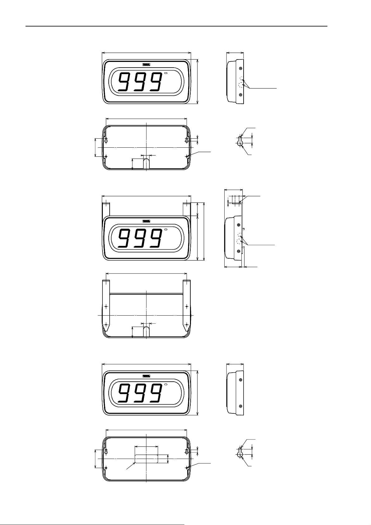
7. Dimensions
7.1 Basic type
● Wall-mount (-51)
● Hanging-mount (-52)
● Sticking-mount (-53)
55
55
Model 4021
270
P
℃
245
18
33.5
270
P
℃
245
18
33.5
270
P
℃
245
70
5
R
‑
4
25
135
8
2‑φ4.5
40
175
135
135
8
2‑φ4.5
52
R2.25
R4
55
81211
3
4‑φ4.5
Provided at both side
52 10max
52
R2.25
R4
Split‑able
Provided at both side
and bottom
8
Split‑able
and bottom
8
Unit: mm
-8 -
Page 9
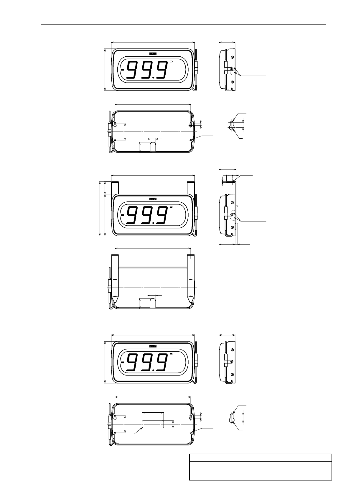
7.2 Integral Pt sensor
● Wall-mount (-61)
● Hanging-mount (-62)
● Sticking-mount (-63)
175
135
135 40
135
55
55
Model 4021
33.5
33.5
270
245
270
245
270
P
℃
8
18
P
2‑φ4.5
℃
18
P
52
R2.25
R4
55
81211
3
52 10max
52
Split‑able
Provided at both side
side and bottom
8
4‑φ4.5
Split‑able
Provided at both side
side and bottom
℃
245
R2.25
70
5
R
‑
4
25
8
2‑φ4.5
8
R4
Unit: mm
Contact Information
Name : Tsuruga Electric Corporation
Address : 1-3-23 Minami-Sumiyoshi, Sumiyoshi-ku, Osaka-shi
558-0041 Japan
-9 -
Page 10
- 1 -
Instruction Manual
CAUTION
Model
Measuring range
Input resistance
Accuracy <Note>
Overload
4022-03
± 999 mV
1MΩ
± (0. 1% of rdg +1 di git)
DC ±250 V
4022-04
± 9.99 V
1MΩ
± (0. 1% of rdg +1 di git)
DC ±250 V
4022-09
DC 1 ~ 5 V
1MΩ
± (0. 1% of rdg +2 di git)
DC ±250 V
4022-19
DC 4 ~ 20 m A
12.5Ω
± (0. 1% of rdg +2 di git)
DC ±150 mA
No.
Power
3
AC100 ~ 120V
5
AC200 ~ 240V
9
DC 24V
No.
Type
51
Wall-mount
52
Hanging-mount
53
Sticking-mount
No
Type
(Null)
Red LED
G
Green LED
No.
Function
(Null)
Peak Hold
A01
Bottom Hol d
Digital Large Display Meter, Model 4022
I-01951
1. Preface
● Please take care that this instruction manual is certainly delivered to the person in charge of operating this instrument.
● Unpack the product and confirm that the following ite ms are included.
(1) 4022 itself (2) Instruction manual
For safety and proper use of this product, please observe the following caution and also read the instruction manuals to follow before
the init ia l operation.
● The 4022 becomes active as soon as it is connected to a power source.
It has no On or Off switch. B ut wa rm -up time is necessary at least 15 minutes.
● Do not install under the following conditions.
-Where it is exposed to direct sunlight, dust, corrosive gases, rain, etc.
-Where ambient temperature or humidity is high.
-Where it is exposed to excessive noise or static electricity.
-Where there is constant vibration or shock.
2. Standard Specifications
2.1 Model Name
4022 –
( 1 ) ( 2 ) ( 3 ) ( 4 ) ( 5 )
(1) Measuring Input
□ – □ – □ – □ – □
< NOTE > Accuracy: Defined at 23oC±5oC, 45 to 75%RH .
Temperature coefficient: ± 100ppm /
Temperat ure range: 0 to 50
o
C
o
C for the 4022-03, ± 150ppm / oC for the 4022-04, -09, and -19
(2) Power Supply
(4) C olor
(3) Mounting
(5) Option
Page 11

- 2 -
2.2 General Specifications
Display : 0 to 999, Red or Green LED (character height 56mm) with zero-suppress function.
Scaling function : Full scale display -999 to +999, programmable.
Offset display -999 to +999, programmable.
Hold function: : Me asur ed data is held (N ot i solated from i nput).
Peak hold: : Ma ximum value of the measured data i s held (N ot isolat ed from inpu t ).
Decimal point : Programmable by the terminal plate (Not isolated from input).
Over-ran ge indication : It blinks at130% di splay. When exceeded 999, blinking with 000.
Resolution : 1/1000
Display cycle : Approx. 67ms.
Zer o s et function : Reset the input signal to default.
Offset fixing function : Fix a di splay readin g of input less than off set val ue to the off set val ue.
Aver age fu nction : Average operates the interval average or the moving average.
Input type : Single ended.
A/D conversion : ∆-Σ conversion system.
Noise rejection : Normal mode (NMR) 50dB or more.
Common mode (CMR) 110dB or more.
Noise through power supply line
: 1000V
Insulation resistance : Input terminals – Case : DC500V 100MΩ or more.
Power terminals – Case : DC500V 100MΩ or more.
Power terminals – Input terminal s : DC500V 100MΩ or mor e.
Withstanding voltage : Input terminals – Case : AC1500V each for 1 min.
Power terminals – Case : AC1500V each for 1 min.
Power terminals – Input terminal s : AC1500V each for 1min.
(in case of DC power supply, AC 500V each for 1 min.)
Power supply : AC100 to 12 0V 50/ 60H z , AC200 to 240V 50/60Hz, DC24V
Allowa ble power : AC85 to 132V 50/60Hz, AC170 to 250V 50/60HZ, DC20 to 30V
Power consumption : Approx. 6VA at AC100V, Approx.10VA at AC200V, Appr ox.100mA at DC24V
o
Operating temperature : 0 to 50
Storage temperature : -20 to 70
C
o
C
Weight : Approx. 1.6kg
Unit : Spe cified character
Protection : IP44 (Wall-mount and hanging-mount)
IP65 (Sticking-mount with wate r-proof w orks)
2.3 Optional specifications
● Bottom Hold function
Display the minimum value of the m easured dat a (Not isolated from input).
In this case, Peak Hold function is disabled.
Model 4022
Page 12
- 3 -
CAUTION
・
Wal l
Mount to the ceiling.
2.4 Mounting
●Wall-mount (model code -51)
NOTE: Cut the case bot tom or s ide to pull out lead wires.
●Hanging-mount (model code-52)
NOTE: Fixing points should be locating 10mm away from the wall.
●Sticking-mount (model code-53)
NOTE: Use coaching bond or appropriate sealant to keep IP65 protection.
Model 4022
Hanger hole of the mounting panel should be
upright position as shown in the drawing.
Page 13
- 4 -
offset full scale offset fixing moving average zero-set
Setting function
M M M M M
M
F
Measuring mode
Setting mode
ZERO MAX
Adjustment
function
M M M
UP, DOWN setting
F F F
6seconds
3seconds
F
℃
P
DP0DP1DP2
M
F
※
(BH LED)
PH LED
Polarity LED
Unit
Terminals
Setting switch※
>
∧
3. Setting of Each Function
● Name of each part
● Programming configuration
Model 4022
● Display
Lit-up di splay
Blinking display
Turned-off display
● Function of each switch
Functions switch F : Change between the measuring
mode and the setting mode.
Mode switch M : Change parameter item at the setting
mode.
Shift switch > : Move to the next action or shift the
value.
Up switch ∧ : S crol l or incr ease t he value or figure.
- Push the
> switch to move to t he sett ing mode.
- Changes to the setti ngs are save d to EE P ROM whe n returning to the measuring mode and adjustment mode. Display te mp or ally
turns off the light.
- In case of moving aver age, display cycle is fixed to approx . 67ms.
- Once f lashing the ne w setti ng value in the setting m ode, it is saved into t he mem ory, and pe ak valu e (or bottom value) goes clear.
- If you do not t ouch any switch for 5 minutes at the setting mode, it automatically returns to the measuring mode without saving
changes.
Page 14
- 5 -
Measuring mode
Display shows offset value. (DP0 and DP 1 lit up)
DP0 and DP1 Blinking.
Setting mode
It chang e display scaling - full scale setti n g by pressing M
switch.
Push F switch fo r 3seconds.
Push M switch.
Display shows full scale value. (DP1 and DP2 lit up)
DP1 and DP2 Blinking.
Setting mode
It chang e offset fi xing by pressing M switch.
Display shows setting condition
Setting mode
It change average ope r a tion by pres si ng M switch.
P
3.1 Setting method
3.1.1 Display sc aling - Off set setti n g
Offset display can be set to an arbitrary value.
Example: With the ra te d input 1to 5V, the display a t the input 1V is adjusted from 0 to 100.
3.1.2 Displa y scaling - Full scale setting
Full scale display can be set to an arbitrary value.
Example: With the rated input 1 t o 5V, the displ ay at the input 5V is adjusted from 999 to 59 9.
3.1.3 Offset fixing
Dis play can be fixed t o t he offset value w hen the inpu t value is lower than the offset value.
Example: Change the offset fixing function from disable to enable.
Push the > switch to move to the setting mode.
Push the > switc h to scroll digits to select the desi red di git
to modify (blinking th e se lect e d digit) .
Push the Λ swit c h t o set the ne w s etting va lue.
Push the > switc h to mov e t o t h e s etti ng mode.
Push the > switc h to scroll digits to select the desi red di git
to modify (blinking th e se lect e d digit) .
Push the Λ swit c h t o set the ne w s etting va lue.
Push the > switch to move to the setting mode. (blinking )
Push the Λ switch to set “on” or “off”.
Model 4022
- Offset display means the
display at 0mV input for the
volt age meas uring range , at 1V
input for the 1-5VDC ran ge,
and at 4mA input for 4-20mA
range.
Λ switch:
0→1→2→・・・・→9→0→1
In case of 10
0→1→2→・・・・→9→-9→-8→
・・・・→-1→-0→0→1
- Full scale d isplay mean s th e
displ a y at maxi mu m val u e in p ut .
Λ switch:
0→1→2→・・・・→9→0→1
In case of 10
0→1→2→・・・・→9→-9→-8→
・・・・→-1→-0→0→1
- If your met er chooses
the4-20mA range and sets the
display scaling to 100-500,
display shows 100 e ven th ough
the input signal is less than
4mA.
:Ena ble the of fset fixing.
:Disable the offset fi xing.
2
-digit:
2
-digit:
Page 15
- 6 -
Offset
0
Full scale
999
Offset fixing
Disable
Aver age op eration
Ena ble interval avera ge
Zero set
Disable
[ Contents of average operation ]
Display
Contents
Without average operation
Interval average
Moving ave rage, 2-time
Moving ave rage, 4-time
Moving ave rage, 8-time
Moving ave rage, 16 -time
Moving ave rage, 32 -time
Display shows setting condition
Setting mode
It cha nge zero set by pr e s si ng M switch.
P
Display shows that zero set function is now disable .
Setting mode
Exit this paramet er by pressing M switch.
Measuring mode
Push F switch.
P
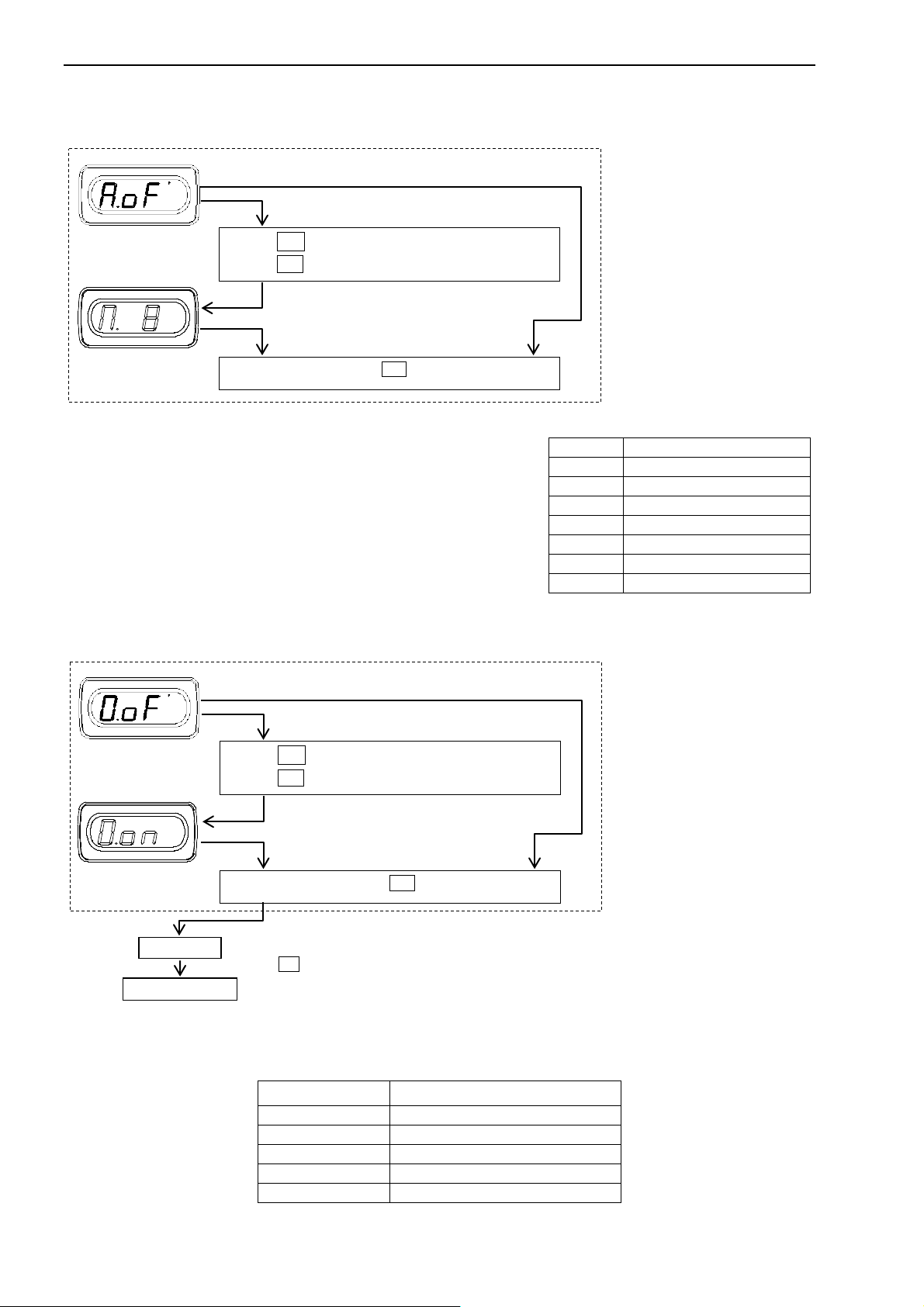
3.1.4 Ave rage oper ation
Aver age op erates the interval average or t he moving a vera ge.
Example: Changes the non-average operat ion to t he moving ave rage of 8-data.
Push the > switch to move to the setting mode. (blinking )
Push the Λ switch to set the contents of average operation.
- Since the in terval averag e o perates 6 -data, display cycle is approx. 400ms.
- In case of moving aver age, display cycle is appr ox. 67ms.
3.1.5 Zero set
Reset th e input sig n al electrically to zero.
Example: Change the zero set function from disable to ena ble.
Push the > switch to move to the setting mode. (blinking )
Push the Λ switch to set “on” or “off”.
[ Default ]
Function Setting value
Model 4022
- If you enable the zero set and
caus e short circuit bet w een the
zero set terminal and the COM
terminal, display shows the
offset value (as same as the
setting value at chapter 3.1.1)
Example:
If you execute the zero set at
100 when scaling 0-500,
display would show -100 to
0 to + 400.
:Enable the ze ro set.
:Disable the zero set.
Page 16
- 7 -
Display shows the input value. (DP1 and DP2 lit up)
Exit this paramet er by pressing M switch.
Measuring mode
Push F switch. Blinking for 1s ec onds.
Displaye d stra ight line lists.
Display
Input
Measuring mode
Display shows offset value. (DP0 and DP 1 lit up)
Setting mode
It change MAX adjustment by pressing M switch.
Push F switch for 6seconds.
Push M switch.
Displayed straight line translates.
Display
Input
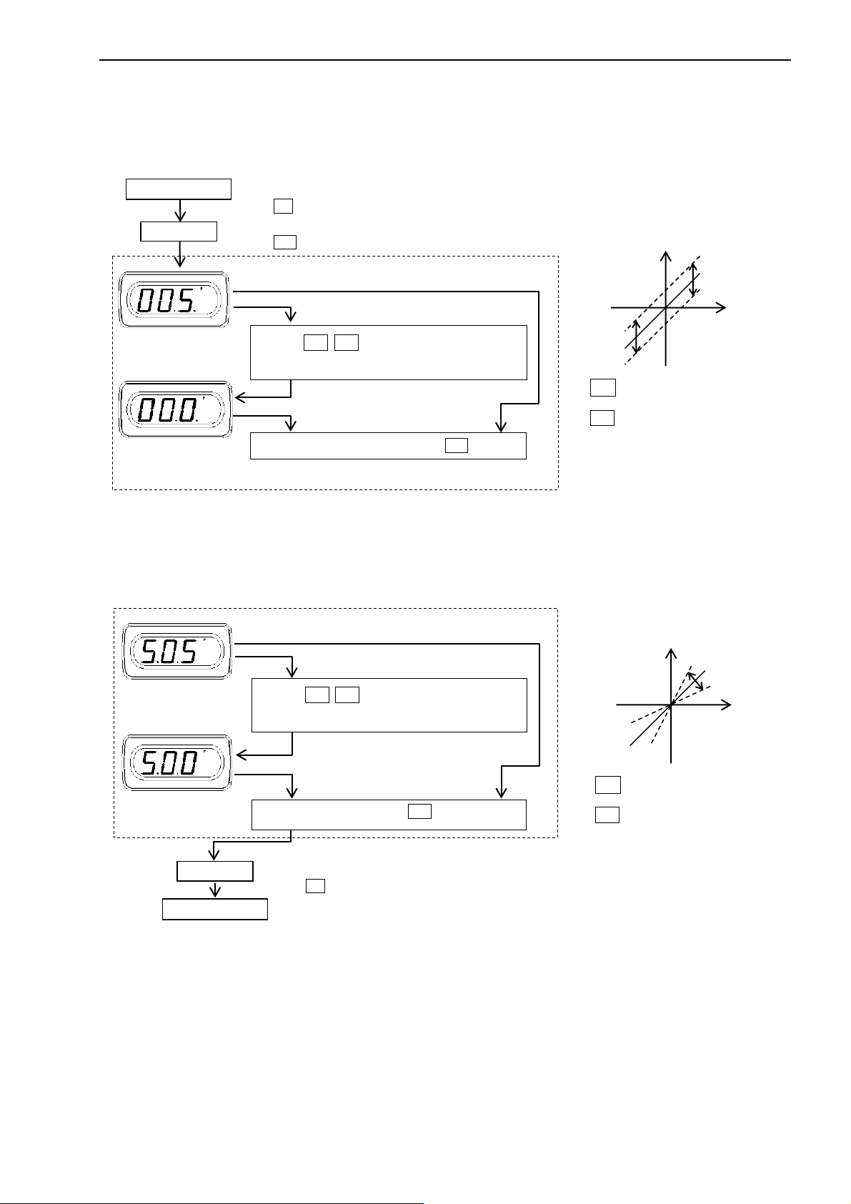
3.2 Adjustment function
3.2.1 Ze ro adjustment
Fine calibration of the offset display is available to meet the real input value.
Example: your me ter i s 1-5V input, and when inputting 1V, displayed value is 5, not 0.
3.2.2 MAX adjustment
Fine calibration of the maximum display is available to meet the real input value.
Supply the input as close as the rated maximum value.
Push the > Λ switch to adj usted to the offset
value.
Push the > Λ switch to adjusted to the full
scal e value.
Model 4022
> switch to scroll the setti ng va lue
to decrement.
Λ switch to scroll the setti ng value
to increments.
It may take a while if the scalin g wid th
is narrow. Keep th e s wi t c h e s pushin g
> switch to scroll the setting value
to decrement.
Λ switch to scroll the setti ng value
to increments.
It may take a while if the scalin g wid th
is narrow. Keep th e s wi t c h e s pushin g
Page 17
- 8 -
CAUTION
INHi
NC
INLo
DP1
DP2
COM
HOLD
PH
ZS
P2(+)
P1(-)
1 2 3 4 5 6 7 8 9
10
11
101digit
102digit
φ
3.
2
mi
n.
6max.
5.
3m
i
n.
4
.4
m
ax
.
DP1DP2COM
4. Wiring
● Do not mi swiring. Otherwise, the meter is broken.
● To avoid an electrical shock, turn the power off when wiring.
● Do not wire with moisten ed hand s . Locate aw ay from t he wet place.
● Do not touch terminals when turning the power on.
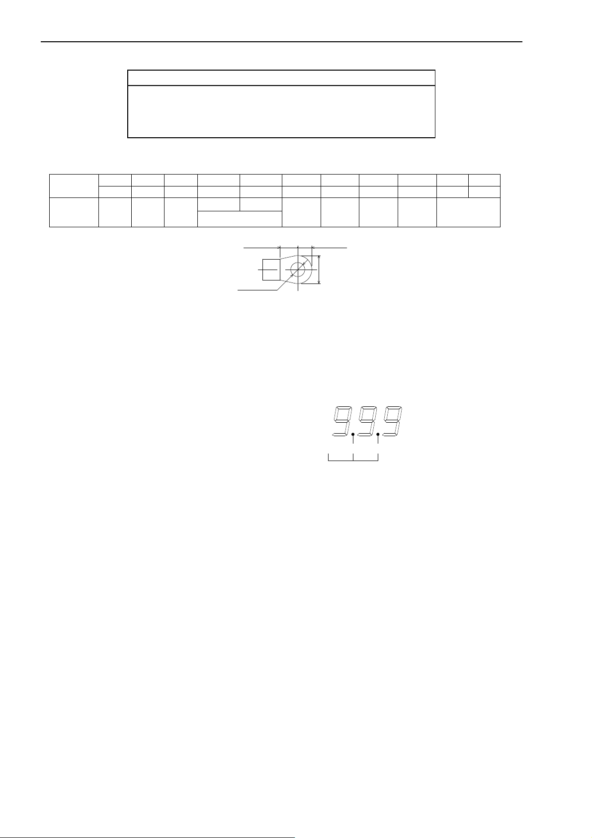
4.1 Terminal Arrangement
Terminal
Model 4022
Function Input
- Input
Deci m al point
Common Hold
Peak
hold
Zero
set
Power sup ply
Terminal screws: M3
Fas t ening torque: 0.46~0.62N・m
Crimp terminal: As shown on the right.
● Input terminals (I NHi, INL o)
Pay attention to the polarity when wiring. Connect input of higher electric potential to Hi. Input and power line shall lay separately.
Otherwis e, display may be u ns ta b le.
● Hold (HOLD)
Display can be held by connecting the Hold terminal and the Common terminal.
Active “L” I
● Decima l poin t (DP 1 , DP2)
Deci m al point i s programmable.
Connect and short-circuit the desired decimal point terminal,
DP1 or DP2, and the common terminal.
Active “L”, I
If you dup licat e both DP1 and D P2, de c imal point does n ot li ght up.
● Peak Hold (PH)
Maximum value is displayed by connecting the PH termi nal and the Com m on terminal. “ PH” LED are lit during th e peak h old
function. This function is released by disconnecting the PH terminal.
Active “L” I
● Bottom Hold (PH)
If your met er code is –A01, PH terminal is for the bottom hold. Minimum value is displayed by connecting the PH terminal and the
Common terminal. “PH” and LED are l it dur ing the bot tom hold function. This function is released by disconnecting the PH
terminal.
Active “L” I
● Zero set (ZS)
Zero set enables by choosing “on” at the rear switch. Zero set value is mem orized into EEPROM for approx. 1 0 years.
Active “L” I
- Method:
1. Shift the re ar swi tch of th e zero set to on side.
2. Input the zero set value, a nd cause short cir cu i t bet we en the zero set terminal and the COM terminal. Display s hows 0 (when you
set t he offs et va lue t o 0).
3. If you disconnect the zero set terminal and the COM termin al, zero set value is me m orized an d zero set function starts.
Display value = Input value – Zero set value.
- Release
1. Shift the rear switc h o f the zero set to off side. B ut zero set value is still memorized.
IL≦-1mA, “L”=0 to 0.8V, “H”=3. 5 to 5V
IL ≦-1mA, “L”= 0 to 0.8V, “ H ”=3.5 to 5V
IL≦-1mA, “L”=0 to 0.8V, “H”=3.5 to 5V
IL≦-1mA, “L”=0 to 0.8V, “H”=3.5 to 5V
IL≦-1mA, “L”=0 to 0.8V, “H”=3.5 to 5V
Page 18
Model 4022
- 9 -
CAUTION
● C om mon (CO M)
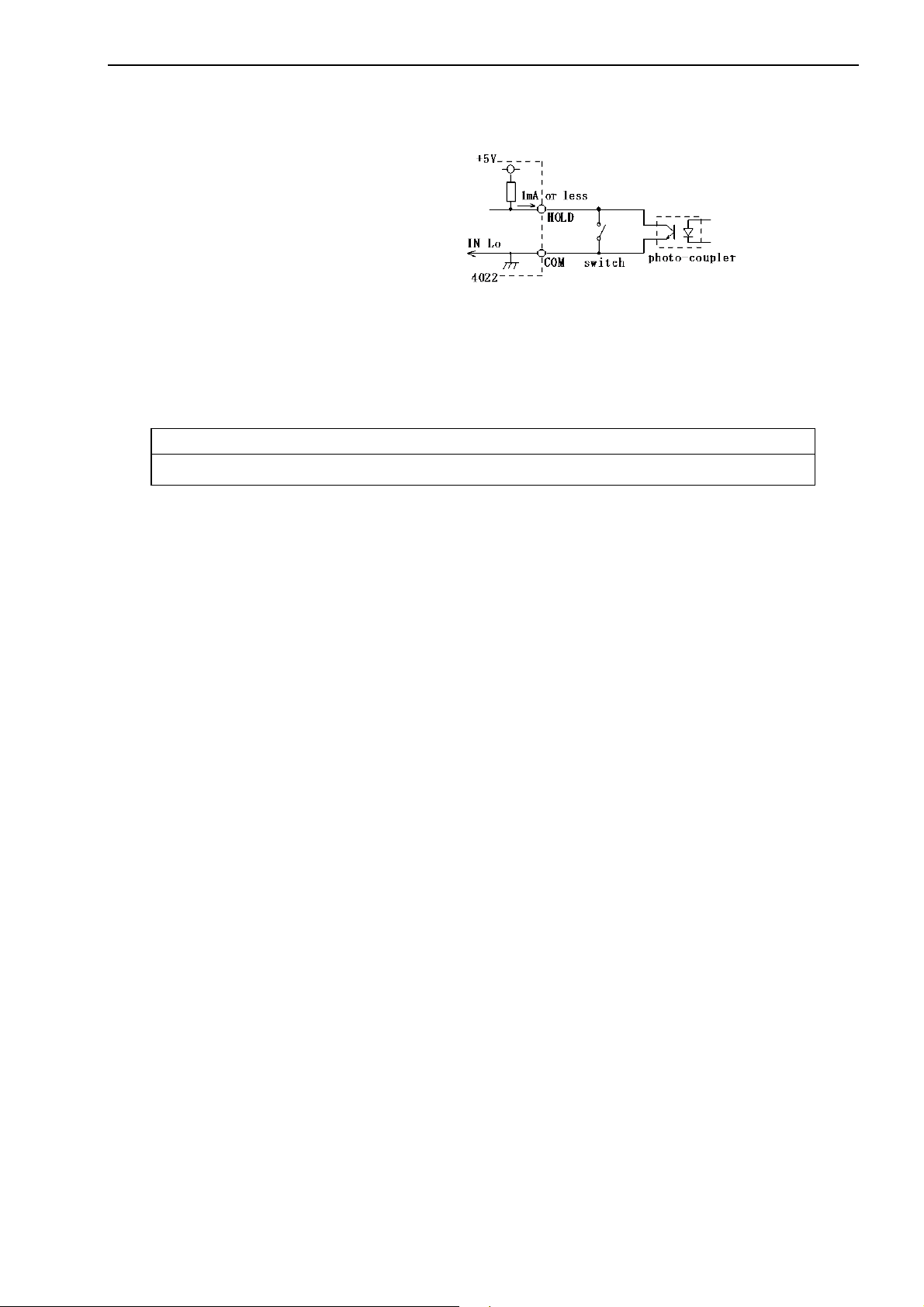
“COM” termina l i s used for H old and Peak ( or B ottom ) Hol d, Zero set, and Decima l poin t terminals.
NOTE: Those termin als, CO M , DP1, D P2, HOLD, ZS, PH, ar e not isolat ed to the inp ut.
Use a photo-coupler or switch to insulate.
It is essential when using the input floating.
● Power Supply (P1(-), P2(+ ))
The power supply voltage is specified on the terminal plate at delivery from our factory.
- AC po wer s upply(3): Use the meter within the range AC85 to 132V.
- AC power supply(5): Use the meter within the range AC170 to 250V.
- DC power supply(9): Use the met er within the range D C2 0 to 30V.
Connect +24V positive of DC pow er to P2 ( +), and 0V negative side to P1 (
-).
● D o not use the product with the voltage out of the rated range as it may cause breakage of the products.
5. Maintenance
Store the meter within the rated storage temperature (from -20 to + 70oC). When the front pan el or the case is cle aned, use sof t cloth
dipped with cl eane r l iquid. Do n ot use organ ic solvent like benze ne or pain t t hinn er as th ey may deform or discolor the case.
6. Calibration
In order to mai ntain long term ac cura cy, periodical calibration a t an interval of about one yea r is r ecommende d.
Refer to the chapter 3.2 for calibration.
Make a calibration in the ambi ent cond ition of 23
o
C±5oC, 75%RH or less.
Page 19
Model 4022
- 10 -
P
2-φ4.5
℃
P
2-φ4.5
P
R2.25
R4
4-φ4.5
R2.25
R4
Provided at both side
and bottom
Provided at both side
and bottom
3
52 10max
135
270
40
245
33.5
18
245
52
55
135
270
33.5
18
4
-
R
5
25
52
245
70
55
135
270
8
812
11
8
8
175
8
55
Split-able
Split-able
ton
V
Contact Information
Name : Tsuruga Electric Corporation
558-0041 Japan
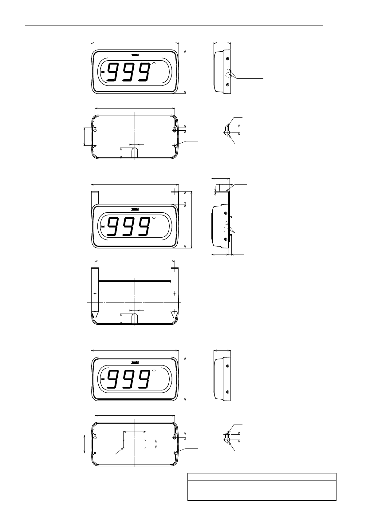
7. Dimensions
● Wall-mount (-51)
● Hanging-mount (-52)
● Sticking-mount (-53)
Unit: mm
Address : 1-3-23 Minami-Sumiyoshi, Sumiyoshi-ku, Osaka-shi
 Loading...