

Tsunami Multipoint MP-8200-BSU, 8000, Multipoint MP-8100-BSU, Multipoint MP-820-BSU-100, Multipoint MP-8100-SUA Antenna Installation Manual
...
Tsunami® 800 and 8000 Series
(Point-to-point and Point-to-multipoint Products)
Antenna Installation Guide
Products Covered
--> Tsunami® Multipoint
- MP-820-BSU-100
- MP-820-SUA-50
+
- MP-8100-BSU and MP-8200-BSU
- MP-8100-SUA
- MP-8200-SUA
- MP-8160-BSU
- MP-8160-SUA
--> Tsunami Quickbridge
®
- QB-8100-EPA
- QB-8100-LNK
- QB-8200-EPA
- QB-8200-LNK

Copyright
© 2013 Proxim Wireless Corporation, Milpitas, CA. All rights reserved. Covered by one or more of the following U.S. patents: 5,231,634;
5,875,179; 6,006,090; 5,809,060; 6,075,812; 5,077,753. The content described herein are copyrighted with all rights reserved. No part of this
publication may be reproduced, transmitted, transcribed, stored in a retrieval system, or translated into any language in any form by any means
without the written permission of Proxim Wireless Corporation.
Trademarks
Tsunami®, Proxim, and Proxim logo are the trademarks of Proxim Wireless Corporation. All other trademarks mentioned herein are the property of
their respective owners.
Disclaimer
Proxim reserves the right to revise this publication and to make changes in content from time-to-time without obligation on the part of Proxim to
provide notification of such revision or change. Proxim may make improvements or changes in the product(s) described in this guide at any time.
When using these device, basic safety precautions should always be followed to reduce the risk of fire, electric shock and injury to persons.
Tsunami® 800 and 8000 Series - Antenna Installation Guide
Documentation Version: 1.8
P/N 77036, February 2014
Tsunami® 800 and 8000 Series - Hardware Installation Guide 2

Preface. . . . . . . . . . . . . . . . . . . . . . . . . . . . . . . . . . . . . . . . . . . . . . . . . . . . . . . . . . . . . . . . . . . . . . 4
1 Antenna Installation . . . . . . . . . . . . . . . . . . . . . . . . . . . . . . . . . . . . . . . . . . . . . . . . . . . . . . . . . . . 7
Safety Precautions . . . . . . . . . . . . . . . . . . . . . . . . . . . . . . . . . . . . . . . . . . . . . . . . . . . . . . . . . . . . . . . . . . . . 7
Installation Process . . . . . . . . . . . . . . . . . . . . . . . . . . . . . . . . . . . . . . . . . . . . . . . . . . . . . . . . . . . . . . . . . . . 8
Required Materials . . . . . . . . . . . . . . . . . . . . . . . . . . . . . . . . . . . . . . . . . . . . . . . . . . . . . . . . . . . . . . . . . . . . . . . . . . 9
Determining the Optimal Antenna Placement . . . . . . . . . . . . . . . . . . . . . . . . . . . . . . . . . . . . . . . . . . . . . . . . . . . . . 9
Mounting the Antenna . . . . . . . . . . . . . . . . . . . . . . . . . . . . . . . . . . . . . . . . . . . . . . . . . . . . . . . . . . . . . . . . . . . . . . 10
Antenna Mast Requirements. . . . . . . . . . . . . . . . . . . . . . . . . . . . . . . . . . . . . . . . . . . . . . . . . . . . . . . . . . . . . . . .11
Connecting the Cables. . . . . . . . . . . . . . . . . . . . . . . . . . . . . . . . . . . . . . . . . . . . . . . . . . . . . . . . . . . . . . . . . . . . . . .11
Connecting the Antenna Cable . . . . . . . . . . . . . . . . . . . . . . . . . . . . . . . . . . . . . . . . . . . . . . . . . . . . . . . . . . . . . 12
Connecting the Surge Arrestor and Ethernet / Power cables . . . . . . . . . . . . . . . . . . . . . . . . . . . . . . . . . . . . . . 13
Grounding the System . . . . . . . . . . . . . . . . . . . . . . . . . . . . . . . . . . . . . . . . . . . . . . . . . . . . . . . . . . . . . . . . . . . 14
Sealing the Cable Connectors . . . . . . . . . . . . . . . . . . . . . . . . . . . . . . . . . . . . . . . . . . . . . . . . . . . . . . . . . . . . . . . . 14
Antenna Polarization . . . . . . . . . . . . . . . . . . . . . . . . . . . . . . . . . . . . . . . . . . . . . . . . . . . . . . . . . . . . . . . . . . . . . . . 18
Aligning the Antenna . . . . . . . . . . . . . . . . . . . . . . . . . . . . . . . . . . . . . . . . . . . . . . . . . . . . . . . . . . . . . . . . . . . . . . . 19
Audible Antenna Alignment. . . . . . . . . . . . . . . . . . . . . . . . . . . . . . . . . . . . . . . . . . . . . . . . . . . . . . . . . . . . . . . . 19
Antenna Alignment using CLI Commands . . . . . . . . . . . . . . . . . . . . . . . . . . . . . . . . . . . . . . . . . . . . . . . . . . . . 20
2 Measuring Signal Performance. . . . . . . . . . . . . . . . . . . . . . . . . . . . . . . . . . . . . . . . . . . . . . . . . 21
Introduction . . . . . . . . . . . . . . . . . . . . . . . . . . . . . . . . . . . . . . . . . . . . . . . . . . . . . . . . . . . . . . . . . . . . . . . . 21
Determining the Range . . . . . . . . . . . . . . . . . . . . . . . . . . . . . . . . . . . . . . . . . . . . . . . . . . . . . . . . . . . . . . . 21
Fresnel Zone . . . . . . . . . . . . . . . . . . . . . . . . . . . . . . . . . . . . . . . . . . . . . . . . . . . . . . . . . . . . . . . . . . . . . . . 22
Fresnel Zone Calculation . . . . . . . . . . . . . . . . . . . . . . . . . . . . . . . . . . . . . . . . . . . . . . . . . . . . . . . . . . . . . . . . . . . . 22
Clearance Factor . . . . . . . . . . . . . . . . . . . . . . . . . . . . . . . . . . . . . . . . . . . . . . . . . . . . . . . . . . . . . . . . . . . . 23
Calculations . . . . . . . . . . . . . . . . . . . . . . . . . . . . . . . . . . . . . . . . . . . . . . . . . . . . . . . . . . . . . . . . . . . . . . . . 25
Calculating Link Budget . . . . . . . . . . . . . . . . . . . . . . . . . . . . . . . . . . . . . . . . . . . . . . . . . . . . . . . . . . . . . . . . . . . . . 25
3 Statement of Warranty . . . . . . . . . . . . . . . . . . . . . . . . . . . . . . . . . . . . . . . . . . . . . . . . . . . . . . . . 29
4 Technical Services and Support . . . . . . . . . . . . . . . . . . . . . . . . . . . . . . . . . . . . . . . . . . . . . . . . 31
Tsunami® 800 and 8000 Series - Antenna Installation Guide 3
Preface
Preface
This chapter contains information on the following:
• About this Guide
• Who Should Use This Guide
• Documentation Conventions
• Related Documents
About this Guide
The guide gives an insight on how to set up and install the outdoor antenna(s) for the Tsunami® 800 and 8000 series
products that are tabulated below:
Product(s) Description
MP-820-BSU-100 The MP-820 Base Station unit, is a flexible wireless outdoor product that operates
in 5.150 – 5.925 GHz frequency band. This connectorized device comes with 2x2
MIMO radio and two N-Type connectors to connect external antennas. It provides
an aggregate throughput of 100 Mbps.
MP-820-SUA-50
+
The MP-820 Subscriber unit, is a flexible wireless outdoor product that operates
in 5.150 to 5.925 GHz frequency band. This connectorized device comes with a
2x2 MIMO radio and two N-Type connectors to connect external antennas. It
provides an aggregate throughput of 50 Mbps, license upgradable to 100 Mbps.
MP-8100-BSU The Tsunami MP-8100 Base Station unit, is a flexible wireless outdoor product
that operates in 2.3 – 2.5 and 4.9 – 6.0 GHz frequency band. This connectorized
device comes with a 3x3 MIMO radio and three N-Type connectors to connect
external antennas.
MP-8100-SUA The Tsunami MP-8100 Subscriber unit, is a flexible wireless outdoor product that
operates in 2.3 – 2.5 and 4.9 – 6.0 GHz frequency band. This connectorized
device comes with a 3x3 MIMO radio and three N-Type connectors to connect
external antennas.
MP-8200-BSU The Tsunami MP-8200 Base Station unit, is a flexible wireless outdoor product
that operates in 4.900 to 5.925 GHz frequency band. This connectorized device
comes with a 3x3 MIMO high power radio and three N-Type connectors to
connect external antennas.
MP-8200-SUA The Tsunami MP-8200 Subscriber unit, is a flexible wireless outdoor product
that operates in 4.900 to 5.925 GHz frequency band. This connectorized device
comes with a 3x3 MIMO high power radio and three N-Type connectors to
connect external antennas.
MP-8160-BSU The Tsunami MP-8160 Base Station unit, is a flexible outdoor product that
operates in 5.9 – 6.4 GHz frequency band. This connectorized device comes with
a high power 2x2 MIMO radio and two N-Type connectors to connect external
antennas.
Tsunami® 800 and 8000 Series - Antenna Installation Guide 4

Preface
MP-8160-SUA The Tsunami MP-8160 Subscriber unit, is a flexible outdoor product that operates
in 5.9 – 6.4 GHz frequency band. This connectorized device comes with a high
power 2x2 MIMO radio and two N-Type connectors to connect external
antennas.
QB-8100-EPA The Tsunami QB-8100-EPA QuickBridge operates in 2.3 – 2.5 and 4.9 – 6.0 GHz
frequency band. This connectorized device comes with a 3x3 MIMO radio and
three N-Type connectors to connect external antennas.
QB-8100-LNK A pair of Tsunami QB-8100-EPA devices form a link.
QB-8200-EPA The Tsunami QB-8200-EPA QuickBridge operates in 4.900 – 5.925 GHz
frequency band. This connectorized device comes with a 3x3 MIMO high power
radio and three N-Type connectors to connect external antennas.
QB-8200-LNK A pair of Tsunami QB-8200-EPA devices form a link.
Who Should Use This Guide
At a basic level, the person referring to this guide should meet the following pre-requisites:
• A professional experienced in mounting outdoor antennas, installing surge arrestors, installing and configuring
network components.
• Have a working knowledge on installation procedures for network operating systems like Microsoft Windows.
However, Proxim recommends only a qualified antenna installation professional to install the antennas and follow the
following guidelines:
• The outdoor antennas should be mounted only on an antenna tower, on a roof, or on the external surface of the
building.
• The site pre-requisites must be verified by the professional, familiar with the applicable national electrical code and
with other regulations governing this type of installation, within the country of use.
• If you are not aware about the regulations that apply in your country, contact Proxim’s Technical Services and
Support.
• While installing the outdoor antennas, ensure to comply with the local radio regulations and use the correct cable type
and surge arrestor.
• Local radio regulations or legislation may impose restrictions on the use of specific combinations of:
— Low - loss antenna cables and outdoor antennas.
— Selected radio channels that are connected to specific outdoor antennas.
Tsunami® 800 and 8000 Series - Antenna Installation Guide 5
Preface
Documentation Conventions
Icon Representation
Name Image Meaning
Note A special instruction that draws attention of a user.
Important A note of significant importance that a user should be aware of.
Caution A warning that cautions a user of the possible danger.
Related Documents
In addition to this guide, you can refer to the following documents for Tsunami® 800 and 8000 series products, that are
available at Proxim’s support site http://my.proxim.com.
• Quick Installation Guide (QIG) - A quick reference guide that provides essential information to install and configure
the device.
• Hardware Installation Guide - A guide that provides an overview about the installation methods and hardware
specifications of the device.
• Software Management Guide - A guide that gives jump-start working knowledge on the step-by-step procedure to
configure, manage and monitor the device, by using Web Interface.
• Reference Guide - A guide that provides instructions on how to configure, manage and monitor the device by using
Command Line Interface.
• Safety and Regulatory Compliance Guide - A guide that provides country specific safety and regulatory norms to
be followed while installing the devices.
• Recommended Antennas Guide - A guide that gives insight on the recommended antennas for the device, along
with the antenna specifications.
Tsunami® 800 and 8000 Series - Antenna Installation Guide 6

Antenna Installation
This chapter contains information on the following:
• Safety Precautions
• Installation Process
• Required Materials
• Determining the Optimal Antenna Placement
• Mounting the Antenna
— Antenna Mast Requirements
• Connecting the Cables
— Connecting the Antenna Cable
- Antenna Cable Routing
— Connecting the Surge Arrestor and Ethernet / Power cables
— Grounding the System
- Grounding the Antennas
• Sealing the Cable Connectors
• Antenna Polarization
• Aligning the Antenna
— Audible Antenna Alignment
— Antenna Alignment using CLI Commands
1
1.1 Safety Precautions
Listed below are the safety precautions to be satisfied, prior to the outdoor antennas installation:
• Outdoor antennas and antenna cables (good conductors of electricity) should be installed properly to avoid the
transients or electrostatic discharges (that occur due to lightning during thunderstorm) from damaging your
equipment and causing personal injury or death to the persons touching the exposed metal connectors of the
equipment.
• When installing, disconnecting, or replacing one of the cable components, ensure that each of the exposed metal
connectors of the antenna cabling system are grounded locally.
• Do not install the antenna, where there is a possibility of contact with the high-voltage arc-over from the power
cables or service drops to the buildings. Ensure that the antenna-mast or antenna-tower are not close by any power
line, during the installation or removal of antennas.
• Apply a Danger label on a plainly visible area of the antenna support structure.
• Do not climb the rooftops during a thunderstorm, in wet or windy conditions, or on the equipment installation area
which is covered with ice or snow.
• Do not touch the antennas, surge arrestors, or antenna cables during a thunderstorm.
• Install the antennas at a safe distance (at least twice the height of the antenna-mast plus the antenna) from power
lines or telephone lines.
• Mount the antennas at a safe distance, avoiding any human contact during the normal equipment operation.
• Ensure that the human proximity to the antenna is atleast 50 cm (8 inches) high, avoid the possibility of exceeding the
FCC radio frequency exposure limits, during the normal operation of the equipment.
Tsunami® 800 and 8000 Series - Antenna Installation Guide 7
Antenna Installation
• Verify that the low-loss antenna cable used to connect the antenna with the surge arrestor, or the ethernet cable used
to connect the surge arrestor, are at least 1 m (3 ft.) away from any high voltage current cable.
• Check whether the antenna mast and its guy wires or wall bracket are positioned correctly and secured properly to the
roof or walls. Also, ensure that the base area, where the antenna-mast is mounted is weatherproofed.
• Ensure, that the grounding system for the antenna mast and the surge arrestor have been installed. The grounding
system must comply with the local electrical code and other requirements. See Grounding the Antennas
• Always consult an experienced electrician to assure that the antenna mast, surge arrestor, and the equipment
hardware are grounded properly.
• The antenna cable between the antenna and the surge arrestor should be grounded. Ensure that the exposed metal
connector of the cable is grounded locally, if the cable is disconnected at one end (disconnected to replace the surge
arrestor).
1.2 Installation Process
Follow the following step-by-step procedure to install outdoor antennas:
1. Ensure that all the materials, essential to install the outdoor antennas are acquired. See Required Materials.
2. Once you have acquired all the required materials, refer Quick Installation Guide (that comes along with your product)
to mount the outdoor equipment and begin the outdoor antenna installation.
3. Verify the optimal antenna placement, maintaining a clear line-of-sight. See Determining the Optimal Antenna
Placement.
4. Mount the antenna to the support structure, following the guidelines as described in Mounting the Antenna.
5. Verify that the device, support structure for antenna (antenna-mast) and entire cable set-up for the antenna are
connected properly. See Connecting the Cables.
6. Connect the antenna cable to the antenna. See Connecting the Antenna Cable.
7. Ensure that the cabling of ethernet / power cables and the surge arrestor is proper. See Connecting the Surge
Arrestor and Ethernet / Power cables
8. Ensure that the antennas are grounded properly to the grounding system, satisfying the local electrical code
requirements. See Grounding the Antennas
9. Once the antenna is properly positioned, grounded and the outdoor cable setup is verified, secure all the cables and
use weatherproofing tape to seal all the outdoor connectors. See Sealing the Cable Connectors.
10. Make sure that the outdoor antennas at both the ends maintain the same antenna polarizations. See Step 4: Next,
wrap a layer of the butyl mastic tape on the adhesive side.
11. Align the antennas to establish a wireless link with a better throughput, by using device antenna alignment utilities
like Audible Antenna Alignment and Antenna Alignment using CLI commands. See Aligning the Antenna.
: For easy outdoor antenna installation, note the following:
• Go through the Safety Precautions.
• Read all the requirements outlined in this chapter. See Required Materials.
• Familiarize yourself with the antenna and the radio-specific mounting instructions, prior to climbing any roof or
ladder.
• Verify that you have arranged all safety measures for outdoor installation or rooftop installation. See Safety
Precautions.
• Test all the equipment before beginning the actual rooftop installation, to determine if all the required equipment is
functioning properly.
Tsunami® 800 and 8000 Series - Antenna Installation Guide 8
Antenna Installation
• Install the grounding system for the antenna mast, device, and surge arrestor before connecting the cables. This
protects your system against lightning strikes during installation.
• When you remove or relocate the antenna, verify the Required Materials and Safety Precautions, before you
restart the installation process, and follow the above steps in exactly the reverse order.
1.2.1 Required Materials
The outdoor installation of the equipment and the antennas, require the following:
• An outdoor radio unit.
• An outdoor antenna, supporting the local electrical code.
• A low-loss antenna cable.
: We recommend you to use a coaxial antenna cable (P/N CBL-5054-600-6), that is available with your
distributor.
• Antenna mast or wall bracket for the antenna/device.
• A grounding system that meets the local electrical code. See Grounding the System
• Weatherproofing kit for sealing all the cable connections. See Sealing the Cable Connectors
• Tools and material to mount the antenna. See Mounting the Antenna
• Tape or wraps to attach the antenna cable to the mast.
• Ethernet cable (RJ 45 cable / CAT5e or CAT6 cable) with waterproof cap.
• Proper tools for system installation.
• Ethernet Surge Arrestor and Surge Protector (RF-cable). See Connecting the Surge Arrestor and Ethernet / Power
cables
Ensure that you have acquired all the materials listed above, to begin with the outdoor antenna installation. Refer to the
Quick Installation Guide, that comes along with your product, for details on mounting the outdoor equipment.
1.2.2 Determining the Optimal Antenna Placement
To achieve the maximum throughput, the outdoor antenna must have clear line-of-sight with the antenna at the other end.
The outdoor antennas are said to have a clear line-of-sight, when there are:
• No obstacles in the direct path between the antennas (antenna beam)
• No obstacles within a defined zone around the antenna beam
Although, the radio signal can work well without the clear line-of-sight in urban environments, where the signal is
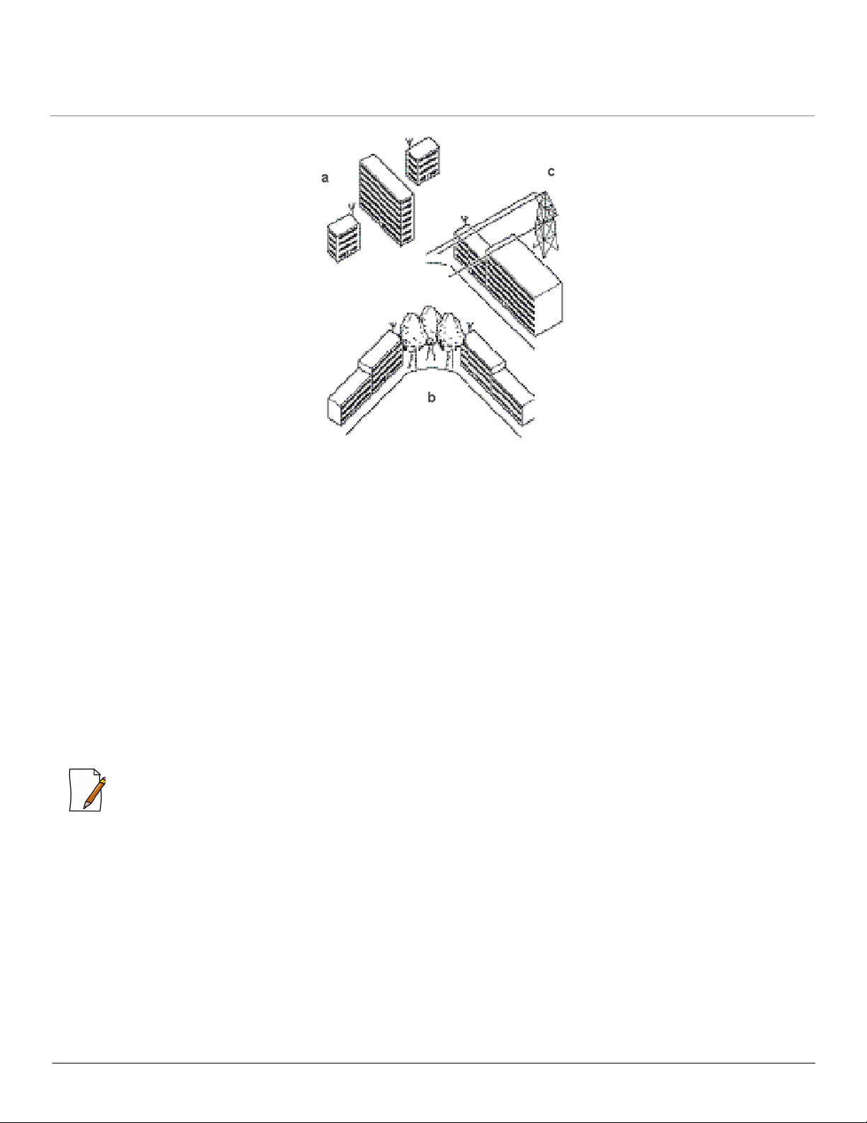
transported by reflection rather than transporting it directly along the obstacles. The following figure shows some typical
examples of obstacles you must avoid in urban environments, for the directional antenna to operate effectively.
Tsunami® 800 and 8000 Series - Antenna Installation Guide 9
Antenna Installation
Figure 1-1 Obstacles to be avoided : (a) Neighbouring Buildings (b) Tall Trees (c) Power Lines
To minimize the signal interference or reflections due to obstacles, note the following guidelines:
• Mount the antenna as high as possible above the ground to allow maximum clearance.
— In open areas, ‘ground’ is the actual surface of the earth.
— In dense urban areas, ‘ground’ is to be interpreted as the height of the highest obstacle in the signal path
between the two antenna sites.
• Avoid trees in the signal path to avoid signal absorption due to seasonal changes (leaves or ice).
• Install the antenna at least 2 m (6 ft.) away from all other antennas.
Other situations in which reflections of the radio signal may cause interference are environments with large reflecting
surfaces, parallel or partly perpendicular to the antenna beam, such as:
• Mirror-glass buildings.
• Crowded parking lots.
• Water surface, moist earth and moist vegetation.
• Electric power lines and telephone lines above the ground level.
: Reflective surfaces can be used to improve the performance of a link, if the direct line-of-sight is impaired or absent.
In the absence of a direct path or clear line-of-sight, transporting a signal through reflection depends on two factors:
• Fresnel Zone: It is required to calculate the distance of the obstacle from the antenna. See Fresnel Zone
• Clearance Factor: It is required for optimal performance (See Clearance Factor). Ensure that the type and placement
of the antennas leave sufficient clearance of the Fresnel Zone at the maximum width of the bulge, which is typically at
the mid-point between the antennas.
1.2.3 Mounting the Antenna
Mounting an antenna directly to the wall does not let you align the antenna properly with the corresponding antenna at the
opposite end of your wireless link. Poor antenna alignment typically results in poor performance and therefore, we
recommend mounting the antennas to a mast.
Tsunami® 800 and 8000 Series - Antenna Installation Guide 10
Antenna Installation
The two methods followed frequently to erect an antenna mast are:
• Tripod Mount: The tripod mount is used primarily on peak and flat roofs. The antenna mast must be secured to the
roof using three or four guy wires equally spaced around the mast. When the height of the antenna mast is more than
3 meters (10 ft.), you should use at least three guy wires for every 3-meter (10-foot) section of the mast.
• Wall (Side) Mount: A wall (side) mount allows you to mount the antenna (mast) on the side of a building or on the
side of an elevator penthouse. This provides you with a convenient mounting location, when the roof overhang is not
excessive or when the location is high enough to provide a clear line-of-sight.
When mounting multiple antennas on a single mast, use the following methods to minimize the influence of cross-talk
interference between the antennas:
– Place your antennas as far as possible.
– Mount the directional antennas, such that the identical side of both the antennas face the same direction.
– For 8xxx connectorized unit, use the antenna port A1, if you are using a single polarized antenna. Use the antenna
port A1 and A3, if If you are using a dual polarized antenna.
– For 82x connectorized unit, use antenna ports A1 and A2 for dual polarized antenna.
: As the mounting procedures for the various antennas differ from one another, refer to the guide that comes along
with the antenna.
: The antennas installed at both the ends of a wireless link should maintain same antenna
polarizations. See Step 4: Next, wrap a layer of the butyl mastic tape on the adhesive side.
1.2.3.1 Antenna
To accommodate the antennas, the antenna mast must satisfy the following requirements:
• The construction of the antenna mast must contain sturdy, weatherproof, and non-corrosive material (for example,
galvanized or stainless steel construction pipe).
• Diameter of the mast should be between 35 mm (1.4 inches) and 41 mm (1.6 inches). The diameter of the antenna mast
vary depending on the type of antenna you intend to install.
• The height of the antenna mast must be high enough to allow the antenna to be installed at least 1.5 m (5 ft.) above the
roof. The height of the antenna should be at least 3 m (10 ft.) above, if it is a metal roof.
• The antenna mast or wall bracket must be free from any material (like paint) that prevents a good electrical conduction
with the antenna.
Mast Requirements
1.2.4 Connecting the Cables
Once the outdoor antennas are properly mounted, the cable setup essential to complete the outdoor antenna installation is
depicted in the following figure:
Tsunami® 800 and 8000 Series - Antenna Installation Guide 11
 Loading...