

Tsunami 5054 (MP.11a), 5054, MP.11a, MP.11 Installation And Management Manual

Tsunami MP.11 Installation and Management
Model 5054 (MP.11a)
Version 4.0.0

MP.11 5054 (MP.11a) Installation and Management
2
Copyright
©2007 Proxim Wireless Corporation, San Jose, CA. All rights reserved. Covered by one or more of the following U.S. patents: 5,231,634;
5,875,179; 6,006,090; 5,809,060; 6,075,812; 5,077,753. This manual and the software described herein are copyrighted with all rights
reserved. No part of this publication may be reproduced, transmitted, transcribed, stored in a retrieval system, or translated into any language
in any form by any means without the written permission of Proxim Wireless Corporation.
Trademarks
Tsunami, Proxim, and the Proxim logo are trademarks of Proxim Wireless Corporation. All other trademarks mentioned herein are the property
of their respective owners.
Tsunami MP.11 5054 (MP.11a) Installation and Management Guide
P/N 73871 June 2007
IMPORTANT!
Before installing and using this product, see the
Safety and Regulatory Compliance Guide located on the product CD.

MP.11 5054 (MP.11a) Installation and Management
3
Contents
1 Introduction . . . . . . . . . . . . . . . . . . . . . . . . . . . . . . . . . . . . . . . . . . . . . . . . . . . . . . . . . . . . . . . . . . 9
About This Book . . . . . . . . . . . . . . . . . . . . . . . . . . . . . . . . . . . . . . . . . . . . . . . . . . . . . . . . . . . . . . . . . . . . . . 9
Reference Manual . . . . . . . . . . . . . . . . . . . . . . . . . . . . . . . . . . . . . . . . . . . . . . . . . . . . . . . . . . . . . . . . . . . 10
Wireless Network Topologies . . . . . . . . . . . . . . . . . . . . . . . . . . . . . . . . . . . . . . . . . . . . . . . . . . . . . . . . . . . 11
Point-to-Point Link . . . . . . . . . . . . . . . . . . . . . . . . . . . . . . . . . . . . . . . . . . . . . . . . . . . . . . . . . . . . . . . . . . . . . . . . . 11
Point-to-Multipoint Network . . . . . . . . . . . . . . . . . . . . . . . . . . . . . . . . . . . . . . . . . . . . . . . . . . . . . . . . . . . . . . . . . . 12
Management and Monitoring Capabilities . . . . . . . . . . . . . . . . . . . . . . . . . . . . . . . . . . . . . . . . . . . . . . . . . 12
Web Interface . . . . . . . . . . . . . . . . . . . . . . . . . . . . . . . . . . . . . . . . . . . . . . . . . . . . . . . . . . . . . . . . . . . . . . . . . . . . . 12
Command Line Interface . . . . . . . . . . . . . . . . . . . . . . . . . . . . . . . . . . . . . . . . . . . . . . . . . . . . . . . . . . . . . . . . . . . . 12
SNMP Management . . . . . . . . . . . . . . . . . . . . . . . . . . . . . . . . . . . . . . . . . . . . . . . . . . . . . . . . . . . . . . . . . . . . . . . . 12
2 Installation and Initialization . . . . . . . . . . . . . . . . . . . . . . . . . . . . . . . . . . . . . . . . . . . . . . . . . . . 14
Hardware Overview . . . . . . . . . . . . . . . . . . . . . . . . . . . . . . . . . . . . . . . . . . . . . . . . . . . . . . . . . . . . . . . . . . 15
Power-over-Ethernet . . . . . . . . . . . . . . . . . . . . . . . . . . . . . . . . . . . . . . . . . . . . . . . . . . . . . . . . . . . . . . . . . . . . . . . 15
Product Package . . . . . . . . . . . . . . . . . . . . . . . . . . . . . . . . . . . . . . . . . . . . . . . . . . . . . . . . . . . . . . . . . . . . 16
Installation Procedure . . . . . . . . . . . . . . . . . . . . . . . . . . . . . . . . . . . . . . . . . . . . . . . . . . . . . . . . . . . . . . . . . 18
Step 1: Choose a Location . . . . . . . . . . . . . . . . . . . . . . . . . . . . . . . . . . . . . . . . . . . . . . . . . . . . . . . . . . . . . . . . . . . 20
Step 2: Unpack Shipping Box. . . . . . . . . . . . . . . . . . . . . . . . . . . . . . . . . . . . . . . . . . . . . . . . . . . . . . . . . . . . . . . . . 20
Step 3: Attach Base (for Desktop or Ceiling Mounting only). . . . . . . . . . . . . . . . . . . . . . . . . . . . . . . . . . . . . . . . . . 21
Step 4: Remove Covers . . . . . . . . . . . . . . . . . . . . . . . . . . . . . . . . . . . . . . . . . . . . . . . . . . . . . . . . . . . . . . . . . . . . . 22
Step 5: Connect the Cables . . . . . . . . . . . . . . . . . . . . . . . . . . . . . . . . . . . . . . . . . . . . . . . . . . . . . . . . . . . . . . . . . . 23
Step 6: Mount the Unit . . . . . . . . . . . . . . . . . . . . . . . . . . . . . . . . . . . . . . . . . . . . . . . . . . . . . . . . . . . . . . . . . . . . . . 24
Step 7: Power on the Unit. . . . . . . . . . . . . . . . . . . . . . . . . . . . . . . . . . . . . . . . . . . . . . . . . . . . . . . . . . . . . . . . . . . . 28
Step 8: View LEDs . . . . . . . . . . . . . . . . . . . . . . . . . . . . . . . . . . . . . . . . . . . . . . . . . . . . . . . . . . . . . . . . . . . . . . . . . 28
Step 9: Align the Antenna. . . . . . . . . . . . . . . . . . . . . . . . . . . . . . . . . . . . . . . . . . . . . . . . . . . . . . . . . . . . . . . . . . . . 29
Step 10: Attach Kensington Security Lock (Optional) . . . . . . . . . . . . . . . . . . . . . . . . . . . . . . . . . . . . . . . . . . . . . . . 30
Step 11: Install Documentation and Software . . . . . . . . . . . . . . . . . . . . . . . . . . . . . . . . . . . . . . . . . . . . . . . . . . . . . 31
Initialization . . . . . . . . . . . . . . . . . . . . . . . . . . . . . . . . . . . . . . . . . . . . . . . . . . . . . . . . . . . . . . . . . . . . . . . . . 32
ScanTool. . . . . . . . . . . . . . . . . . . . . . . . . . . . . . . . . . . . . . . . . . . . . . . . . . . . . . . . . . . . . . . . . . . . . . . . . . . . . . . . . 32
Setting the IP Address with ScanTool. . . . . . . . . . . . . . . . . . . . . . . . . . . . . . . . . . . . . . . . . . . . . . . . . . . . . . . . . . . 32
Logging in to the Web Interface . . . . . . . . . . . . . . . . . . . . . . . . . . . . . . . . . . . . . . . . . . . . . . . . . . . . . . . . . 34
3 System Overview . . . . . . . . . . . . . . . . . . . . . . . . . . . . . . . . . . . . . . . . . . . . . . . . . . . . . . . . . . . . 35
Changing Basic Configuration Information . . . . . . . . . . . . . . . . . . . . . . . . . . . . . . . . . . . . . . . . . . . . . . . . . 35
Country and Related Settings. . . . . . . . . . . . . . . . . . . . . . . . . . . . . . . . . . . . . . . . . . . . . . . . . . . . . . . . . . . . . . . . . 35
Dynamic Frequency Selection (DFS) . . . . . . . . . . . . . . . . . . . . . . . . . . . . . . . . . . . . . . . . . . . . . . . . . . . . . . . . . . . 36
Transmit Power Control . . . . . . . . . . . . . . . . . . . . . . . . . . . . . . . . . . . . . . . . . . . . . . . . . . . . . . . . . . . . . . . . . . . . . 37
SU Registration . . . . . . . . . . . . . . . . . . . . . . . . . . . . . . . . . . . . . . . . . . . . . . . . . . . . . . . . . . . . . . . . . . . . . 38
Dynamic Data Rate Selection (DDRS) . . . . . . . . . . . . . . . . . . . . . . . . . . . . . . . . . . . . . . . . . . . . . . . . . . . . 39
Virtual Local Area Networks (VLANs) . . . . . . . . . . . . . . . . . . . . . . . . . . . . . . . . . . . . . . . . . . . . . . . . . . . . . 40

MP.11 5054 (MP.11a) Installation and Management
4
Quality of Service (QoS) . . . . . . . . . . . . . . . . . . . . . . . . . . . . . . . . . . . . . . . . . . . . . . . . . . . . . . . . . . . . . . 41
Concepts and Definitions . . . . . . . . . . . . . . . . . . . . . . . . . . . . . . . . . . . . . . . . . . . . . . . . . . . . . . . . . . . . . . . . . . . . 41
4 Basic Management . . . . . . . . . . . . . . . . . . . . . . . . . . . . . . . . . . . . . . . . . . . . . . . . . . . . . . . . . . . 45
Navigation . . . . . . . . . . . . . . . . . . . . . . . . . . . . . . . . . . . . . . . . . . . . . . . . . . . . . . . . . . . . . . . . . . . . . . . . . 45
Rebooting and Resetting . . . . . . . . . . . . . . . . . . . . . . . . . . . . . . . . . . . . . . . . . . . . . . . . . . . . . . . . . . . . . . 46
Rebooting. . . . . . . . . . . . . . . . . . . . . . . . . . . . . . . . . . . . . . . . . . . . . . . . . . . . . . . . . . . . . . . . . . . . . . . . . . . . . . . . 46
Resetting Hardware . . . . . . . . . . . . . . . . . . . . . . . . . . . . . . . . . . . . . . . . . . . . . . . . . . . . . . . . . . . . . . . . . . . . . . . . 46
Soft Reset to Factory Default . . . . . . . . . . . . . . . . . . . . . . . . . . . . . . . . . . . . . . . . . . . . . . . . . . . . . . . . . . . . . . . . . 47
General Configuration Settings . . . . . . . . . . . . . . . . . . . . . . . . . . . . . . . . . . . . . . . . . . . . . . . . . . . . . . . . . 48
Monitoring Settings . . . . . . . . . . . . . . . . . . . . . . . . . . . . . . . . . . . . . . . . . . . . . . . . . . . . . . . . . . . . . . . . . . 49
Security Settings . . . . . . . . . . . . . . . . . . . . . . . . . . . . . . . . . . . . . . . . . . . . . . . . . . . . . . . . . . . . . . . . . . . . 50
Encryption . . . . . . . . . . . . . . . . . . . . . . . . . . . . . . . . . . . . . . . . . . . . . . . . . . . . . . . . . . . . . . . . . . . . . . . . . . . . . . . 50
Passwords . . . . . . . . . . . . . . . . . . . . . . . . . . . . . . . . . . . . . . . . . . . . . . . . . . . . . . . . . . . . . . . . . . . . . . . . . . . . . . . 50
Default Settings . . . . . . . . . . . . . . . . . . . . . . . . . . . . . . . . . . . . . . . . . . . . . . . . . . . . . . . . . . . . . . . . . . . . . 51
Upgrading the Unit . . . . . . . . . . . . . . . . . . . . . . . . . . . . . . . . . . . . . . . . . . . . . . . . . . . . . . . . . . . . . . . . . . . 53
5 System Status. . . . . . . . . . . . . . . . . . . . . . . . . . . . . . . . . . . . . . . . . . . . . . . . . . . . . . . . . . . . . . . 54
Status . . . . . . . . . . . . . . . . . . . . . . . . . . . . . . . . . . . . . . . . . . . . . . . . . . . . . . . . . . . . . . . . . . . . . . . . . . . . . 54
System Status . . . . . . . . . . . . . . . . . . . . . . . . . . . . . . . . . . . . . . . . . . . . . . . . . . . . . . . . . . . . . . . . . . . . . . . . . . . . 54
Systems Traps . . . . . . . . . . . . . . . . . . . . . . . . . . . . . . . . . . . . . . . . . . . . . . . . . . . . . . . . . . . . . . . . . . . . . . . . . . . . 54
Event Log . . . . . . . . . . . . . . . . . . . . . . . . . . . . . . . . . . . . . . . . . . . . . . . . . . . . . . . . . . . . . . . . . . . . . . . . . . 55
6 Configuration . . . . . . . . . . . . . . . . . . . . . . . . . . . . . . . . . . . . . . . . . . . . . . . . . . . . . . . . . . . . . . . 56
System Parameters . . . . . . . . . . . . . . . . . . . . . . . . . . . . . . . . . . . . . . . . . . . . . . . . . . . . . . . . . . . . . . . . . . 56
Bridge and Routing Modes. . . . . . . . . . . . . . . . . . . . . . . . . . . . . . . . . . . . . . . . . . . . . . . . . . . . . . . . . . . . . . . . . . . 58
Network Parameters . . . . . . . . . . . . . . . . . . . . . . . . . . . . . . . . . . . . . . . . . . . . . . . . . . . . . . . . . . . . . . . . . 61
IP Configuration . . . . . . . . . . . . . . . . . . . . . . . . . . . . . . . . . . . . . . . . . . . . . . . . . . . . . . . . . . . . . . . . . . . . . . . . . . . 61
Roaming. . . . . . . . . . . . . . . . . . . . . . . . . . . . . . . . . . . . . . . . . . . . . . . . . . . . . . . . . . . . . . . . . . . . . . . . . . . . . . . . . 62
DHCP Server . . . . . . . . . . . . . . . . . . . . . . . . . . . . . . . . . . . . . . . . . . . . . . . . . . . . . . . . . . . . . . . . . . . . . . . . . . . . . 65
Spanning Tree (Bridge Mode Only) . . . . . . . . . . . . . . . . . . . . . . . . . . . . . . . . . . . . . . . . . . . . . . . . . . . . . . . . . . . . 67
IP Routes (Routing Mode Only) . . . . . . . . . . . . . . . . . . . . . . . . . . . . . . . . . . . . . . . . . . . . . . . . . . . . . . . . . . . . . . . 68
DHCP Relay Agent (Routing Mode Only) . . . . . . . . . . . . . . . . . . . . . . . . . . . . . . . . . . . . . . . . . . . . . . . . . . . . . . . 69
Interface Parameters . . . . . . . . . . . . . . . . . . . . . . . . . . . . . . . . . . . . . . . . . . . . . . . . . . . . . . . . . . . . . . . . . 71
Wireless . . . . . . . . . . . . . . . . . . . . . . . . . . . . . . . . . . . . . . . . . . . . . . . . . . . . . . . . . . . . . . . . . . . . . . . . . . . . . . . . . 71
Ethernet . . . . . . . . . . . . . . . . . . . . . . . . . . . . . . . . . . . . . . . . . . . . . . . . . . . . . . . . . . . . . . . . . . . . . . . . . . . . . . . . . 82
SNMP Parameters . . . . . . . . . . . . . . . . . . . . . . . . . . . . . . . . . . . . . . . . . . . . . . . . . . . . . . . . . . . . . . . . . . . 83
Trap Host Table . . . . . . . . . . . . . . . . . . . . . . . . . . . . . . . . . . . . . . . . . . . . . . . . . . . . . . . . . . . . . . . . . . . . . . . . . . . 83
Management Parameters . . . . . . . . . . . . . . . . . . . . . . . . . . . . . . . . . . . . . . . . . . . . . . . . . . . . . . . . . . . . . . 85
Passwords . . . . . . . . . . . . . . . . . . . . . . . . . . . . . . . . . . . . . . . . . . . . . . . . . . . . . . . . . . . . . . . . . . . . . . . . . . . . . . . 85
Services . . . . . . . . . . . . . . . . . . . . . . . . . . . . . . . . . . . . . . . . . . . . . . . . . . . . . . . . . . . . . . . . . . . . . . . . . . . . . . . . . 85

MP.11 5054 (MP.11a) Installation and Management
5
Security Parameters . . . . . . . . . . . . . . . . . . . . . . . . . . . . . . . . . . . . . . . . . . . . . . . . . . . . . . . . . . . . . . . . . . 88
MAC Authentication (BSU Only) . . . . . . . . . . . . . . . . . . . . . . . . . . . . . . . . . . . . . . . . . . . . . . . . . . . . . . . . . . . . . . 88
Encryption . . . . . . . . . . . . . . . . . . . . . . . . . . . . . . . . . . . . . . . . . . . . . . . . . . . . . . . . . . . . . . . . . . . . . . . . . . . . . . . 89
RADIUS Authentication (BSU Only). . . . . . . . . . . . . . . . . . . . . . . . . . . . . . . . . . . . . . . . . . . . . . . . . . . . . . . . . . . . 89
Filtering Parameters . . . . . . . . . . . . . . . . . . . . . . . . . . . . . . . . . . . . . . . . . . . . . . . . . . . . . . . . . . . . . . . . . . 91
Overview . . . . . . . . . . . . . . . . . . . . . . . . . . . . . . . . . . . . . . . . . . . . . . . . . . . . . . . . . . . . . . . . . . . . . . . . . . . . . . . . 91
Ethernet Protocol . . . . . . . . . . . . . . . . . . . . . . . . . . . . . . . . . . . . . . . . . . . . . . . . . . . . . . . . . . . . . . . . . . . . . . . . . . 92
Static MAC Address Filtering . . . . . . . . . . . . . . . . . . . . . . . . . . . . . . . . . . . . . . . . . . . . . . . . . . . . . . . . . . . . . . . . . 93
Storm Threshold. . . . . . . . . . . . . . . . . . . . . . . . . . . . . . . . . . . . . . . . . . . . . . . . . . . . . . . . . . . . . . . . . . . . . . . . . . . 96
Broadcast Protocol Filtering . . . . . . . . . . . . . . . . . . . . . . . . . . . . . . . . . . . . . . . . . . . . . . . . . . . . . . . . . . . . . . . . . . 96
IP Access Table Filtering . . . . . . . . . . . . . . . . . . . . . . . . . . . . . . . . . . . . . . . . . . . . . . . . . . . . . . . . . . . . . . . . . . . . 97
Intra-Cell Blocking (BSU Only; Bridge Mode Only) . . . . . . . . . . . . . . . . . . . . . . . . . . . . . . . . . . . . . . . . . . 99
Overview . . . . . . . . . . . . . . . . . . . . . . . . . . . . . . . . . . . . . . . . . . . . . . . . . . . . . . . . . . . . . . . . . . . . . . . . . . . . . . . . 99
Intra-Cell Blocking Group Table . . . . . . . . . . . . . . . . . . . . . . . . . . . . . . . . . . . . . . . . . . . . . . . . . . . . . . . . . . . . . . . 99
MAC Table . . . . . . . . . . . . . . . . . . . . . . . . . . . . . . . . . . . . . . . . . . . . . . . . . . . . . . . . . . . . . . . . . . . . . . . . . . . . . . 101
Security Gateway . . . . . . . . . . . . . . . . . . . . . . . . . . . . . . . . . . . . . . . . . . . . . . . . . . . . . . . . . . . . . . . . . . . . . . . . . 102
VLAN Parameters (BSU Only; Bridge Mode Only) . . . . . . . . . . . . . . . . . . . . . . . . . . . . . . . . . . . . . . . . . 103
Overview . . . . . . . . . . . . . . . . . . . . . . . . . . . . . . . . . . . . . . . . . . . . . . . . . . . . . . . . . . . . . . . . . . . . . . . . . . . . . . . 103
BSU VLAN Configuration . . . . . . . . . . . . . . . . . . . . . . . . . . . . . . . . . . . . . . . . . . . . . . . . . . . . . . . . . . . . . . . . . . . 108
SU VLAN Configuration . . . . . . . . . . . . . . . . . . . . . . . . . . . . . . . . . . . . . . . . . . . . . . . . . . . . . . . . . . . . . . . . . . . . 109
QoS (Quality of Service) Parameters (BSU Only) . . . . . . . . . . . . . . . . . . . . . . . . . . . . . . . . . . . . . . . . . . 112
QoS PIR Configuration. . . . . . . . . . . . . . . . . . . . . . . . . . . . . . . . . . . . . . . . . . . . . . . . . . . . . . . . . . . . . . . . . . . . . .112
QoS SFC Configuration . . . . . . . . . . . . . . . . . . . . . . . . . . . . . . . . . . . . . . . . . . . . . . . . . . . . . . . . . . . . . . . . . . . . .113
QoS Class Configuration . . . . . . . . . . . . . . . . . . . . . . . . . . . . . . . . . . . . . . . . . . . . . . . . . . . . . . . . . . . . . . . . . . . .115
QoS SU Configuration . . . . . . . . . . . . . . . . . . . . . . . . . . . . . . . . . . . . . . . . . . . . . . . . . . . . . . . . . . . . . . . . . . . . . .119
QoS Configuration for a Management Station . . . . . . . . . . . . . . . . . . . . . . . . . . . . . . . . . . . . . . . . . . . . . . . . . . . 120
RIP Parameters (Routing Mode Only) . . . . . . . . . . . . . . . . . . . . . . . . . . . . . . . . . . . . . . . . . . . . . . . . . . . 125
RIP Example . . . . . . . . . . . . . . . . . . . . . . . . . . . . . . . . . . . . . . . . . . . . . . . . . . . . . . . . . . . . . . . . . . . . . . . . . . . . 126
RIP Notes. . . . . . . . . . . . . . . . . . . . . . . . . . . . . . . . . . . . . . . . . . . . . . . . . . . . . . . . . . . . . . . . . . . . . . . . . . . . . . . 126
NAT (SU Only; Routing Mode Only) . . . . . . . . . . . . . . . . . . . . . . . . . . . . . . . . . . . . . . . . . . . . . . . . . . . . . 127
NAT Static Port Mapping Table . . . . . . . . . . . . . . . . . . . . . . . . . . . . . . . . . . . . . . . . . . . . . . . . . . . . . . . . . . . . . . 127
Supported Session Protocols. . . . . . . . . . . . . . . . . . . . . . . . . . . . . . . . . . . . . . . . . . . . . . . . . . . . . . . . . . . . . . . . 128
7 Monitoring . . . . . . . . . . . . . . . . . . . . . . . . . . . . . . . . . . . . . . . . . . . . . . . . . . . . . . . . . . . . . . . . . 130
Wireless . . . . . . . . . . . . . . . . . . . . . . . . . . . . . . . . . . . . . . . . . . . . . . . . . . . . . . . . . . . . . . . . . . . . . . . . . . 131
General Performance. . . . . . . . . . . . . . . . . . . . . . . . . . . . . . . . . . . . . . . . . . . . . . . . . . . . . . . . . . . . . . . . . . . . . . 131
WORP Interface Performance . . . . . . . . . . . . . . . . . . . . . . . . . . . . . . . . . . . . . . . . . . . . . . . . . . . . . . . . . . . . . . . 131
ICMP . . . . . . . . . . . . . . . . . . . . . . . . . . . . . . . . . . . . . . . . . . . . . . . . . . . . . . . . . . . . . . . . . . . . . . . . . . . . 133
Per Station . . . . . . . . . . . . . . . . . . . . . . . . . . . . . . . . . . . . . . . . . . . . . . . . . . . . . . . . . . . . . . . . . . . . . . . . 134
Site Survey. . . . . . . . . . . . . . . . . . . . . . . . . . . . . . . . . . . . . . . . . . . . . . . . . . . . . . . . . . . . . . . . . . . . . . . . . . . . . . 134
Features . . . . . . . . . . . . . . . . . . . . . . . . . . . . . . . . . . . . . . . . . . . . . . . . . . . . . . . . . . . . . . . . . . . . . . . . . . 135

MP.11 5054 (MP.11a) Installation and Management
6
Link Test . . . . . . . . . . . . . . . . . . . . . . . . . . . . . . . . . . . . . . . . . . . . . . . . . . . . . . . . . . . . . . . . . . . . . . . . . . 136
Interfaces . . . . . . . . . . . . . . . . . . . . . . . . . . . . . . . . . . . . . . . . . . . . . . . . . . . . . . . . . . . . . . . . . . . . . . . . . 137
IP ARP Table . . . . . . . . . . . . . . . . . . . . . . . . . . . . . . . . . . . . . . . . . . . . . . . . . . . . . . . . . . . . . . . . . . . . . . 138
IP Routes . . . . . . . . . . . . . . . . . . . . . . . . . . . . . . . . . . . . . . . . . . . . . . . . . . . . . . . . . . . . . . . . . . . . . . . . . 139
Learn Table . . . . . . . . . . . . . . . . . . . . . . . . . . . . . . . . . . . . . . . . . . . . . . . . . . . . . . . . . . . . . . . . . . . . . . . 140
RIP . . . . . . . . . . . . . . . . . . . . . . . . . . . . . . . . . . . . . . . . . . . . . . . . . . . . . . . . . . . . . . . . . . . . . . . . . . . . . . 141
RADIUS (BSU Only) . . . . . . . . . . . . . . . . . . . . . . . . . . . . . . . . . . . . . . . . . . . . . . . . . . . . . . . . . . . . . . . . 142
QoS (BSU Only) . . . . . . . . . . . . . . . . . . . . . . . . . . . . . . . . . . . . . . . . . . . . . . . . . . . . . . . . . . . . . . . . . . . . 143
8 Commands . . . . . . . . . . . . . . . . . . . . . . . . . . . . . . . . . . . . . . . . . . . . . . . . . . . . . . . . . . . . . . . . 144
Download . . . . . . . . . . . . . . . . . . . . . . . . . . . . . . . . . . . . . . . . . . . . . . . . . . . . . . . . . . . . . . . . . . . . . . . . . 144
Upload . . . . . . . . . . . . . . . . . . . . . . . . . . . . . . . . . . . . . . . . . . . . . . . . . . . . . . . . . . . . . . . . . . . . . . . . . . . 145
Reboot . . . . . . . . . . . . . . . . . . . . . . . . . . . . . . . . . . . . . . . . . . . . . . . . . . . . . . . . . . . . . . . . . . . . . . . . . . . 146
Reset . . . . . . . . . . . . . . . . . . . . . . . . . . . . . . . . . . . . . . . . . . . . . . . . . . . . . . . . . . . . . . . . . . . . . . . . . . . . 147
Help Link . . . . . . . . . . . . . . . . . . . . . . . . . . . . . . . . . . . . . . . . . . . . . . . . . . . . . . . . . . . . . . . . . . . . . . . . . 148
Downgrade . . . . . . . . . . . . . . . . . . . . . . . . . . . . . . . . . . . . . . . . . . . . . . . . . . . . . . . . . . . . . . . . . . . . . . . . 149
9 Procedures . . . . . . . . . . . . . . . . . . . . . . . . . . . . . . . . . . . . . . . . . . . . . . . . . . . . . . . . . . . . . . . . 150
TFTP Server Setup . . . . . . . . . . . . . . . . . . . . . . . . . . . . . . . . . . . . . . . . . . . . . . . . . . . . . . . . . . . . . . . . . 151
Web Interface Image File Download . . . . . . . . . . . . . . . . . . . . . . . . . . . . . . . . . . . . . . . . . . . . . . . . . . . . 152
Configuration Backup . . . . . . . . . . . . . . . . . . . . . . . . . . . . . . . . . . . . . . . . . . . . . . . . . . . . . . . . . . . . . . . . 153
Configuration Restore . . . . . . . . . . . . . . . . . . . . . . . . . . . . . . . . . . . . . . . . . . . . . . . . . . . . . . . . . . . . . . . 154
Soft Reset to Factory Default . . . . . . . . . . . . . . . . . . . . . . . . . . . . . . . . . . . . . . . . . . . . . . . . . . . . . . . . . . 155
Hard Reset to Factory Default . . . . . . . . . . . . . . . . . . . . . . . . . . . . . . . . . . . . . . . . . . . . . . . . . . . . . . . . . 156
Forced Reload . . . . . . . . . . . . . . . . . . . . . . . . . . . . . . . . . . . . . . . . . . . . . . . . . . . . . . . . . . . . . . . . . . . . . 157
Image File Download with the Bootloader . . . . . . . . . . . . . . . . . . . . . . . . . . . . . . . . . . . . . . . . . . . . . . . . 158
Download with ScanTool . . . . . . . . . . . . . . . . . . . . . . . . . . . . . . . . . . . . . . . . . . . . . . . . . . . . . . . . . . . . . . . . . . . 158
Download with CLI . . . . . . . . . . . . . . . . . . . . . . . . . . . . . . . . . . . . . . . . . . . . . . . . . . . . . . . . . . . . . . . . . . . . . . . . 158
10 Troubleshooting . . . . . . . . . . . . . . . . . . . . . . . . . . . . . . . . . . . . . . . . . . . . . . . . . . . . . . . . . . . . 160
Connectivity Issues . . . . . . . . . . . . . . . . . . . . . . . . . . . . . . . . . . . . . . . . . . . . . . . . . . . . . . . . . . . . . . . . . 160
Unit Does Not Boot . . . . . . . . . . . . . . . . . . . . . . . . . . . . . . . . . . . . . . . . . . . . . . . . . . . . . . . . . . . . . . . . . . . . . . . 160
Serial Link Does Not Work . . . . . . . . . . . . . . . . . . . . . . . . . . . . . . . . . . . . . . . . . . . . . . . . . . . . . . . . . . . . . . . . . . 160
HyperTerminal Connection Problems. . . . . . . . . . . . . . . . . . . . . . . . . . . . . . . . . . . . . . . . . . . . . . . . . . . . . . . . . . 161
Ethernet Link Does Not Work. . . . . . . . . . . . . . . . . . . . . . . . . . . . . . . . . . . . . . . . . . . . . . . . . . . . . . . . . . . . . . . . 161
Cannot Use the Web Interface. . . . . . . . . . . . . . . . . . . . . . . . . . . . . . . . . . . . . . . . . . . . . . . . . . . . . . . . . . . . . . . 161
Communication Issues . . . . . . . . . . . . . . . . . . . . . . . . . . . . . . . . . . . . . . . . . . . . . . . . . . . . . . . . . . . . . . . 162
Two Units Are Unable to Communicate Wirelessly . . . . . . . . . . . . . . . . . . . . . . . . . . . . . . . . . . . . . . . . . . . . . . . 162
Setup and Configuration Issues . . . . . . . . . . . . . . . . . . . . . . . . . . . . . . . . . . . . . . . . . . . . . . . . . . . . . . . . 163

MP.11 5054 (MP.11a) Installation and Management
7
Lost Password . . . . . . . . . . . . . . . . . . . . . . . . . . . . . . . . . . . . . . . . . . . . . . . . . . . . . . . . . . . . . . . . . . . . . . . . . . . 163
The Unit Responds Slowly . . . . . . . . . . . . . . . . . . . . . . . . . . . . . . . . . . . . . . . . . . . . . . . . . . . . . . . . . . . . . . . . . . 163
Web Interface Does Not Work . . . . . . . . . . . . . . . . . . . . . . . . . . . . . . . . . . . . . . . . . . . . . . . . . . . . . . . . . . . . . . . 163
Command Line Interface Does Not Work . . . . . . . . . . . . . . . . . . . . . . . . . . . . . . . . . . . . . . . . . . . . . . . . . . . . . . 163
TFTP Server Does Not Work . . . . . . . . . . . . . . . . . . . . . . . . . . . . . . . . . . . . . . . . . . . . . . . . . . . . . . . . . . . . . . . . 163
Online Help Is Not Available . . . . . . . . . . . . . . . . . . . . . . . . . . . . . . . . . . . . . . . . . . . . . . . . . . . . . . . . . . . . . . . . 164
Changes Do Not Take Effect . . . . . . . . . . . . . . . . . . . . . . . . . . . . . . . . . . . . . . . . . . . . . . . . . . . . . . . . . . . . . . . . 164
VLAN Operation Issues . . . . . . . . . . . . . . . . . . . . . . . . . . . . . . . . . . . . . . . . . . . . . . . . . . . . . . . . . . . . . . 165
Link Problems . . . . . . . . . . . . . . . . . . . . . . . . . . . . . . . . . . . . . . . . . . . . . . . . . . . . . . . . . . . . . . . . . . . . . 166
General Check . . . . . . . . . . . . . . . . . . . . . . . . . . . . . . . . . . . . . . . . . . . . . . . . . . . . . . . . . . . . . . . . . . . . . . . . . . . 166
Statistics Check . . . . . . . . . . . . . . . . . . . . . . . . . . . . . . . . . . . . . . . . . . . . . . . . . . . . . . . . . . . . . . . . . . . . . . . . . . 166
Analyzing the Spectrum . . . . . . . . . . . . . . . . . . . . . . . . . . . . . . . . . . . . . . . . . . . . . . . . . . . . . . . . . . . . . . . . . . . . 167
A Country Codes and Channels . . . . . . . . . . . . . . . . . . . . . . . . . . . . . . . . . . . . . . . . . . . . . . . . . 168
Channels/Frequencies by Country . . . . . . . . . . . . . . . . . . . . . . . . . . . . . . . . . . . . . . . . . . . . . . . . . . . . . . 168
B Technical Specifications . . . . . . . . . . . . . . . . . . . . . . . . . . . . . . . . . . . . . . . . . . . . . . . . . . . . . 171
Part Numbers . . . . . . . . . . . . . . . . . . . . . . . . . . . . . . . . . . . . . . . . . . . . . . . . . . . . . . . . . . . . . . . . . . . . . . 172
Radio Units. . . . . . . . . . . . . . . . . . . . . . . . . . . . . . . . . . . . . . . . . . . . . . . . . . . . . . . . . . . . . . . . . . . . . . . . . . . . . . 172
Accessories . . . . . . . . . . . . . . . . . . . . . . . . . . . . . . . . . . . . . . . . . . . . . . . . . . . . . . . . . . . . . . . . . . . . . . . . . . . . . 174
Regulatory Approval and Frequency Ranges . . . . . . . . . . . . . . . . . . . . . . . . . . . . . . . . . . . . . . . . . . . . . 175
OFDM Modulation Rates . . . . . . . . . . . . . . . . . . . . . . . . . . . . . . . . . . . . . . . . . . . . . . . . . . . . . . . . . . . . . 177
Wireless Protocol . . . . . . . . . . . . . . . . . . . . . . . . . . . . . . . . . . . . . . . . . . . . . . . . . . . . . . . . . . . . . . . . . . . 177
Interfaces . . . . . . . . . . . . . . . . . . . . . . . . . . . . . . . . . . . . . . . . . . . . . . . . . . . . . . . . . . . . . . . . . . . . . . . . . 177
Receive Sensitivity . . . . . . . . . . . . . . . . . . . . . . . . . . . . . . . . . . . . . . . . . . . . . . . . . . . . . . . . . . . . . . . . . . 177
Maximum Throughput . . . . . . . . . . . . . . . . . . . . . . . . . . . . . . . . . . . . . . . . . . . . . . . . . . . . . . . . . . . . . . . 178
Latency . . . . . . . . . . . . . . . . . . . . . . . . . . . . . . . . . . . . . . . . . . . . . . . . . . . . . . . . . . . . . . . . . . . . . . . . . . 178
Transmit Power Settings . . . . . . . . . . . . . . . . . . . . . . . . . . . . . . . . . . . . . . . . . . . . . . . . . . . . . . . . . . . . . 178
Range Information . . . . . . . . . . . . . . . . . . . . . . . . . . . . . . . . . . . . . . . . . . . . . . . . . . . . . . . . . . . . . . . . . . 179
External Antenna . . . . . . . . . . . . . . . . . . . . . . . . . . . . . . . . . . . . . . . . . . . . . . . . . . . . . . . . . . . . . . . . . . . . . . . . . 179
Hardware Specifications . . . . . . . . . . . . . . . . . . . . . . . . . . . . . . . . . . . . . . . . . . . . . . . . . . . . . . . . . . . . . 179
Software Features . . . . . . . . . . . . . . . . . . . . . . . . . . . . . . . . . . . . . . . . . . . . . . . . . . . . . . . . . . . . . . . . . . 179
Management . . . . . . . . . . . . . . . . . . . . . . . . . . . . . . . . . . . . . . . . . . . . . . . . . . . . . . . . . . . . . . . . . . . . . . 180
LEDs . . . . . . . . . . . . . . . . . . . . . . . . . . . . . . . . . . . . . . . . . . . . . . . . . . . . . . . . . . . . . . . . . . . . . . . . . . . . 180
Power Requirements . . . . . . . . . . . . . . . . . . . . . . . . . . . . . . . . . . . . . . . . . . . . . . . . . . . . . . . . . . . . . . . . 181
Physical and Environmental Specifications . . . . . . . . . . . . . . . . . . . . . . . . . . . . . . . . . . . . . . . . . . . . . . . 181
MTBF and Warranty . . . . . . . . . . . . . . . . . . . . . . . . . . . . . . . . . . . . . . . . . . . . . . . . . . . . . . . . . . . . . . . . . 181
C Lightning Protection . . . . . . . . . . . . . . . . . . . . . . . . . . . . . . . . . . . . . . . . . . . . . . . . . . . . . . . . 182
D Technical Services and Support . . . . . . . . . . . . . . . . . . . . . . . . . . . . . . . . . . . . . . . . . . . . . . . 183

MP.11 5054 (MP.11a) Installation and Management
8
Obtaining Technical Services and Support . . . . . . . . . . . . . . . . . . . . . . . . . . . . . . . . . . . . . . . . . . . . . . . 183
Support Options . . . . . . . . . . . . . . . . . . . . . . . . . . . . . . . . . . . . . . . . . . . . . . . . . . . . . . . . . . . . . . . . . . . . 184
Proxim eService Web Site Support . . . . . . . . . . . . . . . . . . . . . . . . . . . . . . . . . . . . . . . . . . . . . . . . . . . . . . . . . . . 184
Telephone Support . . . . . . . . . . . . . . . . . . . . . . . . . . . . . . . . . . . . . . . . . . . . . . . . . . . . . . . . . . . . . . . . . . . . . . . . 184
ServPak Support . . . . . . . . . . . . . . . . . . . . . . . . . . . . . . . . . . . . . . . . . . . . . . . . . . . . . . . . . . . . . . . . . . . . . . . . . 184
E Statement of Warranty . . . . . . . . . . . . . . . . . . . . . . . . . . . . . . . . . . . . . . . . . . . . . . . . . . . . . . . 185
Warranty Coverage . . . . . . . . . . . . . . . . . . . . . . . . . . . . . . . . . . . . . . . . . . . . . . . . . . . . . . . . . . . . . . . . . 185
Repair or Replacement . . . . . . . . . . . . . . . . . . . . . . . . . . . . . . . . . . . . . . . . . . . . . . . . . . . . . . . . . . . . . . 185
Limitations of Warranty. . . . . . . . . . . . . . . . . . . . . . . . . . . . . . . . . . . . . . . . . . . . . . . . . . . . . . . . . . . . . . . . . . . . . 185
Support Procedures . . . . . . . . . . . . . . . . . . . . . . . . . . . . . . . . . . . . . . . . . . . . . . . . . . . . . . . . . . . . . . . . . . . . . . . 185
Other Information . . . . . . . . . . . . . . . . . . . . . . . . . . . . . . . . . . . . . . . . . . . . . . . . . . . . . . . . . . . . . . . . . . . 186
Search Knowledgebase . . . . . . . . . . . . . . . . . . . . . . . . . . . . . . . . . . . . . . . . . . . . . . . . . . . . . . . . . . . . . . . . . . . . 186
Ask a Question or Open an Issue . . . . . . . . . . . . . . . . . . . . . . . . . . . . . . . . . . . . . . . . . . . . . . . . . . . . . . . . . . . . 186
Other Adapter Cards . . . . . . . . . . . . . . . . . . . . . . . . . . . . . . . . . . . . . . . . . . . . . . . . . . . . . . . . . . . . . . . . . . . . . . 186

MP.11 5054 (MP.11a) Installation and Management
9
1
Introduction
The Tsunami MP.11 Model 5054 (MP.11a) Base Station Unit and Subscriber Unit is a flexible wireless indoor router that
lets you design solutions for point-to-point links and point-to-multipoint networks.
The 5054 (MP.11a) is part of the Tsunami MP.11 product family, which is comprised of several additional products,
including:
• The 954-R, 2454-R, 4954-R, 5054-R, 5054-R-LR Base Station Units (BSUs) and Subscriber Units (SUs) for outdoor
installation
• The 5012-SUR Subscriber Units for outdoor installation
• The 5054-SUI and 5012-SUI Subscriber Units for indoor installation
Some of the key features of the MP.11 product family are:
• The use of a highly optimized protocol for outdoor applications
• Routing and bridging capability
• Asymmetric bandwidth management
• Management through a Web Interface, a Command Line Interface (CLI), or Simple Network Management Protocol
(SNMP)
• Software and configuration upgrade through file transfer (TFTP)
• Outdoor placement, close to the antenna, for significantly improved range and ease of installation
• Optional integrated antenna
• VLAN support
About This Book
Before installing and using the unit, Proxim recommends you review the following chapters of this manual:
• Chapter 1 “Introduction” (this chapter): Provides an overview of the content of this manual as well as wireless
network topologies and combinations that can be built with the unit.
• Chapter 2 “Installation and Initialization”: Provides detailed installation instructions and explains how to access
the unit for configuration and maintenance.
• Chapter 3 “System Overview”: Provides a high-level overview of system features.
• Chapter 4 “Basic Management”: Explains how to navigate the user interface, and discusses the most common
settings used to manage the unit.
• Chapter 5 “System Status”: Depicts the Web Interface’s “Status” options, including System Status and Event Logs.
• Chapter 6 “Configuration”: Depicts the Web Interface’s “Configure” options in a hierarchical manner, so you can
easily find details about each item.
• Chapter 7 “Monitoring”: Depicts the Web Interface’s “Monitor” options in a hierarchical manner, so you can easily
find details about each item
• Chapter 8 “Commands”: Depicts the Web Interface’s “Commands” options in a hierarchical manner, so you can
easily find details about each item
• Chapter 9 “Procedures”: Provides a set of procedures, including TFTP Server Setup, Configuration Backup,
Restore, and Download, Forced Reload, and Reset to Factory Defaults.
• Chapter 10 “Troubleshooting”: Helps you to isolate and solve problems with your radio unit.
The appendixes contain supplementary information you may not need immediately, including Country Code Tables and
Technical Support information.

Introduction MP.11 5054 (MP.11a) Installation and Management
Reference Manual
10
NOTE: If you are already familiar with this type of product, you can use the Quick Install Guide to install the unit.
Reference Manual
As a companion to the Installation and Management manual, the Tsunami MP.11/QB.11 Reference Manual provides the
following supplemental information:
• Command Line Interface: Documents the text-based configuration utility’s keyboard commands and parameters.
• Event Log Error Messages: Documents the error messages that you may see in your Event Log.
• Alarm Traps: Documents the alarm traps that can be set.
• Microsoft Windows IAS Radius Server Configuration: Provides information to assist you in setting up the IAS
Radius Server.
• Addition of Units to a Routed Network: Describes how to add more units to your routed network.
• Glossary: Describes terms used in the Tsunami MP.11 documentation and in the wireless industry.
Introduction MP.11 5054 (MP.11a) Installation and Management
Wireless Network Topologies
11
Wireless Network Topologies
The unit can be used in various network topologies and combinations. The required equipment depends upon the
wireless network topology you want to build. Make sure all required equipment is available before installing the unit.
You can connect the 5054 to an outdoor antenna with an optional antenna kit. See the Tsunami MP.11 Antenna
Installation Guide for details.
WARNING: To connect the unit to an outdoor antenna, consult the appropriate manufacturers’ documentation
for additional regulatory information, safety instructions, and installation requirements.
You can set up the following types of topologies:
• Point-to-Point Link
• Point-to-Multipoint Network
Each unit is set up as either a Base Station Unit (BSU) or a Subscriber Unit (SU). A link between two locations always
consists of a BSU and an SU. A BSU can, depending upon its configuration, connect to one or more SUs. An SU,
however, can connect to only one BSU at a time.
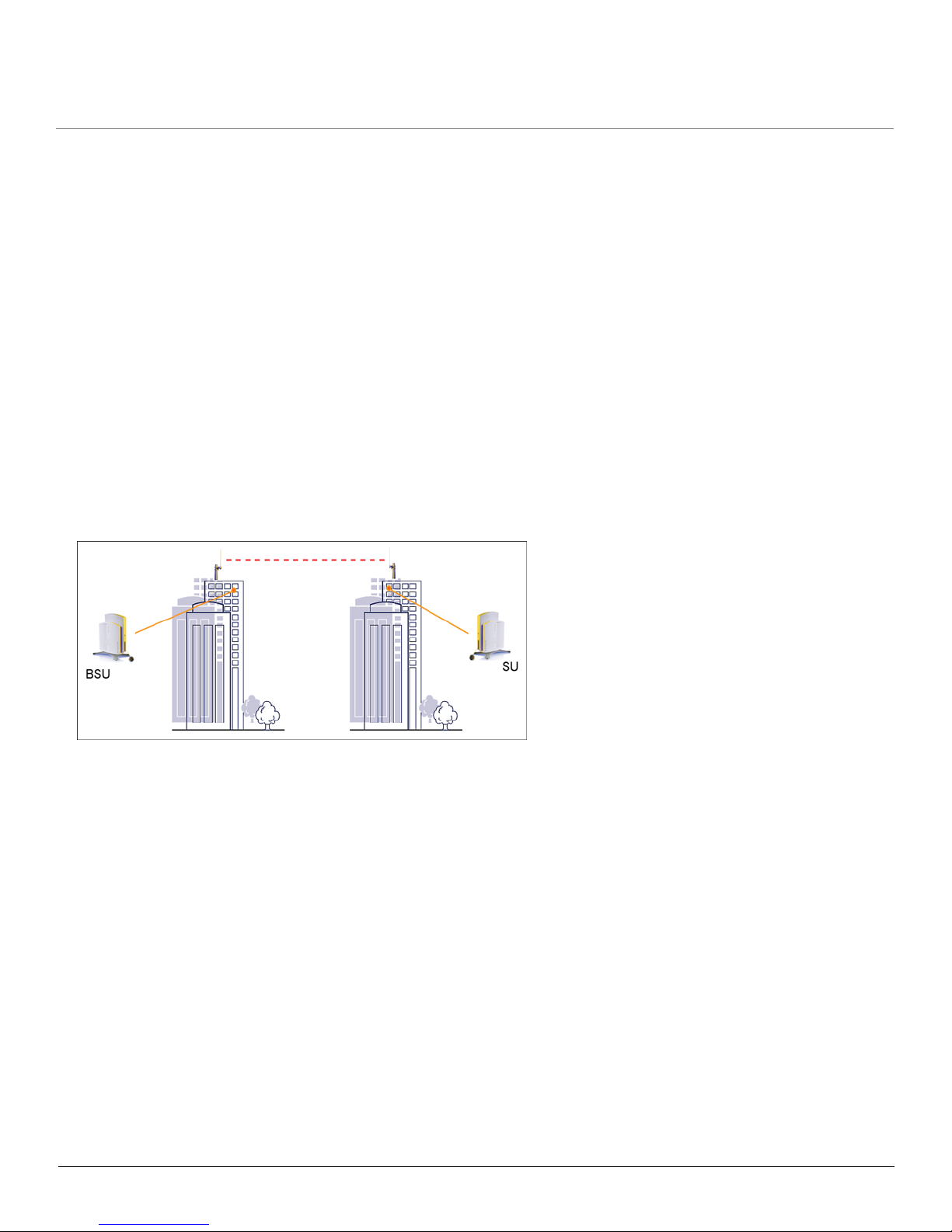
Point-to-Point Link
With a BSU and an SU, it is easy to set up a wireless point-to-point link as depicted in the following figure.
A point-to-point link lets you set up a connection between two locations as an alternative to:
• Leased lines in building-to-building connections
• Wired Ethernet backbones between wireless access points in difficult-to-wire environments
Introduction MP.11 5054 (MP.11a) Installation and Management
Management and Monitoring Capabilities
12
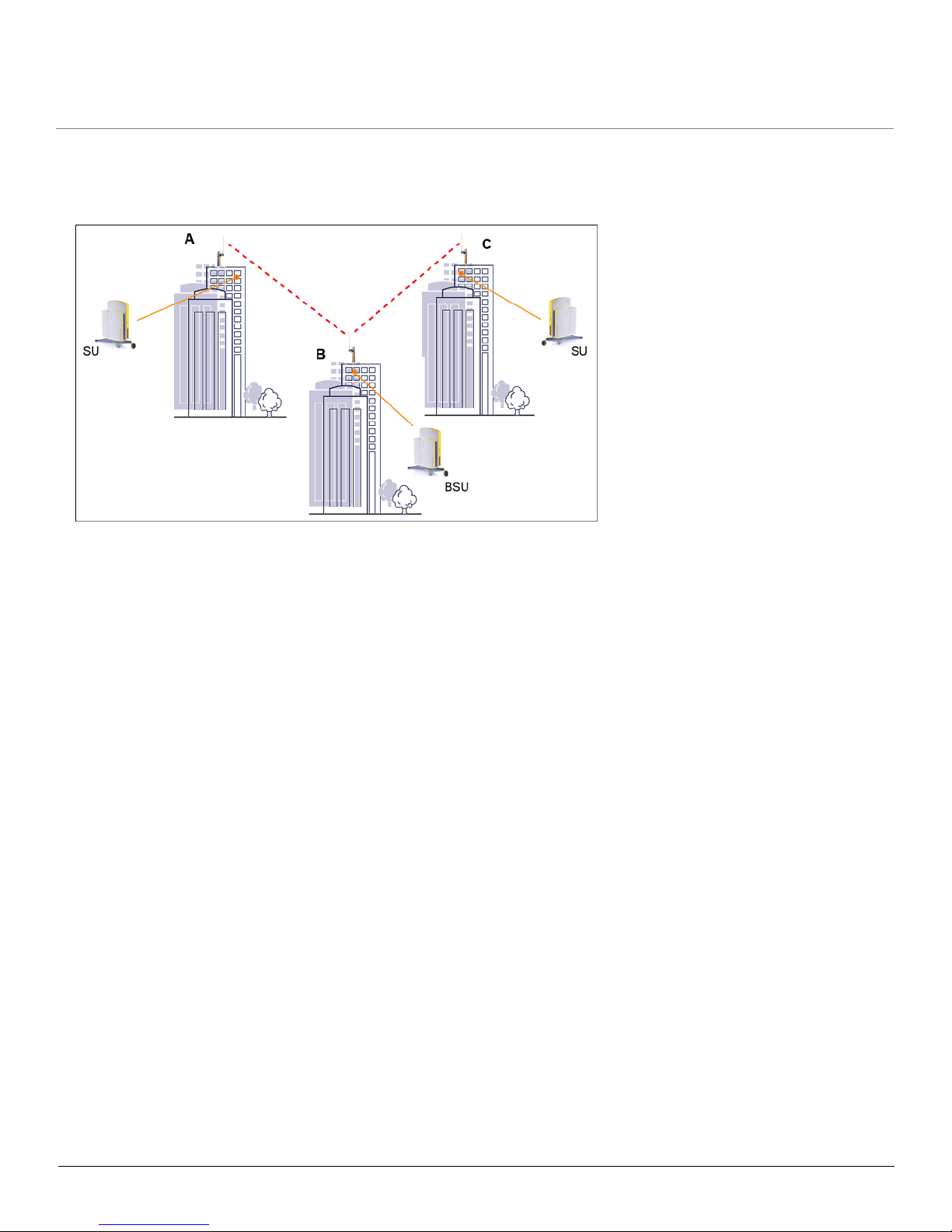
Point-to-Multipoint Network
If you want to connect more than two buildings, you can set up a single point-to-multipoint network with a single BSU and
multiple SUs, as depicted in the following figure.
Up to 250 SUs can be connected to a BSU. If a BSU already has 250 SUs, a new SU cannot be connected to the BSU.
In this figure, the system is designed as follows:
• The central building B is equipped with a BSU, connected to either an omni-directional, or a wide angle antenna.
• The two other buildings A and C are both equipped with an SU connected to a directional antenna.
Management and Monitoring Capabilities
There are several management and monitoring interfaces available to the network administrator to configure and
manage the unit:
• Web Interface
• Command Line Interface
• SNMP Management
Web Interface
The Web interface (HTTP) provides easy access to configuration settings and network statistics from any computer on
the network. You can access the Web interface over your network, over the Internet, or with a crossover Ethernet cable
connected directly to your computer’s Ethernet port. See Logging in to the Web Interface.
Command Line Interface
The Command Line Interface (CLI) is a text-based configuration utility that supports a set of keyboard commands and
parameters to configure and manage the unit. You enter command statements, composed of CLI commands and their
associated parameters. You can issue commands from the keyboard for real-time control or from scripts that automate
configuration. See the Tsunami MP.11/QB.11 Reference Manual for more information about the Command Line Interface.
SNMP Management
In addition to the Web interface and the CLI, you also can manage and configure your unit using the Simple Network
Management Protocol (SNMP). Note that this requires an SNMP manager program (sometimes called MIB browser) or a

Introduction MP.11 5054 (MP.11a) Installation and Management
Management and Monitoring Capabilities
13
Network Manager program using SNMP, such as HP OpenView or Castelrock’s SNMPc. The units support several
Management Information Base (MIB) files that describe the parameters that can be viewed and configured using SNMP:
• mib802.mib
•orinoco.mib
• rfc1213.mib
• rfc1493.mib
• rfc1643.mib
Proxim provides these MIB files on the CD included with your unit. You must compile one or more of these MIB files into
your SNMP program’s database before you can manage your unit using SNMP. See the documentation that came with
your SNMP manager for instructions about how to compile MIBs.
NOTE: When you update the software in the unit, you must also update the MIBs to the same release. Because the
parameters in the MIB may have changed, you will not otherwise have full control over the features in the new
release.
The enterprise MIB (orinoco.mib) defines the read and read/write objects you can view or configure using SNMP. These
objects correspond to most of the settings and statistics that are available with the other management interfaces. See the
enterprise MIB for more information; the MIB can be opened with any text editor, such as Microsoft Word, Notepad, and
WordPad. See SNMP Parameters.
IMPORTANT!
Using a serial connection, you can access the CLI of the unit through a terminal emulation program such as
HyperTerminal. (See “HyperTerminal Connection Properties” in the Tsunami MP.11/QB.11 Reference Manual.)
For all other modes of connection, you will need the IP address of the unit in order to use the Web Interface,
SNMP, or the CLI via telnet. See Setting the IP Address with ScanTool for more information.
IMPORTANT!
The remainder of the User Guide discusses installing the unit and managing it using the Web and CLI
interfaces only. For information on managing the unit via the CLI, see the Tsunami MP.11/QB.11 Reference
Manual.

MP.11 5054 (MP.11a) Installation and Management
14
2
Installation and Initialization
This chapter describes the steps required to install and mount the 5054, including aligning the antenna. The installation
procedure does not include the mounting and connection of antennas. See the Tsunami MP.11 Antenna Installation
Guide for this information.
If you are already familiar with this type of product, you can use the Quick Install Guide for streamlined installation
procedures.
See the following sections:
• Hardware Overview
• Product Package
• Installation Procedure
– Step 1: Choose a Location
– Step 2: Unpack Shipping Box
– Step 3: Attach Base (for Desktop or Ceiling Mounting only)
– Step 4: Remove Covers
– Step 5: Connect the Cables
– Step 6: Mount the Unit
– Step 7: Power on the Unit
– Step 8: View LEDs
– Step 9: Align the Antenna
– Step 10: Attach Kensington Security Lock (Optional)
– Step 11: Install Documentation and Software
• Initialization
– ScanTool
– Setting the IP Address with ScanTool
• Logging in to the Web Interface

Installation and Initialization MP.11 5054 (MP11.a) Installation and Management
Hardware Overview
15
Hardware Overview
The 5054 supports two power methods: an AC power outlet and Power-over-Ethernet. The power supply accepts an
input AC voltage in the range of 100-240 VAC.
Power-over-Ethernet
The unit is equipped with a Power-over-Ethernet (PoE) module. Using PoE, you can provide electricity and wired
connectivity to the unit over a single Category 5 cable. If you use PoE, there is no difference in operation; the only
difference is the power source.
• The PoE integrated module provides -48 VDC over a standard CAT5 Ethernet cable.
• Maximum power supplied to the 5054 is 11 Watts. The units typically draw less than 7.5 Watts.
• You must have an PoE hub (also known as a power injector) connected to the network to use Power-over-Ethernet.
The PoE hub is not a repeater and does not amplify the Ethernet data signal.
• If connected to a PoE hub and an AC power supply simultaneously, the radio draws power from PoE.
• The cable length between the PoE hub and the radio should not exceed 100 meters (approximately 325 feet).
Installation and Initialization MP.11 5054 (MP11.a) Installation and Management
Product Package
16
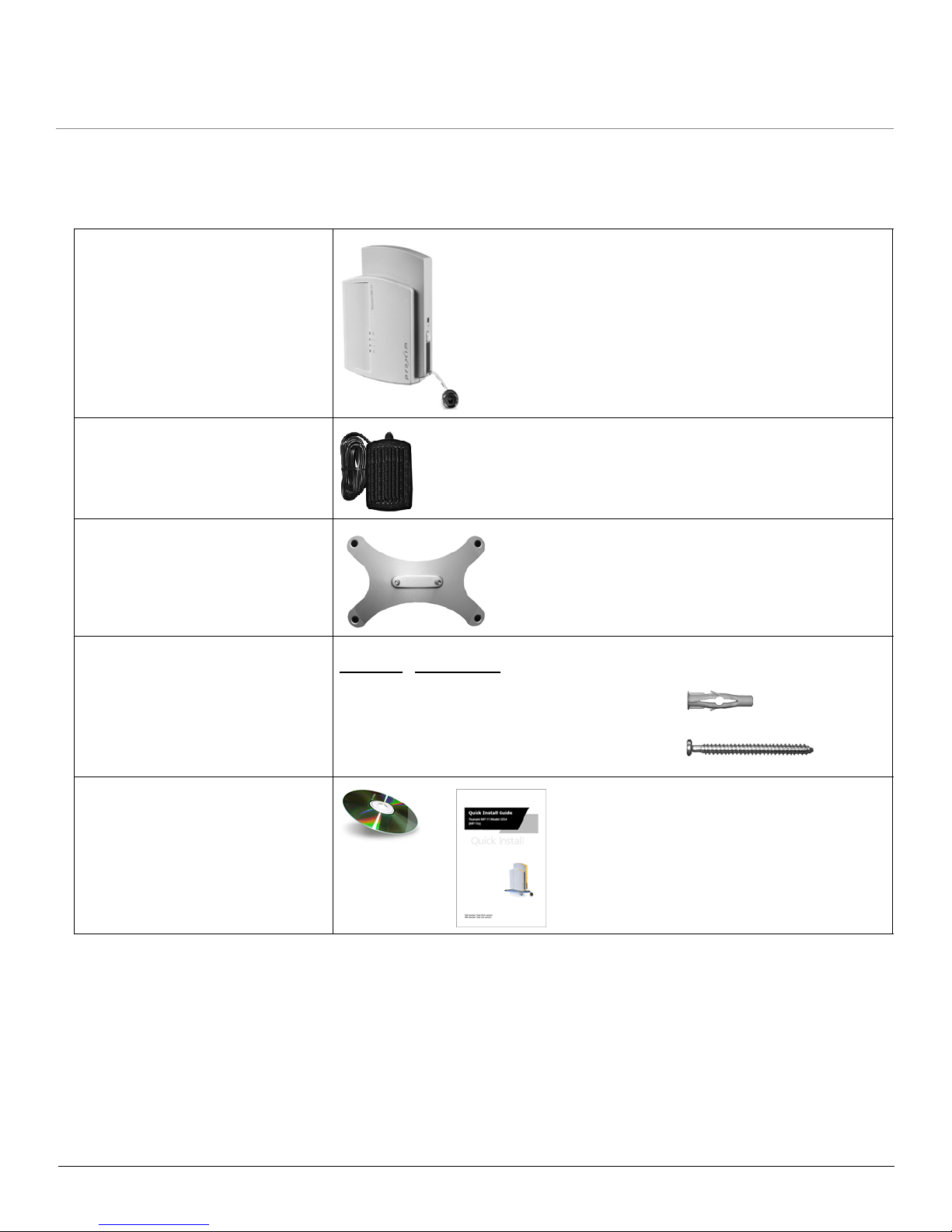
Product Package
Each shipment includes the items in the following table. Verify that you have received all parts of the shipment.
NOTE: Unless noted in this table, cables are not supplied with the unit.
Tsunami MP.11 5054 (MP.11a) unit
Power Adaptor
Mounting Stand
Mounting Hardware
Installation CD and Quick Installation
Guide
Quantity Description
4 ea. Mounting Plug (6 mm x 40 mm)
4 ea. Pan-head Screw (3.5 mm x 40 mm)
Installation and Initialization MP.11 5054 (MP11.a) Installation and Management
Product Package
17
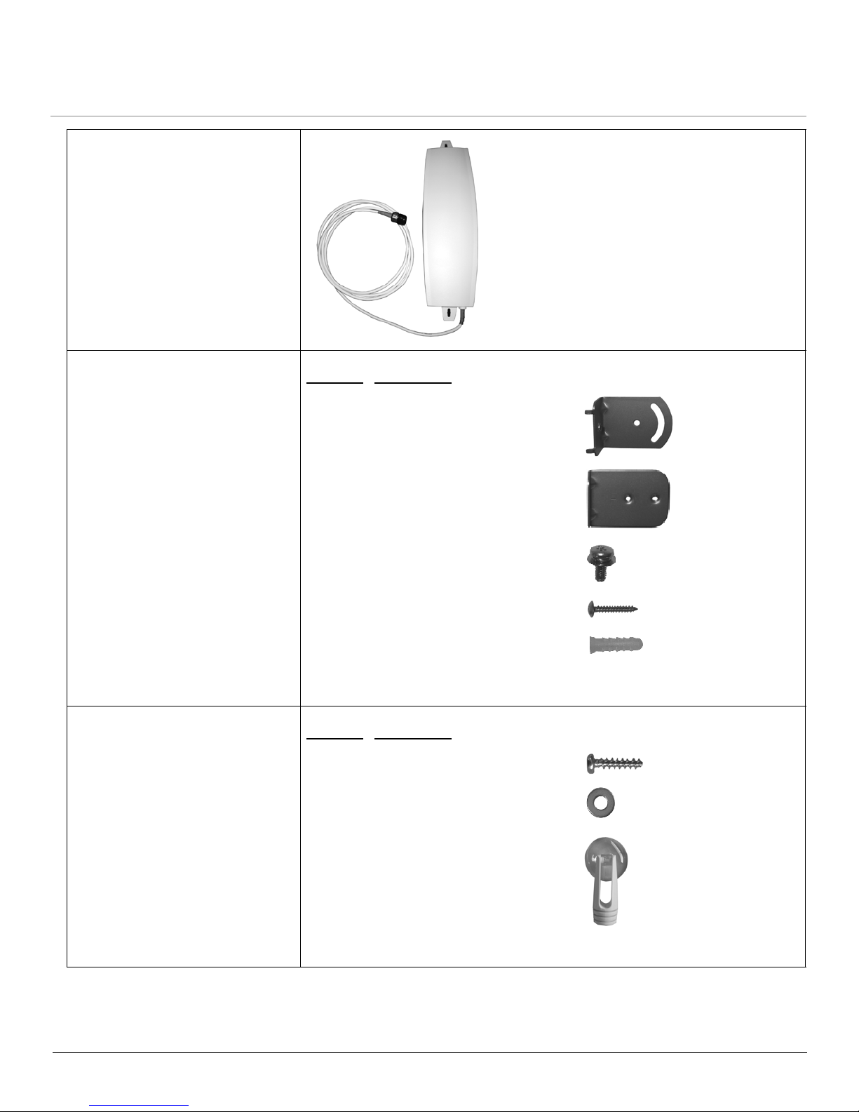
15 dBi Window Antenna (included
with 5054-RSU-xx-WA; available for
order separately)
Outdoor Antenna Mounting
Hardware and Documentation
(included with 5054-RSU-xx-WA)
Indoor Antenna Mounting Hardware
and Documentation (included with
5054-RSU-xx-WA)
Quantity Description
2 ea L-Type Mounting Plate (top)
2 ea L-Type Mounting Plate (bottom)
6 ea. M5 Screw (with washer)
2 ea Screw
2 ea. Wall Mounting Plug (Wall-Tiger)
1 ea. Outdoor Mounting Configuration Flyer
Quantity Description
2 ea Screw
2 ea Washer
2 ea. Suction Cup/Rotation Bar
1 ea. Indoor Mounting Configuration Flyer

Installation and Initialization MP.11 5054 (MP11.a) Installation and Management
Installation Procedure
18
Installation Procedure
NOTES:
• The Configure System window provides a selectable Country field that automatically provides the allowed
bandwidth and frequencies for the selected country as well as, where applicable, Dynamic Frequency Selection
(DFS) and Transmit Power Control (TPC).
• Non-US installers should not add an antenna system until the Country is selected, the unit is rebooted, and the
proper power level is configured.
• Be sure to read the Release Notes file on the product CD as it contains software version and driver information
that may not have been available when this document was produced.
• When using PoE, use only a power injector that meets these requirements:
– UL-Listed/ITE (NWGQ)
– Limited Power Source Output per UL/IEC 60950
– CE-marked
– Approved for Power-over-Ethernet
– Rated output, 48 Vdc/0.42 A
– Pinout follows 802.3af standard for mid-span devices
The following installation procedure provides instructions for attaching both the power and Ethernet connectors. In
situations without an external antenna (for example, during a desk tryout), the antenna cable is not required.
See the following steps:
• Step 1: Choose a Location
IMPORTANT:
Before installing and using this product, see Safety and Regulatory Compliance Information on the
product CD.
IMPORTANT:
All units must be installed by a suitably trained professional installation technician or by a qualified
installation service.
WARNING:
For your own safety, when using DC power, use only the power adaptor supplied with the unit.
WARNING:
The metal case of the unit must be grounded through the ground connection that is provided on the
metal case. The antenna grounding, the surge arrestor, and the 5054 unit housing must be bonded
together and grounded in one location to avoid ground current loops.

Installation and Initialization MP.11 5054 (MP11.a) Installation and Management
Installation Procedure
19
• Step 2: Unpack Shipping Box
• Step 3: Attach Base (for Desktop or Ceiling Mounting only)
• Step 4: Remove Covers
• Step 5: Connect the Cables
• Step 6: Mount the Unit
• Step 7: Power on the Unit
• Step 8: View LEDs
• Step 9: Align the Antenna
• Step 10: Attach Kensington Security Lock (Optional)
• Step 11: Install Documentation and Software

Installation and Initialization MP.11 5054 (MP11.a) Installation and Management
Installation Procedure
20
Step 1: Choose a Location
To make optimal use of the 5054, you must find a suitable location for the hardware. The range of the unit largely
depends upon the position of the antenna. Proxim recommends you do a site survey, observing the following
requirements, before mounting the 5054 hardware.
• The location must allow easy disconnection of the unit from the power outlet if necessary.
• The unit must not be covered and the air must be able to flow freely around the unit.
• The unit must be kept away from vibration, excessive heat, and humidity, and kept free from dust buildup.
• The installation must conform to local regulations at all times.
CAUTION: Proxim recommends the use of a lightning arrestor at the building ingress point. You can purchase the
Proxim Lightning Protector; see the documentation that comes with the Lightning Protector for more
information and installation instructions.
Step 2: Unpack Shipping Box
1. Unpack the unit and accessories from the shipping box.
2. Note the Ethernet and MAC addresses of the unit, as well as the serial number; these addresses may be used when
configuring the unit.
NOTE: The serial number is required to obtain support from Proxim. Keep this information in a safe place.
Installation and Initialization MP.11 5054 (MP11.a) Installation and Management
Installation Procedure
21
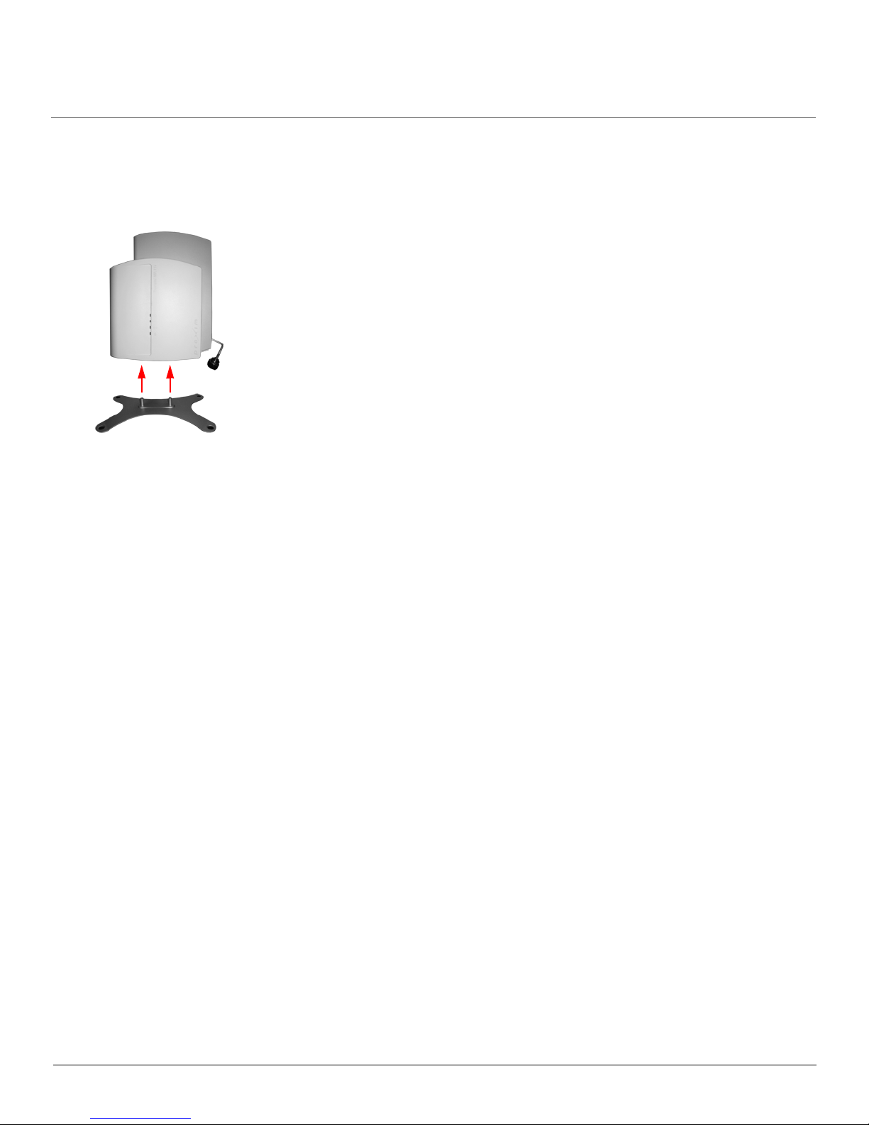
Step 3: Attach Base (for Desktop or Ceiling Mounting only)
If the unit will be mounted on a desktop or to a ceiling, attach the metal base as follows. If the unit will be mounted to a
wall, proceed to Step 4: Remove Covers.
1. Insert the posts in the metal base into the holes on the bottom of the 5054 unit.
2. Using a Phillips-head screwdriver, tighten the screws on the bottom of the metal base to securely attach the base to
the unit.

Installation and Initialization MP.11 5054 (MP11.a) Installation and Management
Installation Procedure
22
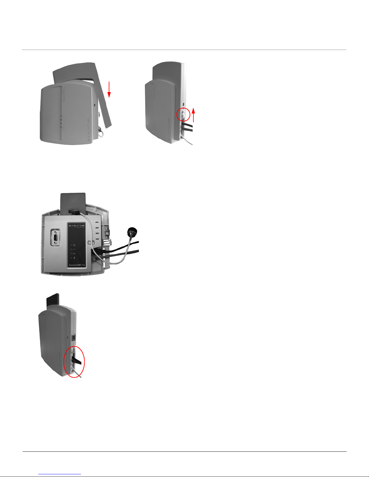
Step 4: Remove Covers
In order to cable the unit for operation, you must first remove the front, back, and cable covers.
1. Unlock the unit’s cable cover by pressing down on the cable cover lock located on the side of the unit.
2. Pull the thin arm of the cable cover away from the unit and upward to remove the cable cover.
3. Remove the front cover from the unit (the side with the LED indicators, shown in figure A); then remove the back
cover (figure B). The unit with all covers removed is shown in figure C.
CBA
Installation and Initialization MP.11 5054 (MP11.a) Installation and Management
Installation Procedure
23
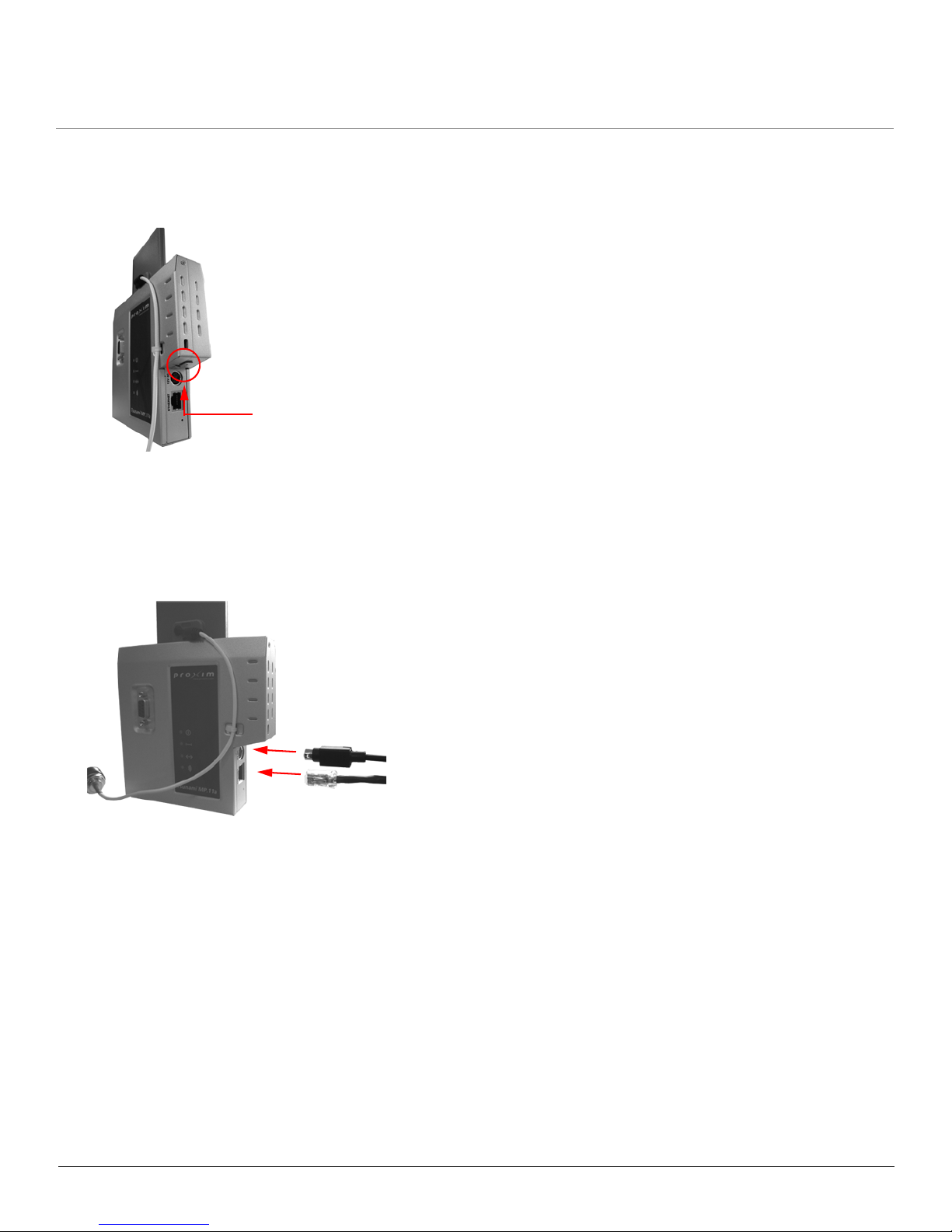
Step 5: Connect the Cables
1. Identify the location at which you intend to mount the unit.
2. Connect the grounding wire to the 5054 using the Faston plug on the metal case, next to the power plug.
3. Connect one end of an Ethernet cable to the Ethernet port.
• If you intend to connect the 5054 to a hub, switch, patch panel, or PoE power injector, use a straight-through
Ethernet cable.
• If you intend to connect the 5054 to a single computer, use a cross-over Ethernet cable.
4. If you are not using Active Ethernet, or you want to connect the 5054 to Active Ethernet and AC power simultaneously, attach the AC power cable to the unit’s power port.
Location of Faston plug
Power
Ethernet
Installation and Initialization MP.11 5054 (MP11.a) Installation and Management
Installation Procedure
24
Step 6: Mount the Unit
• Desktop Mount
• Wall Mount
• Ceiling Mount
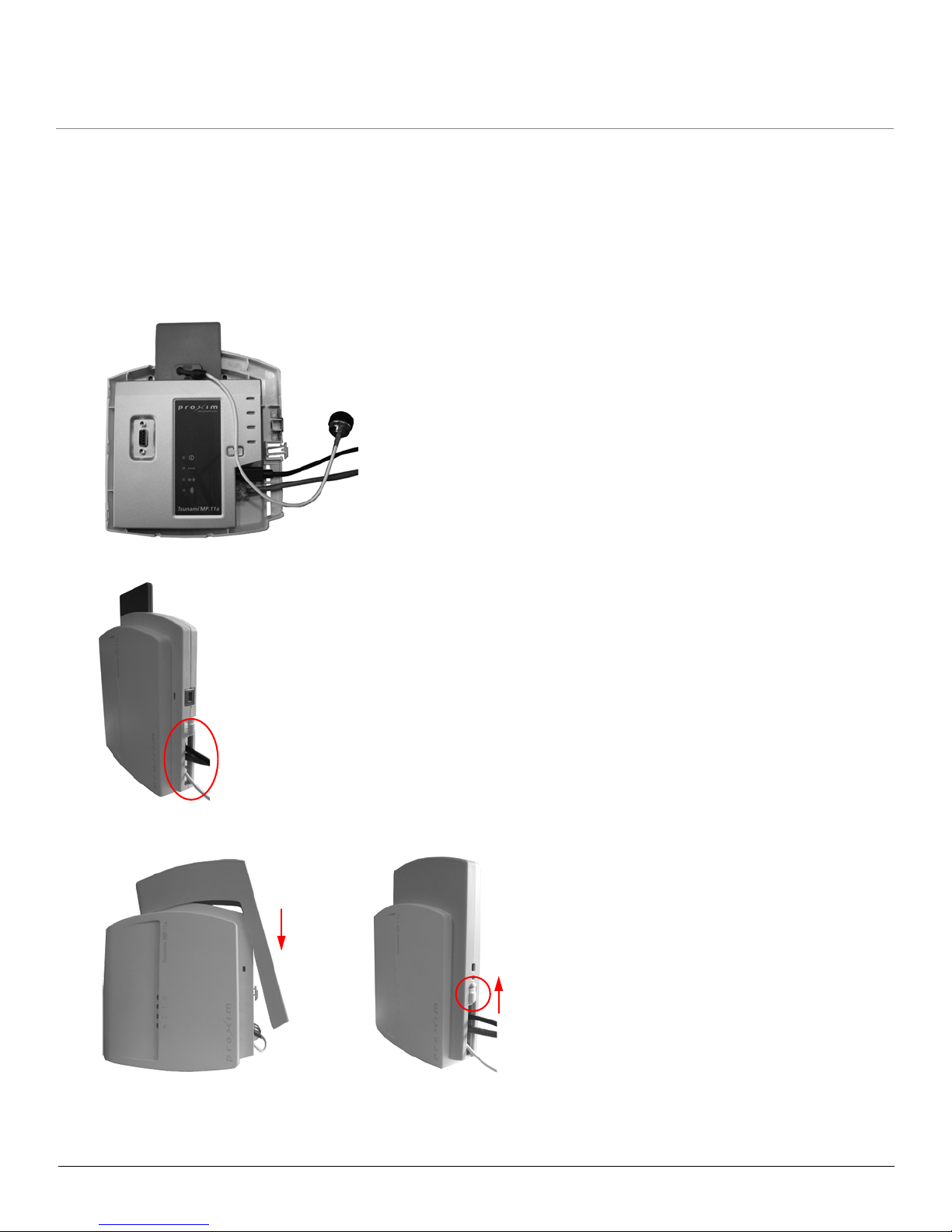
Desktop Mount
1. Fit the radio inside the back cover, with the serial connection and LED indicators facing out.
2. Replace the front cover, threading the cables through the opening at the lower right side of the cover.
3. Replace the cable cover (figure A), ensuring that the release latch clicks upwards to the closed position (figure B).
4. If you have not done so before, attach the metal base as described in Step 3: Attach Base (for Desktop or Ceiling
Mounting only).
BA
Installation and Initialization MP.11 5054 (MP11.a) Installation and Management
Installation Procedure
25
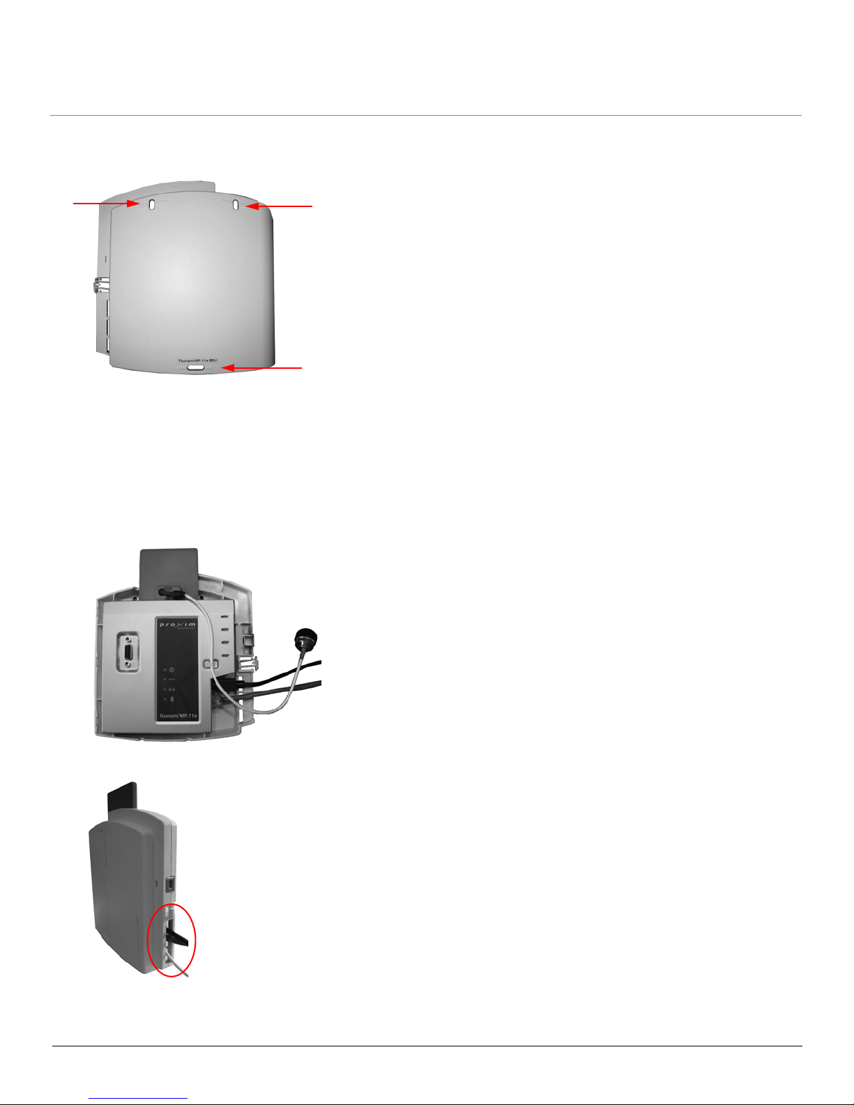
Wall Mount
1. Place the back cover on the mounting location and mark the center of the three mounting holes.
2. Remove the cover from the wall and drill a hole at each of the locations you marked. Each hole should be wide
enough to hold a mounting plug (6 mm x 35 mm).
3. Insert a plug into each hole. (Four 6 mm x 35 mm plugs are provided; you need to use only three of these for wall
mounting.)
4. Insert a screw into each of the mounting holes molded into the back cover, and align with the holes on the wall. (Four
3.5 mm x 40 mm pan-head screws are provided; you need to use only three of these for wall mounting.)
5. Use a screwdriver to tighten the screws, attaching the back cover to the wall.
6. Fit the radio inside the back cover, with the serial connection and LED indicators facing out.
7. Replace the front cover, threading the cables through the opening at the lower right side of the cover.
8. Replace the cable cover (figure A), ensuring that the release latch clicks upwards to the closed position (figure B).
Mounting holes
Installation and Initialization MP.11 5054 (MP11.a) Installation and Management
Installation Procedure
26
Ceiling Mount
1. Fit the radio inside the back cover, with the serial connection and LED indicators facing out.
2. Replace the front cover, threading the cables through the opening at the lower right side of the cover.
3. Replace the cable cover (figure A), ensuring that the release latch clicks upwards to the closed position (figure B).
BA
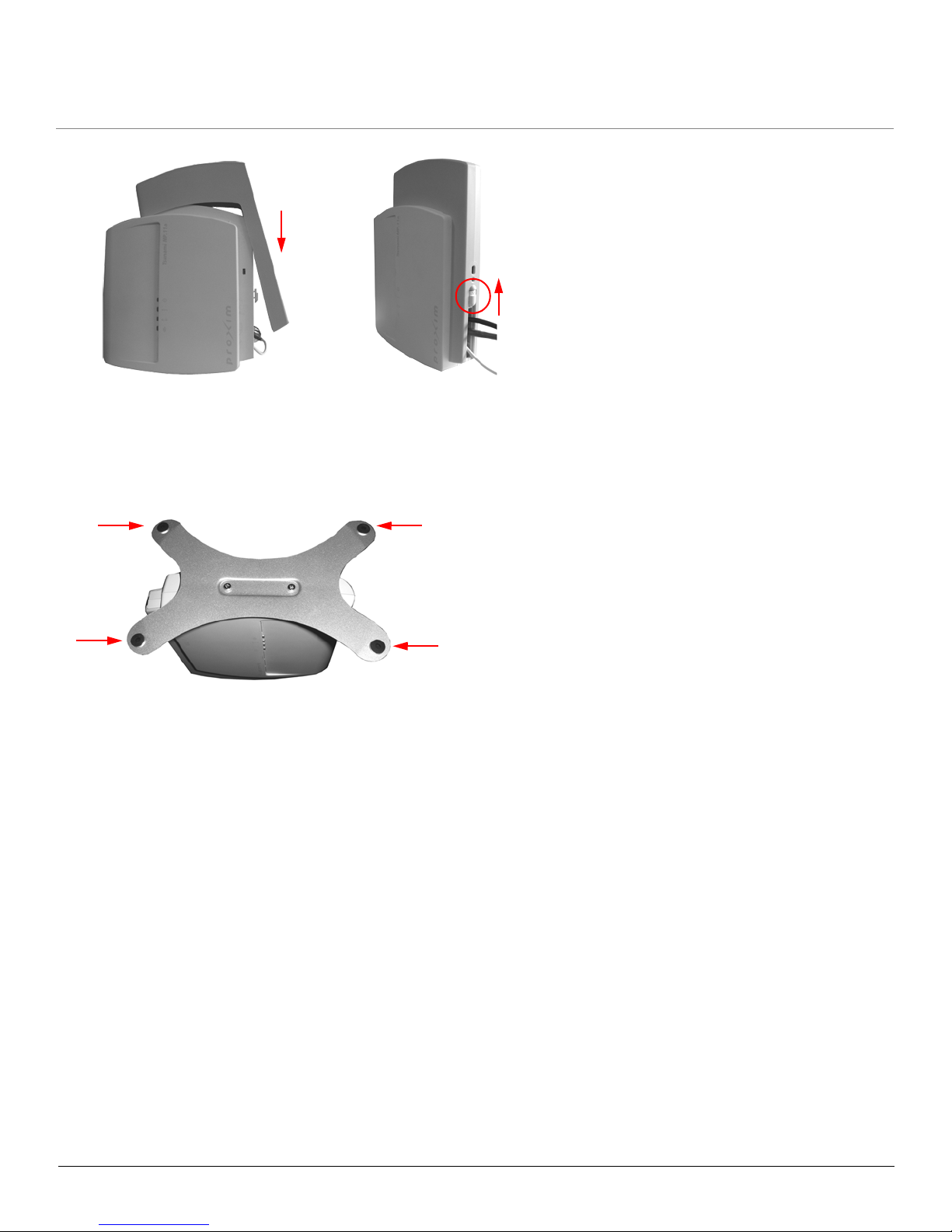
Installation and Initialization MP.11 5054 (MP11.a) Installation and Management
Installation Procedure
27
4. If you have not done so before, attach the metal base as described in Step 3: Attach Base (for Desktop or Ceiling
Mounting only).
5. Feed a mounting screw through each of the four rubber feet. The 5054 comes with four 3.5 mm x 40 mm pan-head
screws.
6. Remove the screws from the rubber feet.
7. With the 5054 turned upside down, position the base against the ceiling where you want to mount the unit.
8. Mark the center of the four mounting holes in the rubber feet.
9. Set the 5054 aside and drill a hole at each of the locations you marked. Each hole should be wide enough to hold a
mounting plug (6 mm x 35 mm).
10. Insert a plug into each hole. The 5054 comes with four 6 mm x 35 mm plugs.
11. Insert the screws into the holes you made previously in the rubber feet.
12. Insert the screws into the mounting plugs.
13. Use a screwdriver to tighten the screws, attaching the 5054’s metal base to the ceiling.
BA
Rubber feet
Installation and Initialization MP.11 5054 (MP11.a) Installation and Management
Installation Procedure
28
Step 7: Power on the Unit
The 5054 can be powered by a power supply (just plug the power cord of the power supply into an AC power outlet), or
by PoE (connect a PoE splitter to the Ethernet cabling).
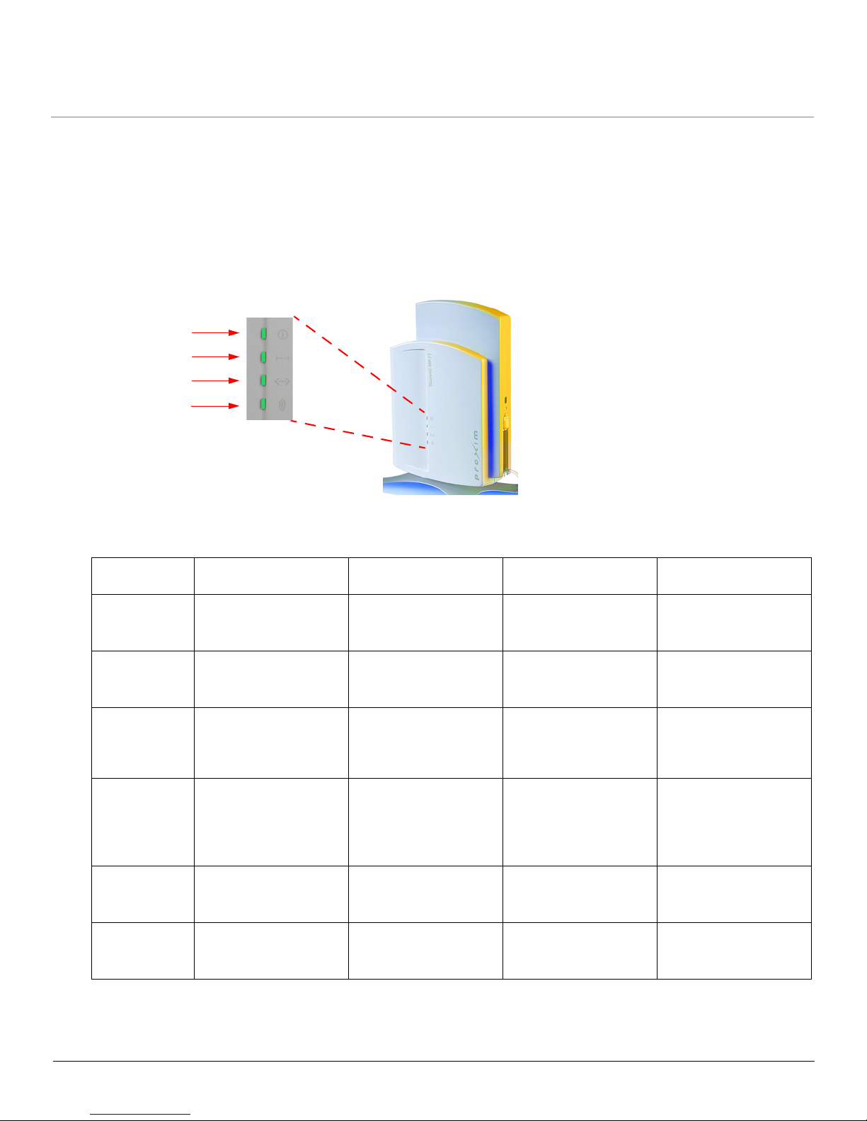
Step 8: View LEDs
When the unit is powered on, the 5054 performs startup diagnostics. When startup is completed, the LEDs show the
operational state of the 5054 (see the following figure).
The following table shows the status of the LEDs when the 5054 is operational (the fourth LED is only used during
Dynamic Frequency Selection on a BSU).
LED Power Ethernet Link Wireless Link Dynamic Frequency
Selection
Off Power is not present or
is malfunctioning.
Not connected. Wireless interface is up
properly but no wireless
link established.
Green Power is present; the
unit is operational.
Connected at 10 Mbps. Immediately after
connecting a wireless
link.
Blinking Green N/A Data is being sent at 10
Mbps.
Data is being sent or
the wireless interface is
initializing after reboot
(less than two minutes).
Scanning for channel.
Amber The unit is initializing
after reboot (less than
two minutes); it cannot
get a dynamic IP
address.
Connected at 100
Mbps, or the unit is
initializing after reboot
(less than two minutes).
N/A N/A
Blinking Amber N/A Data is being sent at
100 Mbps.
N/A N/A
Red A fatal error in the unit. An error in data
transfer.
There is a fatal error on
the wireless interface.
N/A
Power
Ethernet Link
Wireless Link
Dynamic
Frequency
Selection

Installation and Initialization MP.11 5054 (MP11.a) Installation and Management
Installation Procedure
29
Step 9: Align the Antenna
Antenna alignment is the process of physically aligning the antenna of the radio receiver and transmitter to have the best
possible link established between them. The antenna alignment process is usually performed during installation and after
major repairs.
Antenna Alignment Display (AAD) provides a measurement of signal quality in an easy-to-interpret manner—a numeric
printed signal value at the CLI and serial ports. The SNR is numerically displayed on the CLI or serial port by two decimal
characters representing a number from 00 to 99. On the serial port, AAD is enabled by default after booting.
To start the display, you must enable AAD and a wireless link must be established between the BSU and the SU.
Aiming is complete if moving in any direction results in a falling SNR value.
NOTES:
• Antenna alignment for the Base Station is useful only for a point-to-point link.
• The Antenna Alignment Display (AAD) CLI command is disabled automatically 30 minutes after it is enabled to
remove the load of extra messages on the wireless interface. The default telnet timeout is 900 seconds (15
minutes). If AAD must run for the entire 30 minutes, change the default telnet timeout value to a value greater
than 30 minutes (greater than 1800 seconds). This restriction is for telnet connections only and not for the serial
interface. The serial interface never times out; however, the AAD command does still time out.
Antenna Alignment Commands
• set aad enable local: Enables display of the local SNR. Local SNR is the SNR measured by the receiver at the
near end.
• set aad enable remote: Enables display of the remote SNR. Remote SNR is the SNR as measured by the
receiver at the far end.
• set aad enable average: Enables display of the average SNR. The average SNR is the average of the local and
remote SNR.
• set aad disable: Disables Antenna Alignment Display (Ctrl-C also disables AAD).
Installation and Initialization MP.11 5054 (MP11.a) Installation and Management
Installation Procedure
30
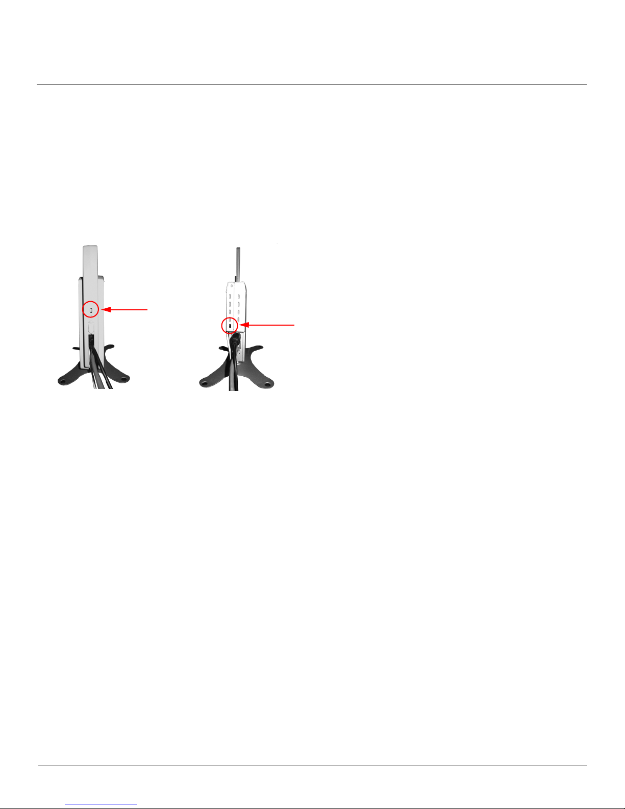
Step 10: Attach Kensington Security Lock (Optional)
If desired, you can attach a Kensington lock to secure the cable cover into place. This protects the unit from unauthorized
tampering.
The 5054 enclosure includes a Kensington Security Slot for use with a Kensington locking mechanism. When properly
installed, a Kensington lock can prevent unauthorized personnel from stealing the 5054. In addition, the Kensington lock
secures the cable cover in place, which prevents tampering with the Ethernet and power cables.
The Kensington Security Slot is shown in the following figures. Figure A shows the slot with the unit’s covers attached;
figure B shows the slot with the unit’s covers removed).
For information about Kensington security solutions, go to http://www.kensington.com.
A
B
 Loading...