

Page 1
TSUJI ELECTRONICS CO.,LTD
3739 Kandatsu-machi Tsuchiura-city
Ibaraki-Pre 300-0013 Japan
Phone +81-(0)29-832-3031
Fax +81-(0)29-832-2662
URL http://www.tsujicon.jp
E-mail info2@tsuji-denshi.co.jp
APPLICATION OF ELECTRONIC DEVICES
100MHz VF CONVERTER
N2VF-1H
USER'S MANUAL
#3503 (rev.1) 2016.06.10
Page 2
1. Feature
N2VF-1H is the 100MHz 2CH V-F Converter that is housed in a NIM-1UNIT case. It has the four-levels
amplification factor switch and the polarity selector switch.
N2VF-1H is easy to be monitored.
i.e., the over-range and polarity are displayed on LED and also outputted as open-collector outputs.
Therefore, V-F conversion is always performed at the optimum conditions.
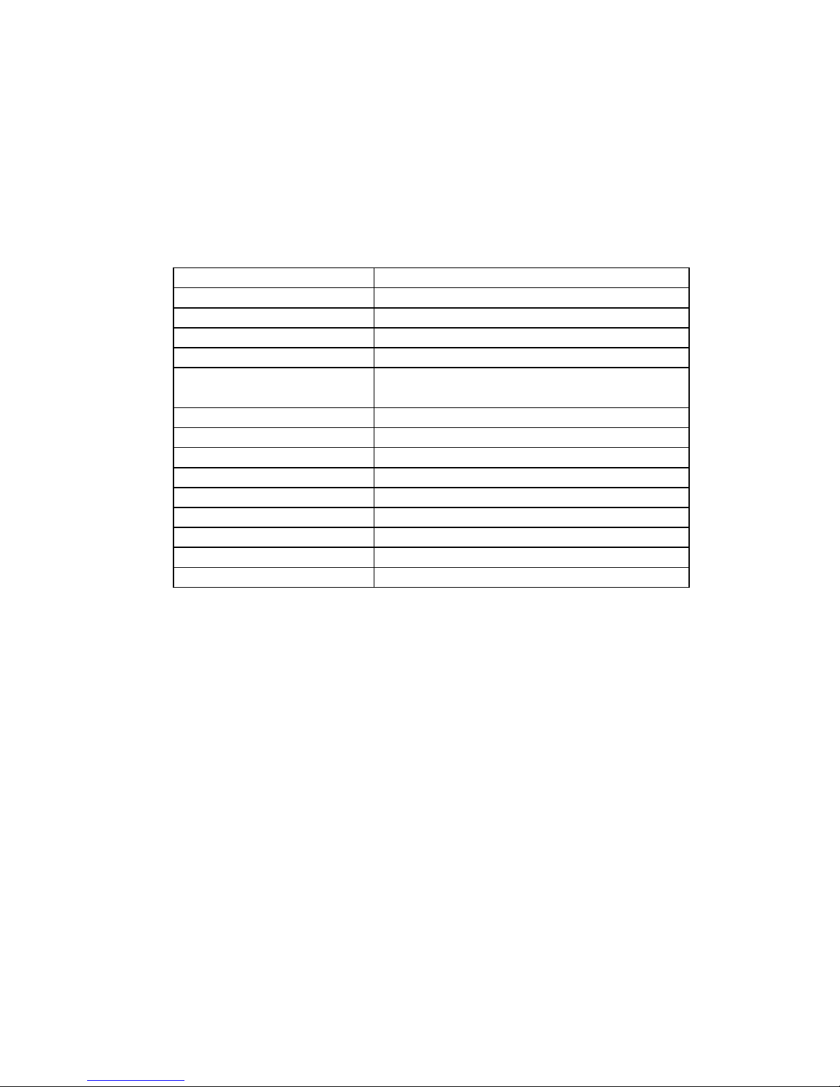
2. Specification
3. Before using
Before using, please power about 2 hours on for a warm-up.
The frequency deviation becomes large, if warm-up has not been made.
±0.01% FS
1MHz
10μs or less
BNC connector
LEMO connector (equivalent to EPL00250NTN)Output Connector for Frequency
Over-Range output
NIM-1UNIT
Over-Range output Connector
Power supply
Case
Open collector (normaly close), isolated
BNC connector
+12V/200mA, +6V/600mA
Conversion Accuracy
Input Impedance
Inpur Sampling Frequency
Response
Input Connector
Output
TTL level
※ Please use 50Ω termination to reduce the reflected wave.
100MHz VF converter N2VF-1H
User's Manual [Rev.1]
Channels
Input Range
Output Range
2CH
-10V/-5V/-2.5V/-1V/+1V/+2.5V/+5V/+10V
100MHz/50MHz/25MHz/10MHz
1MΩ
Input Single-end
Page 1 / 3
Page 3

4. Usage
4-1. Front panel
① CH1 Scale over LED
LED lights on when the input level exceeds conversion level.
② CH1 Input polarity LED
LED lights on if the voltage input polarity is different from the setting.
③ CH1 Input voltage range select SW
Select input voltage range.
④ CH1 Output frequency range select SW
Select output frequency range.
⑤ CH2 Scale over LED
LED lights on when the input level exceeds conversion level.
⑥
CH2 Input polarity LED
LED lights on if the voltage input polarity is different from the setting.
⑦
CH2 Input voltage range select SW
Select input voltage range.
⑧ CH2 Output frequency range select SW
Select output frequency range.
⑨ CH1 Input connector (voltage, BNC)
⑩ CH1 Polarity select slide-SW
NOM: (+), REV: (-)
⑪ CH2 Input connector (voltage, BNC)
⑫ CH2 Polarity select slide-SW
NOM: (+), REV: (-)
⑬
CH1 Output connector (frequency, LEMO, LVTTL level)
⑭
CH2 Output connector (frequency, LEMO, LVTTL level)
①
②
③
④
⑥
⑦
⑧
⑤
⑨
⑪
⑬
⑭
⑩
⑫
Page 2 / 3
Page 4

4-2. Rear panel
① CH1 Scale over output connector (BNC)
Open collector output. It is isolated from the internal circuit.
Output becomes off if the voltage input is over than the setting.
(normaly close)
② CH2 Scale over output connector (BNC)
Open collector output. It is isolated from the internal circuit.
Output becomes off if the voltage input is over than the setting.
(normaly close)
③ Changeover switch for choosing isolation or common between
NIM GND and the internal circuit GND.
FLOTING: isolation, G.COMMON: common
①
②
③
Page 3 / 3
 Loading...