

USER’S MANUAL
E N G L I S H
TSPROF K-02
Knife Sharpener

2

3
Table of Contents
Table of contents ......................................................................................3
Safety guide ..............................................................................................4
Maintenance tips ......................................................................................5
Components list .......................................................................................7
Assembling ...............................................................................................7
Installation .................................................................................................8
Base unit assembling .........................................................................10
Abrasive Holder assembling ...............................................................11
Installation of the Clamps ......................................................................13
Adjustment of the rotary gear ! xation effort .......................................13
Installation of the Single Clamp ..........................................................14
Installation of the Double Clamp ........................................................15
Installation of an abrasive .....................................................................16
Calibration of the Sharpening system and Clamps ............................17
Calibration of horizontal frame Method 1 ...........................................18
Calibration of horizontal frame Method 2 ...........................................21
Turning Clamp angle calibration .........................................................24
Digital gauge platform horizontal calibration ......................................29
Digital gauge platform parallel calibration ..........................................32
Knife installation .....................................................................................34
Knife installation into the Single Clamp ..............................................34
Knife installation into the Double Clamp ............................................36
Full " at grind clamping .......................................................................37
Calibration of the in-built gauge ...........................................................40
Sharpening angle adjustment ............................................................43
Bar stoppers adjustment ....................................................................45
Bar parking..............................................................................................48

4
Safety guide
• Sharpening greatly increases the risk of injury from contact with a blade,
even a slight touch of the sharpened blade can lead to a severe cut.
• During the sharpening, beware of contact with a blade. Bear in mind that
translational movements are made towards a sharp blade.
• Before starting the sharpening process, be sure to install the bar stoppers.
• When installing, adjusting and during the sharpening work, protect your
hands from cuts on the sharp edges of a knife.
• After • nishing work with the sharpening system, remove the knife from the
clamp (or together with the clamping jaws) and put it into the sheath, or
otherwise isolate the blade to avoid cuts.
• During the sharpening work, beware of accidental triggering of the rotary
gear, for example, when the • xation effort is exceeded.
• When using a G-clamp to secure the body of the sharpening system to a
table or workbench, make sure that the G-clamp is well tightened and the
body is securely • xed to the work surface.
• When using the stand, hold the sharpener at a distance from the edge of
the working surface. The fall of heavy metal construction even from a small
height can lead to injuries.
• Do not leave an open, not covered blade in the access zone of children
and animals.
WARNING
• Before using, read this user’s manual to ensure correct usage through
understanding. After reading, store it in a safe place for future reference. Incorrect handling of this product could possibly result in personal
injury or physical damage. The manufacturer assumes no responsibility
for any damage caused by mishandling that is beyond normal usage
de• ned in this sharpening system manual.

5
• Moving the abrasive holder bar during the process of sharpening should
be smooth and even, without any jerky motions and too much of a hand
force applied.
• When the sharpening is • nished, remove the holder bar, abrasive and a
knife. Clean the sharpening system with a dry napkin.
Maintenance:
1. Keep your workspace and the sharpening system clean. Wipe the dust and
dirt away from the working surfaces and moving components.
2. Change the worn-out components as required.
3. The sharpening system should always be checked before using. All the
disrepair should be • xed and the calibration is done. Check the smoothness
of all moving components.
4. Working surfaces should be dry and slightly oiled.
5. Check the condition and position of all the mounts, details and components
after 50 hours of use.
6. For smearing the connected parts use a machine oil.
7. Damage and wear and tear of the screwed joints. Especially on the
holding screws of the spring clamp. As a preventative care of this issue,
we recommend not to use the screws without any lube and keep the right
order of manipulating them. (E.g. Full fl at grind clamping at page 35). If
some holding screws are got damaged, unscrew and change them. But
before unscrewing them, grind the end of the screw off, just because it can be
squashed during the work. Do not apply much force when unscrewing during
the repair operation because it damage the clamp threads.
8. If you have any dif• culties with repair, address to the product vendor.
Maintenance tips

6
1. Body
2. Stand
3. Vertical angle bar with gauge
4. Abrasive Holder
5. Single Clamp
6. Double Clamp
7. G-clamp
8. Spare parts

7
Assembling
TSPROF K02 Knife Sharpener Components List

8
Installation method - 1
1. Stick softening spacers from the spare parts to the G-clamp contact sur-
faces.
2. Attach the body to a table using the G-clamp.

9
Installation method - 2
1. Stick 5 self-adhesive silicone feet from the spare parts to the underside of
the stand.
2. Place the sharpener body into the hollow part of the stand. Attach by
tightening the thumbscrews. The stand should be placed on a fl at stable
surface at some distance from a table edge.

10
1. Loosen the thumb-
screw ! xing the vertical
bar.
2. Lubricate the vertical
bar with a drop of a liquid grease and install it.
Base unit assembling

11
1. Assemble the abrasive holder.
Abrasive Holder assembling
3. Tighten the thumb-
screw ! xing the
vertical bar.

12
2. Remove the outermost stopper and its bumper.
3. Lubricate the guide with a drop of a liquid grease and install the abrasive
holder into the vertical bar bush.

13
4. Install the bumper and the stopper back to their places.
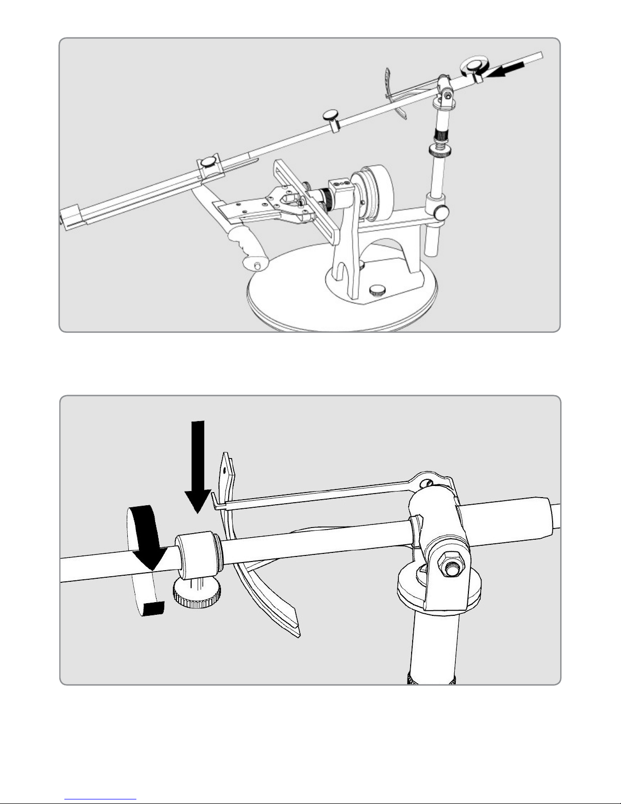
Adjustment of the rotary gear fi xation eff ort
1. By turning the calibration wheel, set a necessary rotary gear ! xation effort. Choose an effort so it doesn’t " ip during the process of sharpening.
Note:
You should tighten the
calibration wheel only with your
hands, tightening too much may
damage the rotary gear.
Note:
Be aware of rotary gear triggering when the force is applied to a
blade during the process of sharpening.
Note:
For increasing the fi xation effort,
turn the rotary gear clockwise
(as shown in the fi gure 2), for
decreasing - counter-clockwise.
14
Installation of the Single Clamp
2. Turn the rotary gear clockwise.
1. Install the clamp into the frame and tighten it with the ! xing screws.

15
1. Install the clamp jaws into the frame. Slightly tighten the ! xing screws.
Installation of the Double Clamp
2. Adjust the jaws position according to the length and geometry of a knife
blade and tighten the ! xing screws.

16
Installation of an abrasive
1. Loosen the fi xing thumbscrew on the second thrust bar.

17
2. Moving the second thrust bar, set the distance between the thrust bars to
10 - 12mm less than the abrasive length. Tighten the fi xing thumbscrew
on the second thrust bar.
3. Pulling the fi rst thrust bar towards the handle, squeeze the spring and
insert the abrasive.
Calibration of the Sharpening system
and Clamps
WARNING! Be carefull performing the calibrations described
in this manual, incompetent or careless actions can lead to
breakage of the mechanisms of the sharpening system.

18
Required tools: spanners - 7mm, 10mm and 24mm, hex keys - 2mm, 2.5mm
or torx - t8, t10.
If an angle deviation is <= 0.3° (or other value of required accuracy), then an
adjustment is not needed. Minor deviation calibration is not recommended.
All the calibrations should be performed on a rigid stable surface.
Calibration of horizontal frame - Method 1
1. By turning the calibration wheel, set a slight rotary gear ! xation effort.
2. Place the digital gauge on the sharpener’s base unit and reset its value.

19
4. Holding the frame clutch with a 24mm spanner, loosen the fi xing nut with a
10mm spanner.
3. Place the digital gauge on the frame. If the gauge shows a deviation of <=
0.3° (or other value of required accuracy), adjustment is not needed.
Next steps are needed to perform the calibration.

20
6. Holding this position with a 24mm spanner, tighten the fi xing nut with a
10mm spanner.
5. By turning the frame, adjust its position.

21
Calibration of horizontal frame - Method 2
Tools required: a ruler, spanners - 24mm and 10mm.
1. By turning the calibration wheel, set a slight rotary gear fi xation effort.
2. Position a ruler straight vertically. Measure the distance from the ends of
the frame to a table.

22
4. By turning the frame, adjust its position so the measured distances are
about equal.
3. Holding the frame clutch with a 24mm spanner, loosen the fi xing nut with a
10mm spanner.

23
5. Holding this position with a 24mm spanner, tighten the fi xing nut with a
10mm spanner.

24
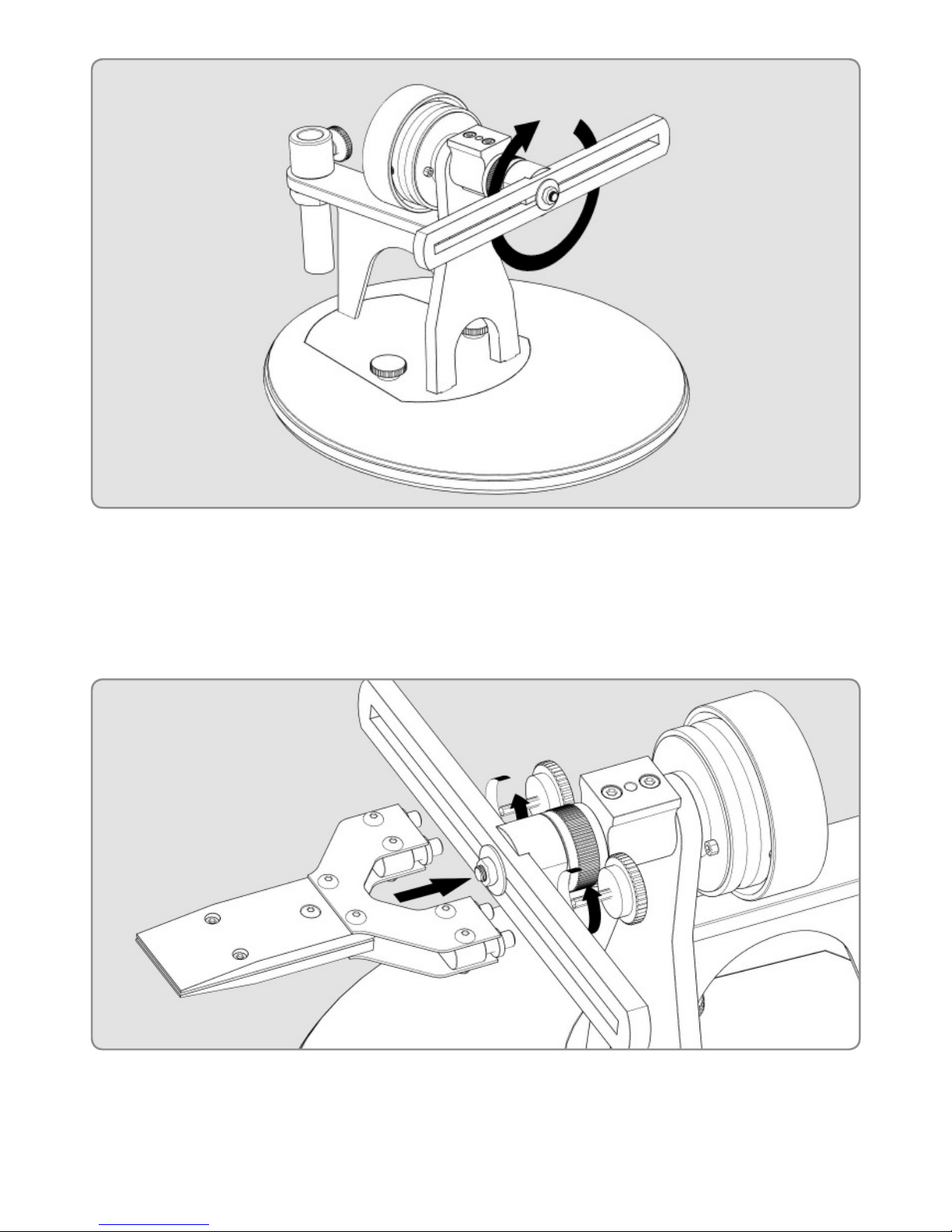
Calibration should be made to eliminate angle asymmetry when the clamp
rotates, which may emerge during transportation or after a long operation
period.
Tools required: a digital gauge, hex key.
1. Loosen the holding screws.
2. Take a fl at rigid plate 15 - 30mm wide, 1.5 - 3mm thick, and 100 - 200mm
long.
Turning Clamp angle calibration

25
3. Install the plate into the clamp.
4. Tighten the front holding screws slightly; fi nal tightening should be made
at the back screw.

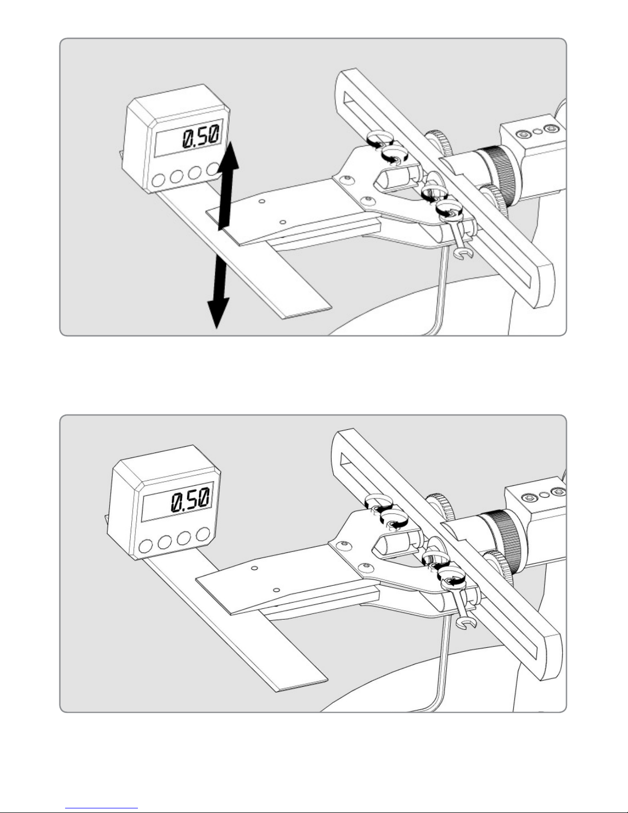
26
6. Place the digital gauge on the plate along the clamp’s rotation axis
and reset its value.
5. Thus, the jaws of the clamp should be parallel.

27
8. Make a measurement. The gauge will show the angles difference when
the clamp is fl ipped. If the deviation is <= 0.3° (or other value of required
accuracy), adjustment is not needed.
7. Flip the clamp over.
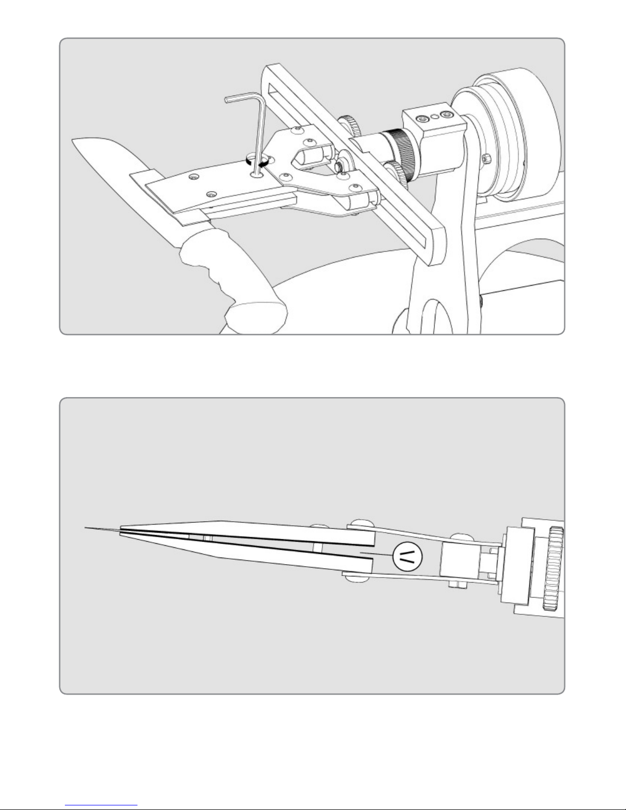
28
9. Loosen the screws to level this difference. Adjust the angle manually until
the gauge value is 1/2 of the difference measured before.
10. Holding this gauge value, tighten the screws.

29
11. Repeat the procedure in order to ensure an accurate setting.
1. Place the digital gauge on the sharpener’s base unit and reset its value.
Digital gauge platform horizontal calibration

30
2. Place the digital gauge on the digital gauge platform. If the deviation is <=
0.3° (or other value of required accuracy), adjustment is not needed.
3. Loosen the calibration screw with a 2mm hex key or torx t8, half-turn is
enough.
Next steps are needed to perform the calibration.

31
4. Holding the digital gauge platform with a hand from below and pressing it
up, adjust its angle according to the digital gauge value.
5. Keep holding the platform in the chosen position, remove the digital
gauge and tighten the calibration screw.

32
Digital gauge platform parallel calibration
1. Place a digital gauge onto the plate and reset its value.
2. Place a digital gauge on the digital gauge platform strictly as it’s shown in
the fi gure.
This calibration is performed after the Turning Clamp angle calibration.

33
3. Adjust the inclination of the platform to minimize the deviation. Use a 2mm
hex key or torx t8 to set its angle according to the digital gauge value.
The gauge will show the angle difference. If the deviation is <= 0.3° (or other
value of required accuracy), adjustment is not needed.
Next steps are needed to perform the calibration.

34
2. Stick a piece of leather or masking tape on the place of contact with the
jaws in order to avoid damage to polished or coated knives.
1. Loosen front and back holding screws.
Installation of a knife into the Single Clamp

35
3. Install a knife into the clamp.
4. Tighten the front holding screws slightly; fi nal tightening should be made
at the back screw.

36
1. Adjust the jaws position according to the length and geometry of the knife
blade and tighten the fi xing screws.
Installation of a knife into the Double Clamp
Loosen the tightening screws inversely to remove the knife.

37
1. Install a knife into the clamp.
Full fl at grind clamping
2. The rest clamping steps are the same as in the Single Clamp installation.

38
2. First - tighten the front holding screws slightly, then tighten the back one.
3. Loosen the front holding screws slightly.
39
4. Tighten the back screw a little bit more.
5. Thus, the jaws will settle at an angle to each other, as shown in the
fi gure.

40
Calibration of the in-built gauge
1. Install the digital gauge on the digital gauge platform. Arrange the device
as shown in the fi gure and reset it.
2. Install the digital gauge on the abrasive holder’s reference plate.

41
3. Loosen the screw at the back of the in-built gauge pointer.
4. Incline the bar until the digital gauge displays zero or a minimal value.

42
5. Holding the bar in this position, turn the pointer to the 0 mark on the angle
gauge.
6. Tighten the screw at the back of the pointer.

43
Adjustment of the sharpening angle
1. Install an abrasive and lean it against the cutting edge. Pay attention
that the abrasive thickness affects the sharpening angle.
2. Loosen the thumbscrew on the vertical angle bar to set the required
angle approximately by moving it up and down. Tighten the thumbscrew
back.

44
3. Loosen the lock-nut.
4. Turn the fi ne adjustment screw and set the exact sharpening angle.

45
Bar stoppers adjustment
1. The stoppers are adjusted after setting the sharpening angle. Loosen the
near stopper and position the near abrasive edge against the cutting edge
of a blade as it’s shown in the fi gures.
5. Tighten the lock-nut back.

46
1. Holding the abrasive in this position, move the stopper to the bush and
tighten its thumbscrew.

47
The procedure for the second stopper is the same.
48
1. When the abrasive is not in use, the bar can be parked. Turn the near bar
stopper’s thumbscrew downwards, as indicated in the fi gure.
Bar parking

49
2. Slide the bar against the stop and release it.

50
ТехноСтудия “Профиль”
426000, Россия, г. Ижевск
10 лет Октября 60, офис 405,
БЦ “Нова Парк”
Телефон: +7(3412)640-701, +7(3412)566-628
E-mail: info@tsprof.com
сайт производителя: tsprof.com
интернет магазин: shop.tsprof.com
Настоящая Инструкция по эксплуатации содержит сведения на
октябрь 2016 года.
 Loading...