

Page 1

Page 2
1
Introduction
TABLE OF CONTENTS
Page #
Contents ………..……………….……......…..2
Installation……………………………………...3
Operation………………………………..….....6
Updates…………………………………………..7
Troubleshooting………………………………8
TS Performance looks forward to serving the
technical needs you may run into, however, please
review all instructions outlined here and go over all
troubleshooting and updates before contacting TS
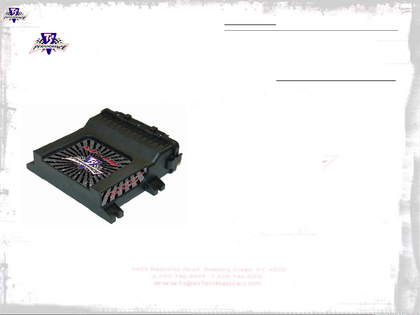
Performance at 270-746-9999. The Iveco power module
has been tested under the most harsh conditions
utilizing state of the art technology to deliver maximum
performance and reliability.
www.tsperformance.com
READ CAREFULLY BEFORE INSTALLING ANY TS PERFORMANCE PRODUCT
REMEMBER THIS IS A HIGH PERFORMANCE PRODUCT. USE AT YOUR OWN RISK.
FOR OFF ROAD USE ONLY.
Do not use this product until y ou have carefully read the following agreement. This
agreement sets forth the t erms and conditions for the use of the TS Performance product.
The installation of this product i ndi cates that the buyer has read and fully understands t hi s
agreement and accepts its terms and conditions.
DISCLAIMER OF LIABILITY
TS Performance, its distributors or dealers shall in no way be responsible for the product’s
proper use and service. The buyer of this system hereby waives all li abi l i t y clai ms.
buyer acknowledges that he i s not relying on the sellers ski l l or judgment to select or furnish
goods suitable for any partic ul ar purpose and that there are no liabilities which extend
beyond the description on the face hereof, and the buyer hereby waives all remedies or
liabilities, expressed or impl i ed arising by law or otherwise, (including without obli gations of
the seller with respect fitnes s, merchantability and consequential damages) or whether or
not occasioned by the seller’s negligence.
The seller disclaims any warranty and expressly disclaims any liability for personal injury or
damages. The buyer acknowledges and agrees that the disclaim er of any liability for
personal injury is a material term for this agreement and the buyer agrees t o i ndemnify the
seller and to hold the sell er harml ess from any claim related to the item of the equipment
purchased. Under no circumstances will the seller be liable for any damages or expenses
by reason of use or sales of any s uch equipment.
The seller assumes no liability regarding the improper installation or misapplication of its
products. It is the installer’s responsibility to check for proper installation and if in doubt the
manufacturer is to be contacted.
LIMITED LIFETIME WARRANTY
STATEMENT POLICY
The warranty policy is the best warranty within the high performance dies el indus t ry.
All TS Performance products have been i nspected, tested and trial in the factory
laboratories and on the fi el d.
Nothing in this Statement of Policy shall alter or enlarge the terms of warranties, obligation
or liabilities of these products.
TS Performance is not responsibl e or liable for any products dam aged or destroyed due to
improper installation.
TERMS OF WARRANTY
The defective product must be freight prepaid and returned to TS Performance for further
investigation, otherwise this warranty shall be deemed null and voided and of no effect.
This warranty is void on any products that show evidence of misapplication, negligence,
and improper installation, and abuse, lack of proper m ai ntenance or alternation from its
original design.
In no event will TS Performance be liable for any consequential or i ncidental damages for
breach of any express or impli ed warranty on the product.
This warranty is not transferable or assignable.
TS Performance is not responsibl e or liable for any products dam aged or destroyed due to
improper installation
.IN THE EVENT THAT TH E BU YER DOES NOT AGREE WITH THIS AGREEMENT: THE
BUYER MAY PROMPTLY RETURN THIS PRODUCT IN A NEW ANDN UNUSED
CONDITION WITH A DATED PROOF OF PURCHASE TO THE PLACE OF PURCHASE
WITHIN TEN (10) DAYS FROM DATE OF PURCHASE FOR A FULL REFUND.
The
11 2
Page 3
Troubleshooting
1. Be sure you have nice clean +12 Volt power to
Red wire with eyelet on fuel module
2. The Black wires on the module should be
routed to a good clean chassis ground.
3. Be sure that all the connectors on our harness
are connected to the truck and nothing is left
un-plugged. If so, this will cause an open loop
and will activate the check engine light.
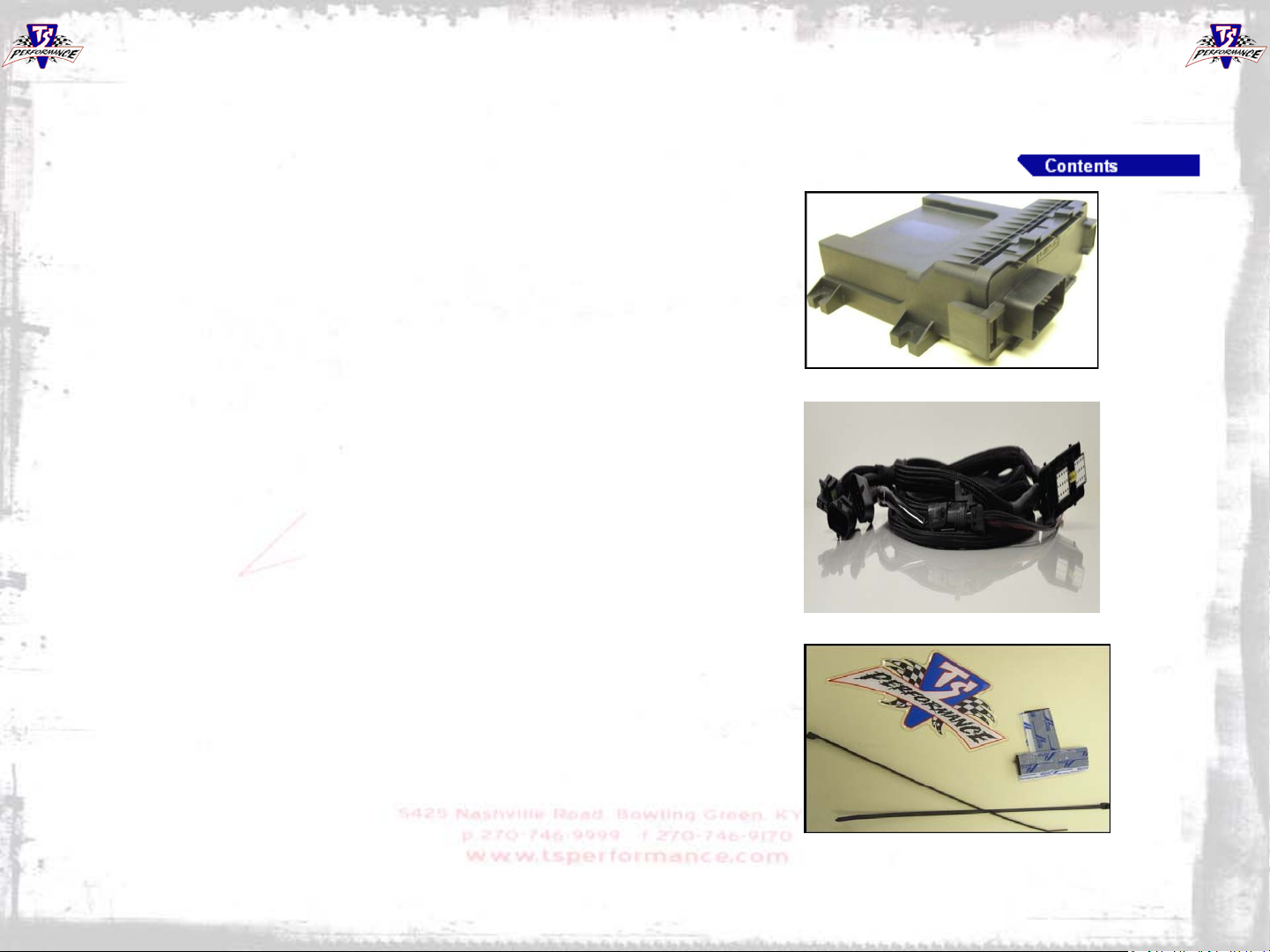
Contents of box
Module
10
Harness
zip ties, velcro
2
Page 4
Installation Overview
10.3L
UPDATE SECTION
With changes being made every year to engine parameters
and EPA restrictions, TS Performance has developed an
online Updater so your fuel module will never be out dated.
The Updater is located on our website. Utilizing the internet
allows your module to be updated with no CD’s or hardware
to be mailed back and forth. TS Performance fuel modules
are designed to change with an ever changing industry so
your vehicle will timeout before your TS Performance
purchase.
3
12.9L
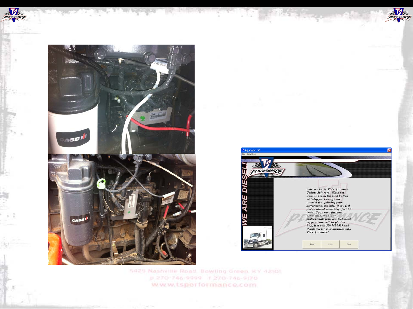
The ECM is located on the right side of the engine
compartment. The MPHD will connect to the injector
harness connector that plugs directly into the ECM and
adds fuel economy and horsepower by optimizing the
duration of fuel to each injector.
***Need help or more info??? Call: 270 -746-9999***
9
Page 5
Installation: Plug&Play
Harness Connection
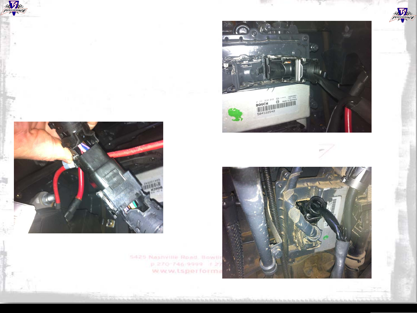
•Connect the factory harness that you disconnected from
the computer and connect it to the MPHD harness. Make
sure to line the tab on our connector up with the cut out on
the factory connector.
•The connector should latch and be secure when properly
installed.
Installation Overview
10.3L
On the 10.3L Engine the MPHD will plug into the
connector to the far right on the computer. Simply
disconnect the factory harness and connect our harness
as shown above..
8
On the 12.9L engine our MPHD will connect to the top
connector on the factory computer on the left side.
Simply disconnect the factory harness and connect our
harness as shown above
12.9L
4
Page 6
Installation: Module
Mounting location
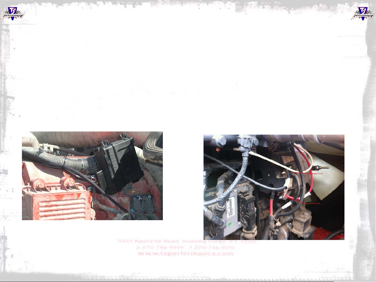
1. You can mount the MP-HD module anywhere away from
extreme environments. There’s plenty of room in the
harness to mount away from heat. We recommend
connecting it to a wire harness or other flat surface using the
supplied zip ties and/or velcro. Just be sure the module is
tightly secured to prevent damage.
Installation: Power and Ground
Power
1. Route the RED power wire from the module to a clean 12
Volts. On most applications the alternator is located close
by.
Ground
2. Route the BLACK ground wires from the module to clean
chassis ground or directly to battery, usually the alternator
on the passenger side of the vehicle is sufficient and easily
accessed.
6
7
 Loading...