

Page 1
TS PERFORMANCE
WE ARE DIESEL
TS Performance Products
MP-D
Thank you for buying the MPD for the Light Duty trucks. Here you will learn how
to install this MP-D into your truck, and we guarantee that you will be satisfied with
our product. Before you get started check to make sure that you have everything
below in the contents that came in the box
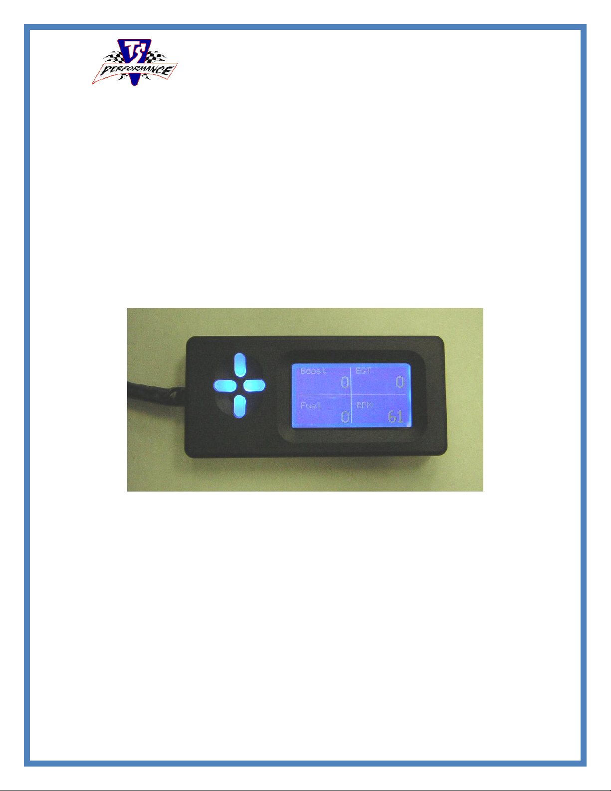
Monitor and Heads-up Display
Operation and Installation
Manual
Page 2
Continued
TSMPDw/MP-DHU
Operation of MP-D Monitor
Using the Monitor
1. Before driving the truck you will need go to the setup menu and select the proper vehicle file.
2. To access the set-up menu press the right button.
3. Then Choose select vehicle and select your application
4. Use the up and down buttons to scroll through the menu.
5. Use the right button to go to next menu and to select item
6. Use the left button to go back to the previous menu.
7. Once the vehicle has been selected you will need to set the “Disp. Brightness” and the “HU
Brightness”
8. Next you will need to set the “Alarms”. This is to be used to set the minimum or maximum in each
gauge that way an alarm will sound if you exceed the set amount.
9. Now set the Heads-Up Display how you want it by selecting “Invert HUD”. With it set as Heads-Up
mode it will shine onto the windshield. If you choose to invert the Heads-up it can be pointed toward
the driver.
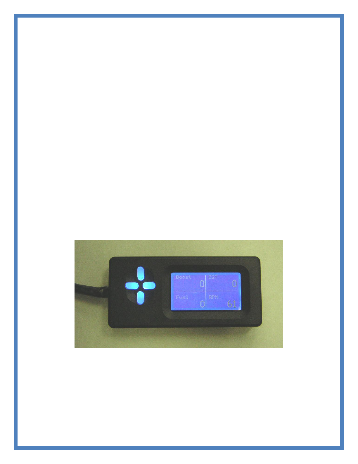
10. From Main menu shown below use the left button to see the min and max values logged form last time
started. If shut off will loose min and max values stored in monitor
11. From Main menu use the Up and Down button to scroll through the four readings to change what is
projected on the heads-up display
Harness Goes to Left as Shown
Page 3
Continued
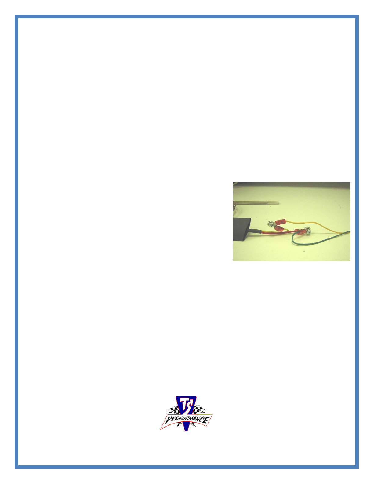
Figure 1: Pyrometer Hook up
Installation of TS Performance MP-D Monitor
Once you remove the monitor and Heads-Up Display from the box you will need to decide on a mounting
location. We suggest mounting the monitor in a location that can be reached from the driver’s seat or use
the optional windshield mount to mount display on the upper corner of the windshield. The Heads-Up
Display should be mounted on the dash pointed toward the windshield. Find a location that will not
obstruct the driver’s vision. We mount them in the left lower corner of the windshield. For best viewing
place the tint piece about an inch from the bottom of the windshield to reduce glair.
1. Separate the Red wire and the Black wire from the rest of the wire harness. These two wires will be
used for power and ground later.
2. Run the rest of the wires through the firewall. If you have gray wire it is not being used at this time so
cut it to get out of the way.
3. Be sure to route the wires away from heat and moving parts.
5. Connect the Red wire to a 12 volt power source with the key in the on position. This should not have
power going to it with the key in the off position.
6. Connect the Black wire to a constant ground.
7. Connect the wire harness to the Monitor and Heads-Up Display
and tie the wires up securely.
8. If you have and after-market exhaust fitted with a pyrometer
fitting you can insert the supplied probe into it. If not, you will
need to drill and tap the exhaust manifold on the driver’s side
from underneath. You will need to use an “R” or 11/37 drill bit
and a 1/8 NPT 27 tap. Make sure to use a small magnet to remove
the metal shavings before starting the truck.
9. Now connect the pyrometer wires to the Yellow and Green wires
coming from the harness. Connect Red-Green and YellowYellow using the supplied bolt and washer and heat shrink as
shown in the picture above.
10. The last step is to connect the wires for the boost, fuel
pressure, and tachometer.
11. Below look up the type of truck you are installing one to finish
install.
Note: Place a small amount of silicon RTV on the T-taps on all connections made under the
hood. This will insure that the connection is water tight and resist corrosion
Page 4
Continued
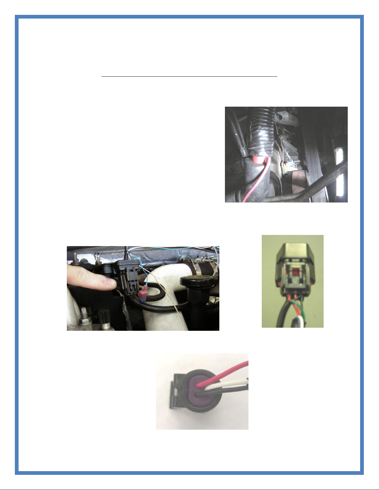
Figure 2: Cam Position Sensor
Figure 4: MAP Sensor
Figure 3:MAP Sensor
Connector
Figure 5: Middle wire across from
the clip (white wire in picture
above)
Application Specific Instructions:
Please skip to the application specific instructions for your application.
Ford 7.3L
1. Locate the Cam Position Sensor on the front of the engine
beside the CAM. It can be accessed from under the truck.
Route the white wire from the wiring harness to the CAM
Positions Sensor. Remove the loom going to the connector.
You will need to use the supplied T-tap to connect the white
wire from the harness to the bottom wire on the connector
(usually green).
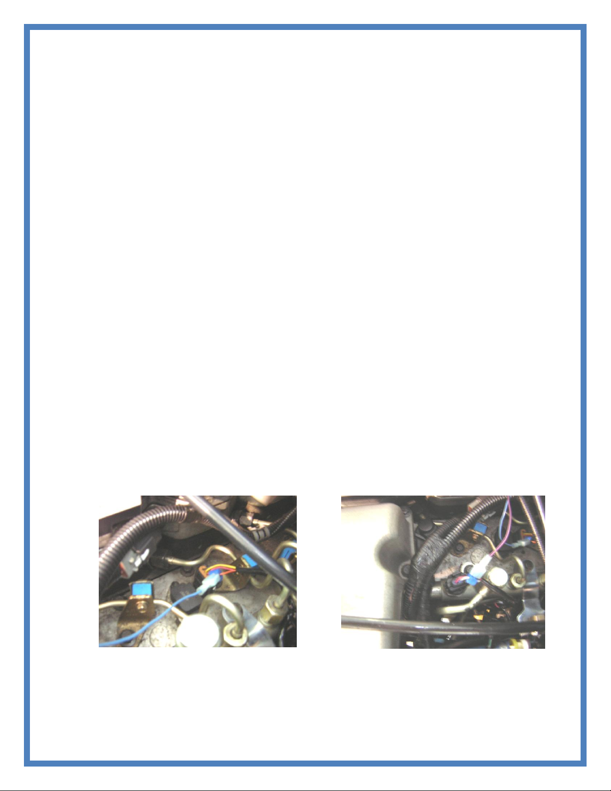
2. Locate the ICP Connector on the driver’s side valve cover.
Route the Purple wire in the wire harness to the ICP
connector. Using the supplied T-tap connects the purple wire
to the middle wire towards bottom on the ICP plug as shown
below.
3. Locate the MAP Sensor on the passenger’s side firewall.
Route the Blue wire from the wire harness to the MAP Sensor.
Using the supplied T-tap connects the blue wire to the middle
wire in the MAP Sensor Connector.
Page 5
Continued
Figure 7 : MAP Sensor Location
Figure 8 : Fuel Pressure Sensor Location
Ford 6.0
1. Locate the computer next to the battery on the driver side of the engine compartment. You will need to
remove the battery for better access to the computer.
2. Find the middle connector, remove the black plastic cover on the back of the connector. Locate the
dark blue wire in pin # 30. Using the 4 wire transformer provided, you will connect the blue wire from
the transformer provided to this wire using a t-tap. Connect the Yellow wire from the transformer to
the white wire on the harness going to the MPD. The Red wire will connect to a 12V power source
and the Black wire is a ground.
3. On the same middle connector as above. Locate the dark blue wire w/ green tracer in pin #29.
Connect the purple wire from the MPD harness to this wire using a t-tap.
4. Find the A connector on the computer. This connecter will be the larger of the two next to the middle
connector. Remove the black plastic cover on the back of the connector as you did before. Locate the
light green wire w/ black tracer in pin # 41. Connect the blue wire from the MPD to this wire using a
t-tap.
Dodge 03-07 5.9L
1. Locate the Crank Position Sensor on the front of the engine. It can be accessed from under the truck.
Route the White wire from our wire harness to the Crank Sensor. Using the supplied T-tap connects
the white wire to the Outside wire towards front of truck on the Crank Sensor connector.
2. Locate the Fuel Pressure Sensor on the driver’s side of the valve cover. Route the Purple wire to the
Fuel Sensor and using the supplied T-tap, connect it to the middle wire in the connector.
3. Locate the MAP Sensor on the driver’s side of the valve cover. Route the Blue wire to the MAP
Sensor and connect it using the supplied T-tap, connect to the outside wire TOWARD the driver side.
Page 6
Continued
Figure 9: Main Harness Connectors
Dodge 6.7L
1. Locate the Crank Position Sensor on the front of the engine. It can be accessed from under the truck.
Route the White wire from our wire harness to the Crank Sensor. Using the supplied T-tap connects
the white wire to the Outside wire towards front of truck on the Crank Sensor connector.
2. Locate the Fuel Pressure Sensor on the driver’s side of the engine. IT is the connector on the back of
the fuel rail with the three pin connector. Route the Purple wire to the Fuel Sensor and using the
supplied T-tap, connect it to the middle wire in the connector.
3. Locate the MAP Sensor on the intake air plenum on the driver’s side of the engine. The MAP sensor
is located on the back side of this plenum and will have a three pin connector. T-Tap the brown wire
farthest to the driver’s side of the connector.
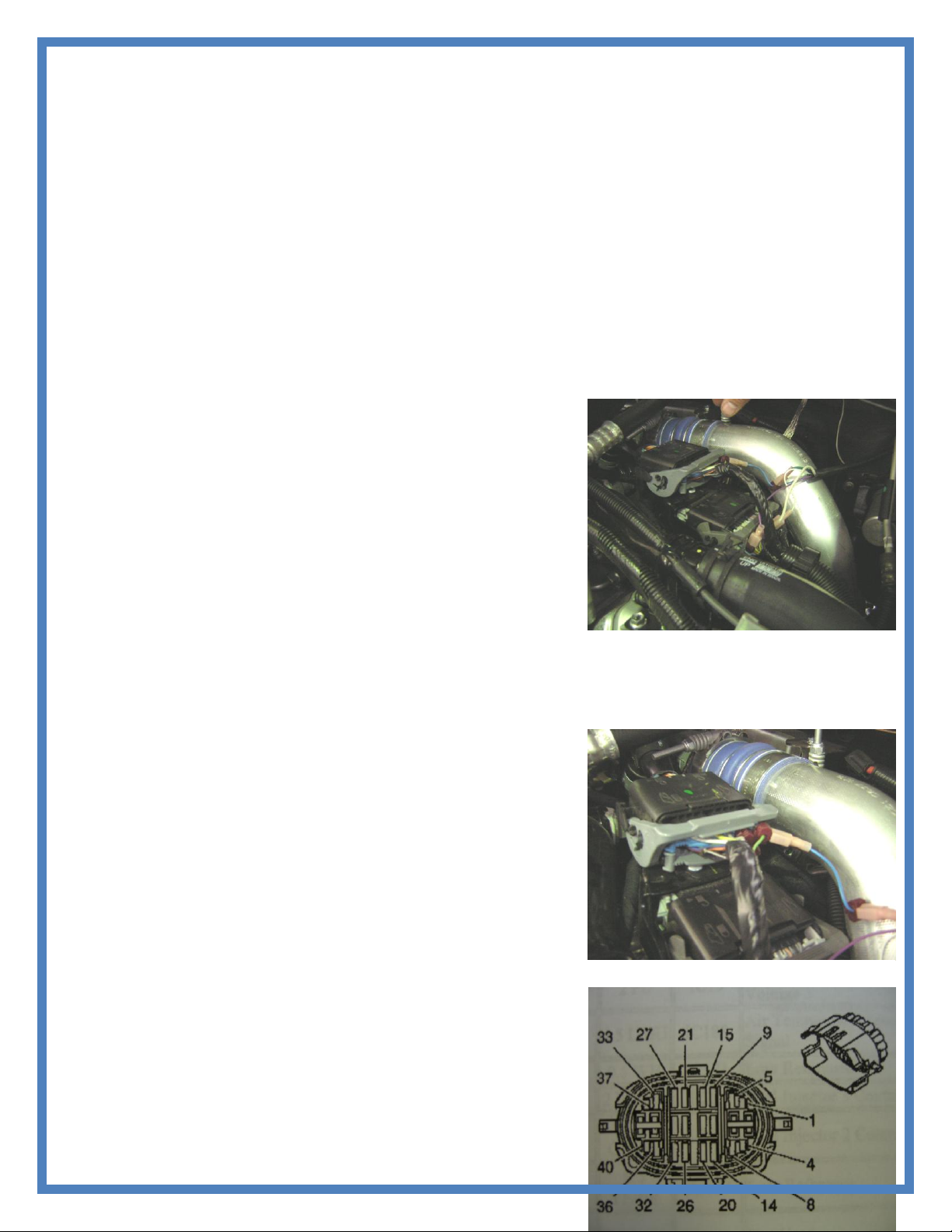
Duramax LB7, LLY, LBZ
1. Locate the Engine Harness Connector on the driver’s side of the
engine. This will be the larger of the two connectors. Route the
white wire from our wire harness to the connector. Use the
supplied T-tap to connect it to the blue wire with a white tracer.
It will be identified as B9 in the connector. The wires are
labeled A-D from the bottom to the top and 1-12 from the front
of the truck to the rear.
2. Locate the Fuel Pressure signal wire in the Engine Harness
Connector. Route the Purple wire to the Engine Harness
Connector. Connect it to the Yellow wire in location C5. The
wires are labeled like explained in step 6.
3. Locate the MAP Sensor signal wire in the Small Engine Harness Connector. This is located just above
the lager Engine Harness. Route the Blue wire to the harness and connect it to the Light Green wire in
location C8. The wires are labeled A-C from the bottom to the top and 1-12 from the front to the rear.
Duramax LMM
1. Locate the Fuel Rail Pressure Sensor in the lower Black Engine
Harness Connector. Using the Harness diagram supplied the
Fuel Rail Pressure., it is a yellow wire, located in Pin 23.
Connect the Purple wire from our harness to this pin using the Ttap Connector
2. Locate the MAP Sensor Connector in the same harness. It is a
light green wire, located in Pin 18 Connect the Blue wire from
our harness using the T-tap connector.
3. Locate the Tack wire in the same engine harness . It is a white
wire with a black tracer, located in Pin 17. Connect the White
wire from our harness using the T-tap connector.
If there are any questions on the product or installation of the module
give us a call at TS Performance (270) 746-9999
Page 7
Continued
851 Lovers Ln
Bowling Green, KY 42103
270-746-9999
TS Performance
www.tsperformance.com
DISCLAIMER
READ CAREFULLY BEFORE INSTALLING ANY TS PERFORMANCE PRODUCT
REMEMBER THIS IS A HIGH PERFORMANCE PRODUCT. USE AT YOUR OWN RISK. FOR OFF ROAD USE ONLY.
Do not use this product until you have carefully read the following agreement. This agreement sets forth the terms
and conditions for the use of the TS Performance product. The installation of this product indicates that the buyer has
read and fully understands this agreement and accepts its terms and conditions.
DISCLAIMER OF LIABILITY
TS Performance, its distributors or dealers shall in no way be responsible for the product’s proper use and service. The
buyer of this system hereby waives all liability claims. The buyer acknowledges that he is not relying on the sellers
skill or judgment to select or furnish goods suitable for any particular purpose and that there are no liabilities which
extend beyond the description on the face hereof, and the buyer hereby waives all remedies or liabilities, expressed or
implied arising by law or otherwise, (including without obligations of the seller with respect fitness, merchantability
and consequential damages) or whether or not occasioned by the seller’s negligence.
The seller disclaims any warranty and expressly disclaims any liability for personal injury or damages. The buyer
acknowledges and agrees that the disclaimer of any liability for personal injury is a material term for this agreement
and the buyer agrees to indemnify the seller and to hold the seller harmless from any claim related to the item of the
equipment purchased. Under no circumstances will the seller be liable for any damages or expenses by reason of use or
sales of any such equipment.
The seller assumes no liability regarding the improper installation or misapplication of its products. It is the installer’s
responsibility to check for proper installation and if in doubt the manufacturer is to be contacted.
LIMITED LIFETIME WARRANTY
STATEMENT POLICY
The warranty policy is the best warranty within the high performance diesel industry.
All TS Performance products have been inspected, tested and trial in the factory laboratories and on the
field.
Nothing in this Statement of Policy shall alter or enlarge the terms of warranties, obligation or liabilities of
these products.
TS Performance is not responsible or liable for any products damaged or destroyed due to improper
installation.
TERMS OF WARRANTY
The defective product must be freight prepaid and returned to TS Performance for further investigation,
otherwise this warranty shall be deemed null and voided and of no effect.
This warranty is void on any products that show evidence of misapplication, negligence, improper
installation, and abuse, lack of proper maintenance or alternation from its original design.
In no event will TS Performance be liable for any consequential or incidental damages for breech of any
express or implied warranty on the product.
This warranty is not transferable or assignable.
TS Performance is not responsible or liable for any products damaged or destroyed due to improper
installation.
IN THE EVENT THAT THE BUYER DOES NOT AGREE WITH THIS AGREEMENT: THE BUYER MAY PROMPTLY
RETURN THIS PRODUCT IN A NEW ANDN UNUSED CONDITION WITH A DATED PROOF OF PURCHASE TO THE
PLACE OF PURCHASE WITHIN TEN (10) DAYS FROM DATE OF PURCHASE FOR A FULL REFUND.
THE INSTALLATION OF THIS PRODUCT INDICATES THAT THE BUYER HAS READ AND UNDERSTATNDNS
THIS AGREEMENT AND ACCEPTST ITS TERMS AND CONDITITONS.
Page 8

Continued
WWW.TSPERFORMANCE.COM
FOR TECHNICAL SUPPORT
(270) 746-9999
 Loading...