

Page 1
TS PERFORMANCE
Contents:
(1) Switch
(2) Butt
Connectors
(2) T-taps
(2) Zip ties
(1) Eyelet
Connector
(1) 12” black
wire
(2) Blue, (1)
Pink Connector
WE ARE DIESEL
TS Performance Products
Re-Speed
Tire Calibration and Speed Limiter
Removal Operation & Installation Manual
Installation of the TS Performance Re-Speed
Read all instructions and fully understand them before installing your TS Performance Re-Speed
module. Disconnect the battery terminals and remove keys from ignition before installation.
Page 2
Continued
Installation:
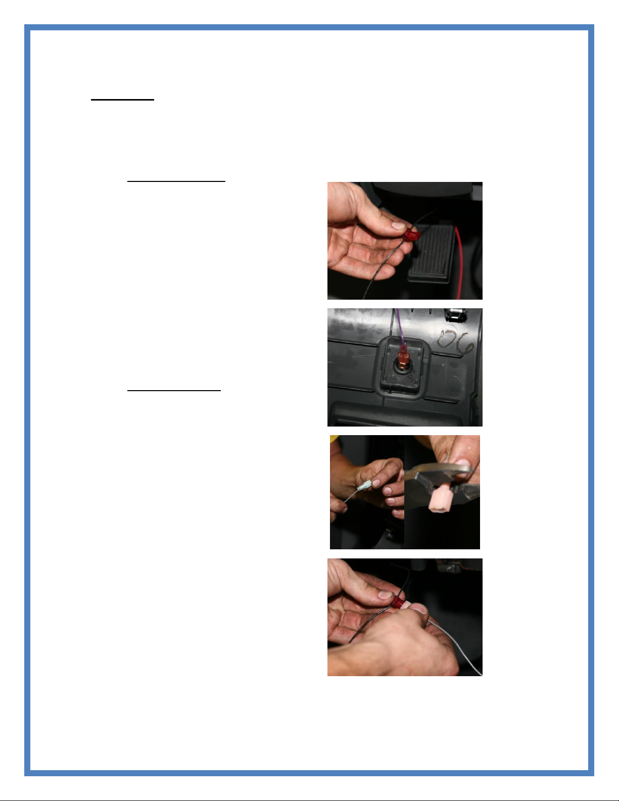
1) Use supplied pink connector, crimp to RED wire on ReSpeed; crimp supplied eyelet to BLACK
wire.
2) Use the supplied T-tap and tap RED wire into KEY ON +12 V usually located under the dash.
3) Connect the black wire to good clean ground.
4) Put the other T-tap on black wire to add speed limiter switch later (Figure 1).
Speed Sensor Hook-up
5) The speed signal wires are usually
twisted together and sometimes
wrapped in black tape unless coming
from the ABS or PCM. One of these
wires is sensor ground and the other
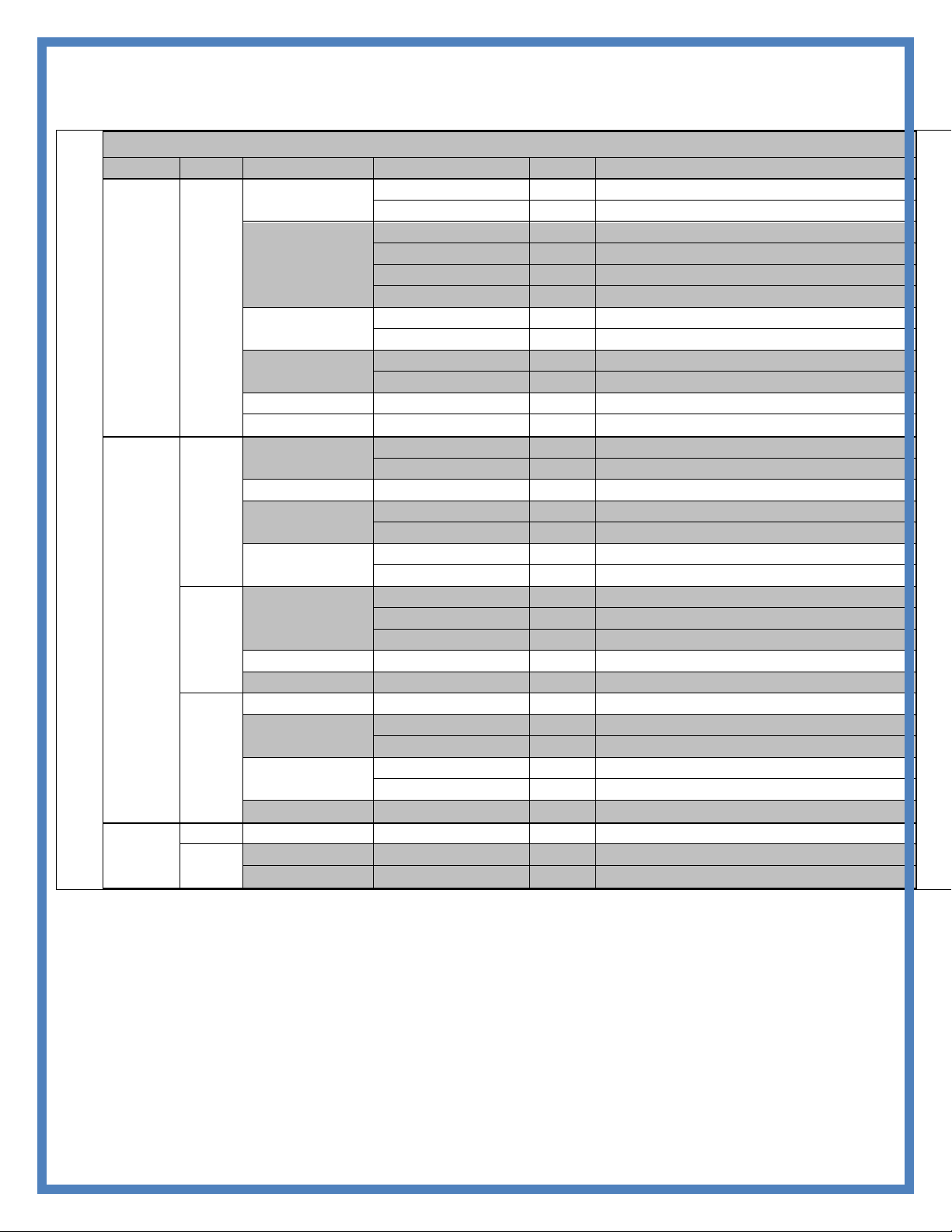
carries the signal. Refer to Chart D to
locate you speed signal wire. Cut the
speed signal wire.
6) Using supplied blue butt connectors,
connect the Respeeds Green wire to the
cut wire coming from sensor. The
green wire is the Respeed input and the
white wire is the output.
7) Connect the Respeeds white wire to the
wire going to PCM also using the
supplied blue butt connectors.
Speed Limiter Switch
The speed limiter switch turns the speed limiter
on the vehicle on or off. Pushing the switch
allows the ReSpeed module to see ground and
disable the speed limiter.
a. Mount the switch in an
accessible area (Figure 2).
b. Connect purple wire from
Respeed to one side of the
switch using a blue connector.
c. Connect supplied wire to the
other side of switch using a
blue connector. Then run the
other side of supplied wire to
ground using pink connector
(Figure 4).
d. Connect the pink connector to
the red T-tap applied to ground
wire earlier in instructions.
(Figure 4).
Figure 2
Figure 1
Figure 3
Figure 4
Page 3
Continued
Disable speed limiter
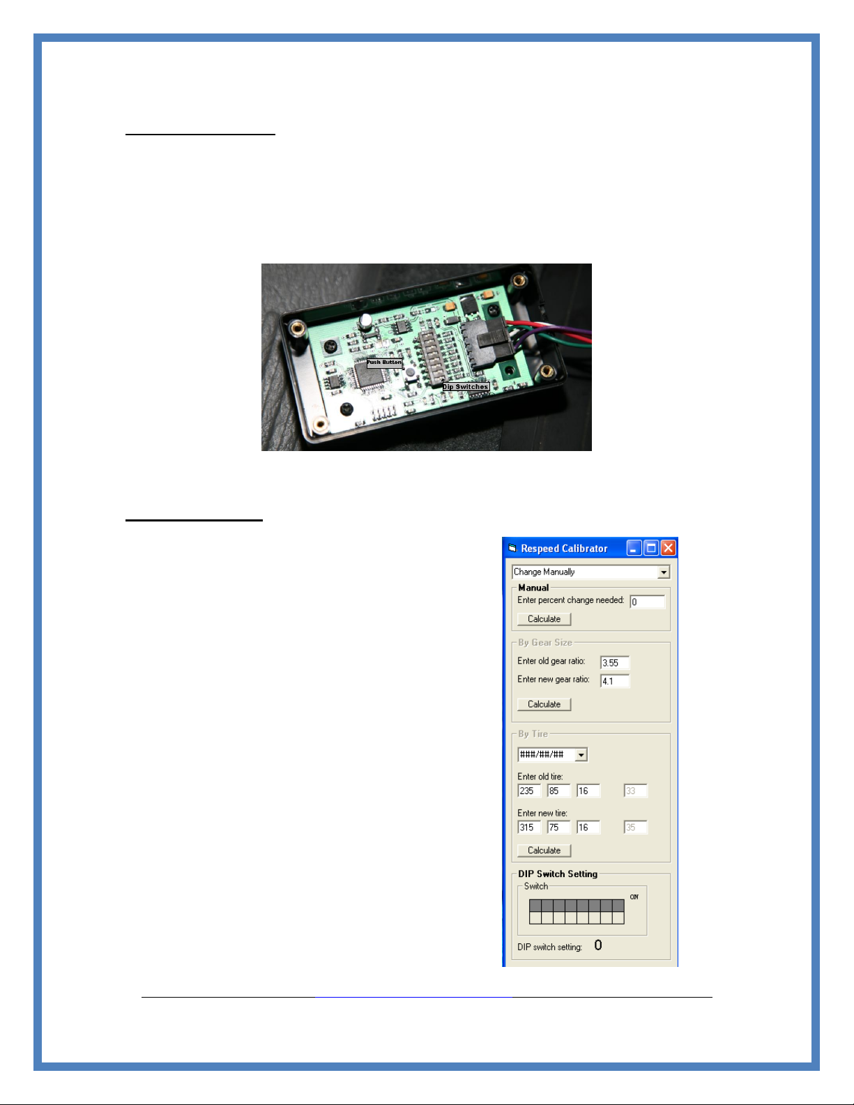
1) Leave key off and locate the push button next to the dip switches on re-speed board (Figure 5).
This button allows the re-speed to go into SET mode if pushed while powering up.
2) Hold the button down and turn the vehicle on then release the button.
3) The re-speed is now in SET mode. Get the vehicle to the maximum speed desired and push the
button again. Now the maximum speed is stored. This lets the computer only to see the
maximum speed; disabling the speed limiter. Turn the external switch to ON position. The speed
limiter is now disabled and the tachometer should never go above maximum desired speed.
Tire Calibration
1) Locate the 8 pin dip switch on the re-
speed shown (Figure 6). Each dip
switch combination will adjust the
speed by a percentage.
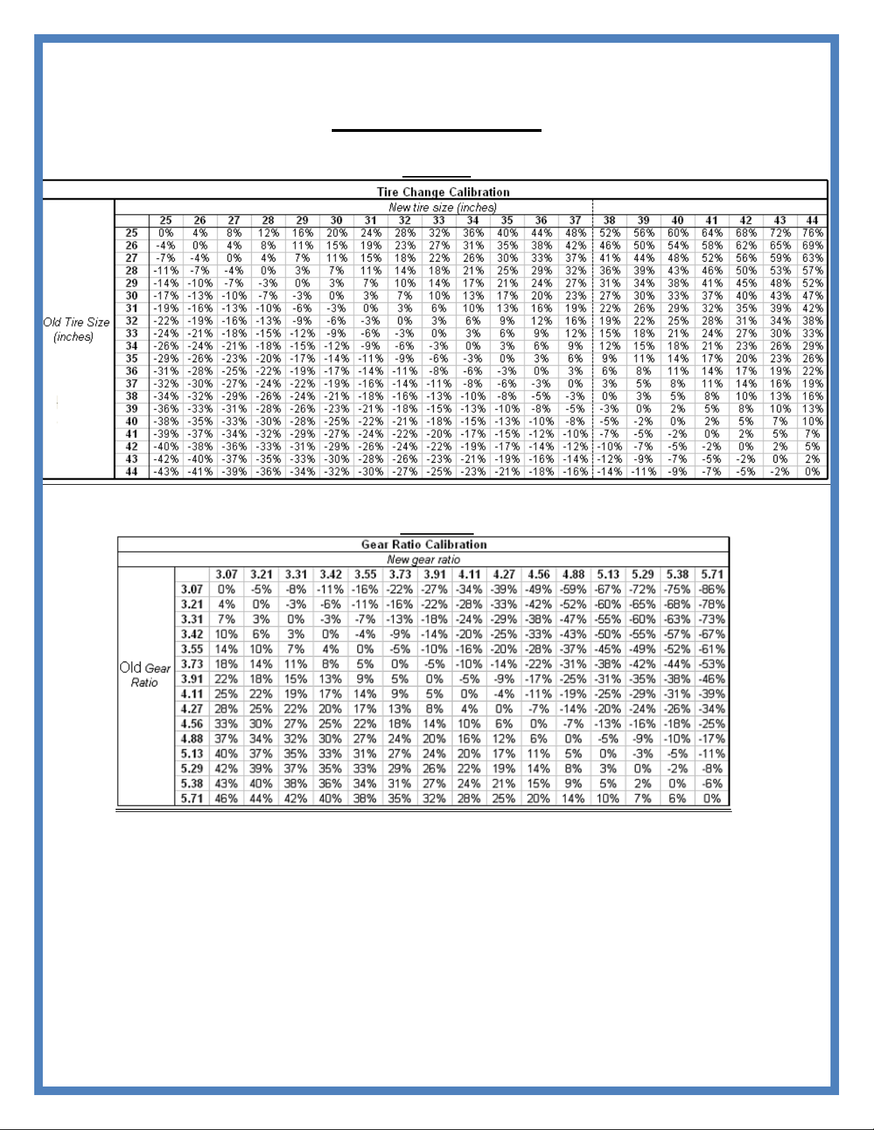
2) To obtain the percent changes in speed
refer to the Calibration Chart A on the
following page.
3) Find your old tire diameter on the left
column. From there go over to the new
tire diameter, the cell you come to
refers to your percent change in tire
size.
4) Next refer to the Dip Switch Chart C
on the following page, look at the
percent change to find the dip switch
settings for the right speed
compensation.
5) The same method is used for a change
in gears. Just refer to the Gear Ratio
Chart B.
6) If the vehicle has new tires and gears,
find the percent change from both
charts and add them together.
Figure 5
See our ReSpeed Calculator at WWW.TSPERFORMANCE.COM to easily obtain dip switch settings.
Page 4
Continued
Calibration Charts
Tire Ratios
Chart A
Gear Ratios
Chart B
Dip Switch Chart
Page 5
Continued
%Change in Speed
Dip Switch Values
%Change in Speed
Dip Switch Value
30%
11001100
0%
11111111
29%
10101100
-1%
00111111
28%
00011100
-2%
01011111
27%
01011100
-3%
11101111
26%
10111100
-4%
00101111
25%
11111100
-5%
10001111
24%
01000010
-6%
01110111
23%
00100010
-7%
11010111
22%
11100010
-8%
00010111
21%
10010010
-9%
10100111
20%
00110010
-10%
01000111
19%
11110010
-11%
11111011
18%
10001010
-12%
11011011
17%
00101010
-13%
00011011
16%
01101010
-14%
10101011
15%
10011010
-15%
10001011
14%
11011010
-16%
01110011
13%
01111010
-17%
01010011
12%
00000110
-18%
01100011
11%
11000110
-19%
01000011
10%
01100110
-20%
01111101
9%
00010110
-21%
01011101
8%
01010110
-22%
01101101
7%
11010110
-23%
10001101
6%
00001110
-24%
10110101
5%
01001110
-25%
00010101
4%
10101110
-26%
00100101
3%
00011110
-27%
11111001
2%
01011110
-28%
01011001
1%
00111110
-29%
10101001
0%
11111111
-30%
00001001
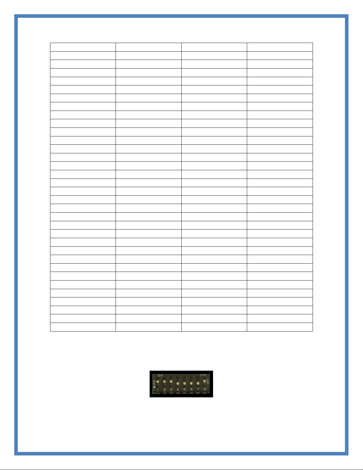
*** 1 represents dip switch on, 0 represents dip switch off, for example the dip switch
settings in Figure 6 is the equivalent of 11100001.
Chart C
1 1 1 0 0 0 0 1
Figure 6
Page 6
Continued
TS Performance Re-Speed Guide
Part #
Make
Model
Tears
Sensor
Wire Color, Location
1190101
Ford
F-150
1992-1996
VSS
Red/Pink, behind speedometer
1997-1998
VSS
Grey/ Blk, behind speedometer
F-250
1992-1996
VSS
Red/Pink, behind speedometer
1997 HD
VSS
Red/Pink, behind speedometer
1997-1998 LD
VSS
Grey/BLK, behind speedometer
1999-2006
ABS
Grey/Blk, from ABS
F-350
1992-1997
VSS
Red/Pink, behind speedometer
1999-2006
ABS
Grey/Blk, from ABS
Bronco
1992-1996 2W ABS
VSS
Red/Pink, behind speedometer
1994-1996 4W ABS
ABS
Org/Lt.Blue, from ABS (pin 39)
Explorer
1995-1997
OSS
Grey/Blk, from Transfer case
Mountainer
1995-1997
OSS
Grey/Blk, from Transfer case
1190102
Ford
Explorer
1998-2001
ABS
Grey/Blk from ABS (pin 19)
2002-2003
PCM
Grey/Blk at PCM (pin 68)
Mountainer
1998-2002
ABS
Grey/Blk from ABS (pin 19)
Sport Trac
1999-2001
ABS
Grey/Blk, from ABS (pin 19)
2002-2003
PCM
Grey/Blk, at PCM (pin 68)
Ranger
1998-2000
ABS
Grey/Blk, from ABS (pin 10)
2001-2002
GEM
Grey/Blk, at GEM Module C201B (pin 14)
Dodge
Ram
1992-1997
OSS
White/Orange, from Transfer case
1998-2002
ABS
White Orange, from ABS
2003-2005
ABS
Grey/Blk behind battery from ABS
Dakota
1992-1997
OSS
White/Orange, from Transfer case
Dakota/Durango
1998-2003
ABS
White/Orange, from ABS
Jeep
Cherokee
1992-2001
OSS
White/Orange, from transfer case
Grand
Cherokee
1994-1998
OSS
White/Orange, from Transfer case
1999-2001
ABS
White/Orange, from ABS (pin 3)
Wrangler
1992
OSS
Blue, from Transfer case
1993-2003
OSS
White/Orange, from Transfer case
Liberty
2002-2003
ABS
Dk Grn/Orange, from ABS
1190103
Ford
F-250
2007-2008
VSS
Tan/Grn, from back differential
Dodge
Ram
2006
VSS
Red/Pink, back Differential
Ram
2007
VSS
Green/Yellow, back Differential
Chart D
Page 7

Continued
TS Performance
851 Lovers Ln
Bowling Green, KY 42103
270-746-9999
www.tsperformance.com
DISCLAIMER
READ CAREFULLY BEFORE INSTALLING ANY TS PERFORMANCE PRODUCT
REMEMBER THIS IS A HIGH PERFORMANCE PRODUCT. USE AT YOUR OWN RISK. FOR OFF ROAD USE ONLY.
Do not use this product until you have carefully read the following agreement. This agreement sets forth the terms
and conditions for the use of the TS Performance product. The installation of this product indicates that the buyer has
read and fully understands this agreement and accepts its terms and conditions.
DISCLAIMER OF LIABILITY
TS Performance, its distributors or dealers shall in no way be responsible for the product’s proper use and service. The
buyer of this system hereby waives all liability claims. The buyer acknowledges that he is not relying on the sellers
skill or judgment to select or furnish goods suitable for any particular purpose and that there are no liabilities which
extend beyond the description on the face hereof, and the buyer hereby waives all remedies or liabilities, expressed or
implied arising by law or otherwise, (including without obligations of the seller with respect fitness, merchantability
and consequential damages) or whether or not occasioned by the seller’s negligence.
The seller disclaims any warranty and expressly disclaims any liability for personal injury or damages. The buyer
acknowledges and agrees that the disclaimer of any liability for personal injury is a material term for this agreement
and the buyer agrees to indemnify the seller and to hold the seller harmless from any claim related to the item of the
equipment purchased. Under no circumstances will the seller be liable for any damages or expenses by reason of use or
sales of any such equipment.
The seller assumes no liability regarding the improper installation or misapplication of its products. It is the installer’s
responsibility to check for proper installation and if in doubt the manufacturer is to be contacted.
LIMITED LIFETIME WARRANTY
STATEMENT POLICY
The warranty policy is the best warranty within the high performance diesel industry.
All TS Performance products have been inspected, tested and trial in the factory laboratories and on the
field.
Nothing in this Statement of Policy shall alter or enlarge the terms of warranties, obligation or liabilities of
these products.
TS Performance is not responsible or liable for any products damaged or destroyed due to improper
installation.
TERMS OF WARRANTY
The defective product must be freight prepaid and returned to TS Performance for further investigation,
otherwise this warranty shall be deemed null and voided and of no effect.
This warranty is void on any products that show evidence of misapplication, negligence, improper
installation, and abuse, lack of proper maintenance or alternation from its original design.
In no event will TS Performance be liable for any consequential or incidental damages for breech of any
express or implied warranty on the product.
This warranty is not transferable or assignable.
TS Performance is not responsible or liable for any products damaged or destroyed due to improper
installation.
IN THE EVENT THAT THE BUYER DOES NOT AGREE WITH THIS AGREEMENT: THE BUYER MAY PROMPTLY
RETURN THIS PRODUCT IN A NEW ANDN UNUSED CONDITION WITH A DATED PROOF OF PURCHASE TO THE
PLACE OF PURCHASE WITHIN TEN (10) DAYS FROM DATE OF PURCHASE FOR A FULL REFUND.
THE INSTALLATION OF THIS PRODUCT INDICATES THAT THE BUYER HAS READ AND UNDERSTATNDNS
THIS AGREEMENT AND ACCEPTST ITS TERMS AND CONDITITONS.
Page 8

Continued
WWW.TSPERFORMANCE.COM
FOR TECHNICAL SUPPORT
(270) 746-9999
 Loading...