

Page 1
T3-1
series
Ultrasonic Water Meter
Installation Instruction
Welcome use the T3-1 series ultrasonic water meter
The water meter be adapted by the advanced ultrasonic transit-time measurement technology
according to GB/T778.1-2007, IOS4064-1:2005 standard
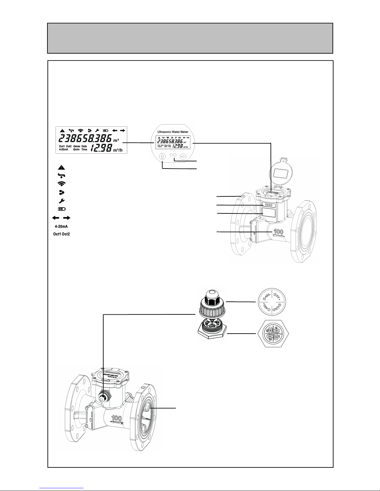
1. Parts Description
Front View
Display:
Alarm/Error
Leak Detector
Wireless Power Supply
Communication
Permanent Fault
Battery Low Warning
Liquid Direction
Current Loop Connection
Pulse Output
Stable Flow Device
Standard:
1 485+(A)
2 485 -(B)
3 DC8-36V
4 GND
Provide below communication interface and output
1. RS485
2. M-BUS
3. DC8-36V
4. Two-wired system 4-20mA output
5. OCT1(open collector output 1)
6. OCT2( open collector output2)
7. C1(TTL level pulse output 1)
8. C2(TTL level pulse output 2)
Touch Key
Infrared Communication Interface
Ground Terminal
Batch Number
Label
Pipe Diameter and
Fluid Arrow Direction
Junction
Box Cover
Junction
Terminal
External Waterproof Junction Box
Can complete the wiring junction
without opening the water meter cover
PS:when ordering, you can choose any two of the above communication
interface or output, lead to the external junction box
Back View
Page 2
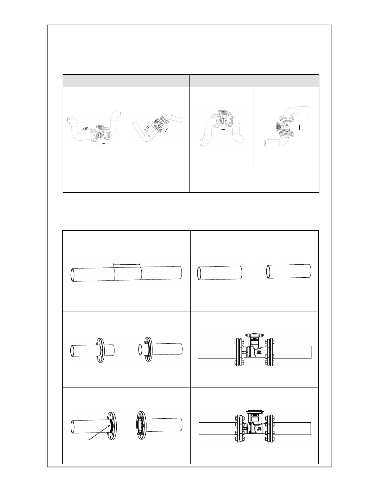
2. Installation Instruction
2.1 Choose the installation point
Straight pipe installation requirement(D is pipe diameter), upstream ≥ 3D, downstream 0D,
make sure the pipe full of liquid completely.
Correct installatio n point Wrong installation point
At the lowest point in the pipe system;
Vertical upward or slanted upward pipe;
Upstream straight pipe≥3D
At the highest point in the pipe system;
Vertical downward or slanted downward
pipe; Upstream straight pipe<3D
ps: Arrow direction is fluid flow direction.
2.2 Installation Method
1.Confirm installation dimension
2.Cup off
Water meter length L+2pcs sealing gasket thickness+10mm
3.Install matching flanges
4.Flanges position
5.Flanges welding
6.After cooling, install with sealing gasket,
fasten screws
Three screws on an average positioning flanges,
spot-welding fixing
Take off the wate r mete r,
finish ful l weld ing of the fl an ge
Page 3

3. Calibration Method
There are two kinds of calibration met hod of T3 water meter, including the start-stop method and constant-current method
3.1 Start-Stop Method
Start-stop method be defined in the stationary states, start and stop the calibration device(standard water meter) and tested
water meter simultaneously, is a calibration method by the measured accumulative flow
Please go to Menu 05, you are no need to operate the keypad during the calibration process. When the static fluid is more than
20 seconds, the left side of the window will display “1”; Then open the valve, “P” will be flashing, means during the calibration process,
calibration accumulator to Zero and begin to count immediately. W hen meet the requirement of accumulative flow value, close the
valve, flow will be reduced gradually until the “P” without flashing, it will display “1” when the fluid in stationary states. Finish the above
process, you can read out the calibrate value from the accumulator, divide water volume of the standard container, that is the relative
error. For the start-stop method, the start duration should be more than 60 seconds each time. The shorter duration, the more relative
error caused.
3.2 Constant-Current Method
Constant-current method be defined at the set of flow point, make the calibrat ion device(standard water meter) and tested water
meter into stable flow state, is a calibrat ion method by the measured accumulative flow at the same time.
Please go to Menu 05, press “
“ into constant-current window. the lest side of the window display capital letter “C”.
Constant-current method is no need the static flow. When flow stable, press “
“, calibration accumulator begin to count, lowercase
letter “c” will be flashing, when require to stop, press “
“ again.
In the calibration window, second line on the display is average instantaneous flow rate of the calibration period time, rather than
the instantaneous flow rate instantly. Its formular is : average instantaneous flow rate= accumulative flow rate of calibration period
time ÷ calibration period time.In the constant-current window, press “
“, means exiting and entering into start-stop method window
According to the simulate keypad operation, also can achieve the constant-current method calibrat ion by RS485 or infrared
interface. Calibrate accumulator valve and calibrate accumulator operation time can be read out by computer and calculate the
relative error automatically, there is the correction factor, which will download to the water meter automatically to realize calibration
process automation.
3.3 Flow Range
Nominal
Diameter
( mm)
R
Flow (m³/h)
Starting
Flow rate
Minimum
Flow ra te
Q1
Transit ional
Flow rate
Q2
Perman ent
Flow rate
Q3
Overload
Flow ra te
Q4
DN15 200 0.003 0.0125 0.020 2.500 3.125
DN20 200 0.0035 0.016 0.030 3.200 4.000
DN25 200 0.007 0.020 0.030 4.000 5.0 00
DN32 200 0.010 0.032 0.0504 6.300 7.875
DN40 200 0.015 0.100 0.160 20.000 25.000
DN50 100 0.030 0.400 0.640 40.000 50.000
DN65 100 0.059 0.630 1.008 63.000 78.750
DN80 100 0.064 1.000 1.600 100.0 00 125.000
DN100 100 0.094 1.600 2.560 160.000 200.000
DN125 100 0.120 2.000 3.200 200.000 250.000
DN150 100 0.270 2.500 4.000 250.000 312.500
DN200 100 0.315 4.000 6.400 400.000 500.000
DN250 100 0.508 4.000 6.400 400.000 500.000
DN300 100 0.770 6.300 10.08 0 630.000 787.500
Page 4

4. Menu Introduction
4.1Operation Method
T3-1 series ultrasonic water meter is touch keyboard operation, there are two buttons”
” and ””.
Keyboard mnemonic: left click”
” is up; right click”” is down; left-right click”
” is modification ; right-left
click”
” is exiting
4.2 Menu Windows
Menu
Windows
No. Windows description and functions
Main Menu
M00
Wat er met er : Display Net cumul ative flo ws and ins ta ntane ou s flows
Heat meter :D ispla y PO S (positi ve )cu mu lat iv e heat s and inst ant an eo u s he at s
M01
Displa y POS cu mu lat ive flows and instant an eou s flow s
(water met er wit hout th is Men u)
M02
Displa y the su pply an d re tur n wa ter tempera ture an d te mpera ture di ff erenc e( water met er
withou t th is Me nu , unit is on ly ℃ )
M03
Cale nd ar, fi rs t li ne di sp lay date an d week ; Se con d li ne disp la y the hour and min ut e
M04
Firs t li ne di sp lay tw o w ay si gnal st ren gt h,fai lu re err or co de; Se co nd li ne di sp lay tw o way
sign al qua li ty
M05 Calibration menu
M06 Batch controller (irrigation controller)
T3-1series ultrasonic water meter include 5 kinds of menus: main menu, secondary menu1, secondary menu2, batch control
menu and time-accumulated menu. Under the main menu, you can enter into any menu by the modification key”
”.
Example:
M00, press “
” enter into the month cumulative flow;
M03, press “
” enter into secondary menu1 (M10~M19);
Under the M19 of the secondary men1, press “
” enter into secondary menu2 (M20~M2A);
M04, press “
” enter into date cumulative flow;
M05, start-stop method calibration state; press “
” enter into constant-current method calibration state;
M06, press “
” enter into batch control and time-accumulated menu(M30~M3C);
5. Others
More detailed information of T3-1 series ultrasonic water meter, please refer to the << T3-1 series ultrasonic water meter user
manual>>
Including:
Windows description
How to modify the unit of measure?
How to modify the decimal point location of the cumulative flow?
How to reset the time?
How to check whether the water meter work well completely?
How to use the built-in batch controller?
How to modify the communication address?
How to modify the time point of the time-accumulator?
How to modify the infrared communication rates?
How to modify the RS485/M-bus communication rates?
……
 Loading...