

Page 1
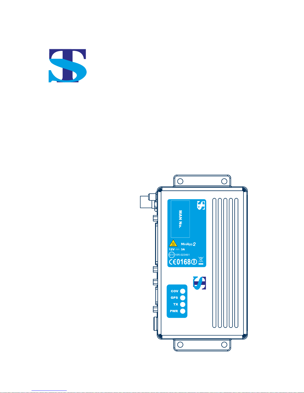
TS Mobile
TS - D400
TS - D400gps
User Guide
TS Mobile
TS-D400 GPS : 10W Mobitex
Freq : 405 ~ 465 MHz
Made in Republic of Korea
TS Mobile
Page 2

Contents
Introduction ..............................................................................................2
Preparing for use .....................................................................................3
Description of modem ........................................................................3
MAN Numbers and MSN Number .....................................................3
Installation ...............................................................................................4
Antennas............................................................................................4
Power sources ...................................................................................4
Fusing ................................................................................................4
Fuse replacement ...........................................................................4
Cabling...............................................................................................5
Fixing .................................................................................................5
Connections.............................................................................................6
Start up & shut down ...............................................................................7
Introduction ........................................................................................7
Start up routine ..................................................................................7
Shut down routine ..............................................................................7
Safety and general information................................................................8
Warranty and repairs ...............................................................................9
Care of the equipment .............................................................................9
Disposal / Recycling ................................................................................9
Declaration of conformity .......................................................................10
Relevant specifi cations ....................................................................10
1
Page 3

Introduction
The TS-D400 range is a 10 Watt Wide-band (405 to 465MHz) radio data modem for
use on the 8kB/s Mobitex Networks.
The TS-D400 offers, as standard, a serial data interface conforming to MASC
standard together with PacketAT, which simplifi es communication, and a telemetry
interface which provides up to 12 confi gurable data lines.
The TS-D400 is housed in a rugged cast-aluminium box sealed to IEC 529 (IP54)
making it suitable for a wide range of mobile and fi xed applications.
All TS-D400 modem units meet the essential requirements of the relevant European
directives. In order to maintain this compliance the installation and safety information
must be adhered to at all times.
The TS-D400 modem must only be installed where unintentional contact
cannot be made. The surface of the device may be hot to touch under certain
transmit conditions. A warning label is permanently displayed as part of the
equipment rating label affi xed to the lid. The TS-D400 is not designed for per-
manent transmission, it is a packet data system. When used for packet data,
the TS-D400 will operate just slightly warm under most conditions.
When fi tting the modem into a fi xed installation, such as a vehicle for exam-
ple, care must be taken in the routing of all cabling such that the insulation
cannot become damaged.
The inline “quick blow” fuse rating of 4 amps must not be exceeded at any
time. See Fusing (under Installation) for further instructions
The recommended supply sources for use with the TS-D400 are a standard
12 volt vehicle battery but is capable of operating in the range (10.8V ~
15.6V).
●
●
●
●
2
Page 4
Preparing for use
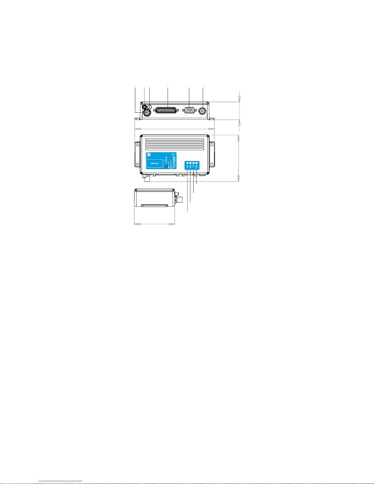
Description of modem
1 Power input (2 pin or 4 pin including ignition line depending on the
model number)
2 RS232 control port (MASC, PacketAT): 9-way d-type
3 Telemetry/Serial TTL port (Masc, Debug, GPS): 25 way d-type
4 Aux
5 GPS antenna connector: SMA, if fi tted
6 Mobitex antenna connector: TNC
7 LED’s:
A) Orange – Mobitex coverage
B) Yellow – GPS coverage
C) Green – Transmitting / programming indicator
D) Red – power (power to unit and switched on)
The modem can be attached to any surface by using suitable size screws through
the 5 mm holes in the mounting fl anges.
MAN Numbers and MSN Number
The Mobitex Access Number (MAN) or subscription number is a unique number
allocated to the radio modem when network connection is granted. The MAN
number must be programmed into the modem by the supplier of the modem or the
Network operator.
The Mobitex Security Number (MSN) is programmed into the modem during
manufacture. It is unique to the modem and is registered by the Network Operator
to confi rm valid use of the network. Any attempt to alter this number will result in the
permanent failure of the modem.
35mm
97m
m
162mm
84mm
123465
7A
7B
7C
7D
TS Mobile
TS-D400 : 10W Mobitex
Freq : 405 ~ 465 MHz
Made in Republic of Korea
3
Page 5

Installation
Antennas
It is important that any antennas are installed in a suitable location with an adequate
ground plane. Ideally, multiple antennas should be separated by a minimum of a
wavelength (at the lowest frequency), whilst still retaining a good ground plane for
each antenna. Therefore, for a 400MHz system, the ideal separation should be
a minimum of 0.75m. With the use of composite materials, especially on trucks,
materials may have to be used to fabricate a suitable ground plane.
Warning: If installing an antenna on a vehicle roof for example, ensure a
0.8m separation to occupants is maintained. This is particularly important where
prolonged exposure is likely, e.g. the driver
Power sources
It is important that a “clean” source of power is used for the 12V supply to the
modem. Ideally, this is achieved by taking the supply directly from the battery
terminals (or the fuseboard, if the battery is not accessible). Ensure that the cables
from the battery to the power point are substantial to avoid voltage drops etc.
Note: The TS-D400 power lead should have the red wire connected to +12V DC
and the black wire connected to –ve (0V). Failure to wire the TS-D400 correctly
will cause damage and invalidate the warranty. Where a third ignition sense wire is
required connect the brown (IGN) to the ignition line of the vehicle.
Frequently, either a large voltage glitch, or total loss of voltage may be observed on
some vehicles at start-up. The loss of voltage to a TS-D400 system can be avoided
by the use of a small 12V lead acid battery and routing diode. See the Application
Notes for further information.
It is recommended that star earthing, close to or at the battery, is used for all
connections to the –ve terminal of equipment. This avoids the possibility of earth
loops. These simple precautions ensure that the TS-D400 continues to function
under adverse conditions.
Important Note: The modem should have power applied to the circular power
connector at all times. It should be turned on and off using DTR or the ignition line
but not both. If there is a risk of power failure , then back-up supply is required to
maintain the integrity of the Mobitex network (prevents the risk of lost messages).
Fusing
It is recommended that fuses for the TS-D400, and any associated equipment, are
located in a place away from the main fusebox. The inline “quick blow” fuse rating of
4 amps must not be exceeded at any time.
Fuse replacement
The fuse fi tted is a F4A L250V. It is a 4 Amp fast blow glass fuse measuring 32mm x
6mm. Only replace with the same type fuse, e.g. Farnell Part No. 799-956.
4
Page 6
Cabling
A variety of accessory cables are available which we recommend are used to
interface to the TS-D400. Please contact supplier for further details.
If possible, run RF cables separately from other cables and keep RF cables apart
from one another to avoid interference / coupling.
When fi tting the modem into a fi xed installation, such as a vehicle for example, care
must be taken in the routing of all cabling such that the insulation cannot become
damaged.
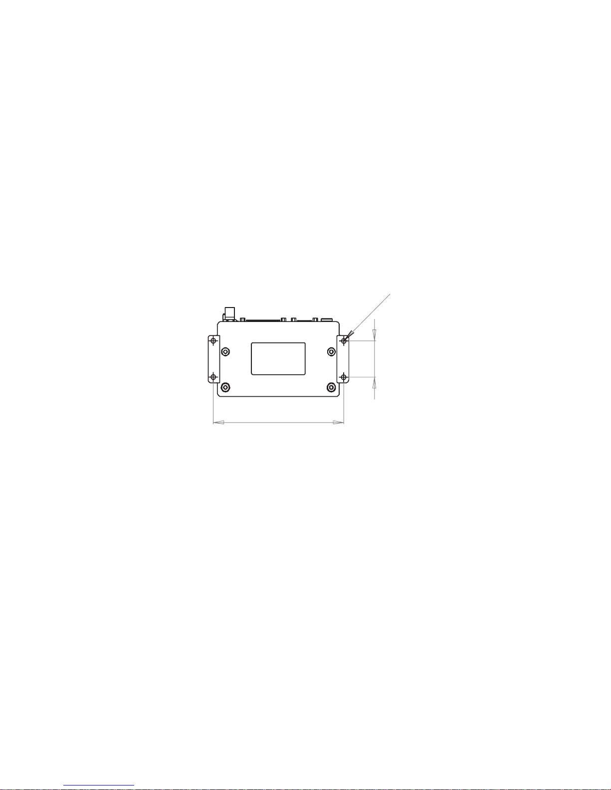
Fixing
We recommend that the TS-D400 is securely fi xed to a surface, either directly, or
with a suitable bracket. The fi xing hole centre dimensions are as shown.
Note: We do not recommend that the TS-D400 is fi xed by cable ties to any wiring
looms.
40mm
150mm
D
5m
m
5
Page 7

Connections
There are two types of power connection available, normally depending on whether
GPS is fi tted or not. The 2 pin circular connector is for connection to the power
supply only, when no GPS is fi tted, whereas the 4 pin circular connector includes an
ignition line. This ignition line can be used to power up the modem, or alternatively
the modem can be powered up by asserting the DTR (Data Terminal Ready) line
(see application notes).
The Mobitex antenna connector is a TNC female and the GPS antenna connector, if
fi tted, is an SMA female.
The TS-D400 has a standard 9 way D-Type RS232 port, the MASC control port,
which includes the DTR pin (see application notes).
The standard 25 way D-Type socket is the TTL interface representation of the
RS232 connector. It is the telemetry serial port which outputs the GPS, MASC,
Debug and programmable input/output lines. Please refer to the Application Notes
for further information. If standard RS232 signal levels are required on the D25
socket, a separate accessory lead is available to provide the necessary signal
inversion from TTL level to true RS232.
The MiniApp pin source current is 0.4mA when the output is high and 1.4mA when
the output is low. RS232 level signals are +4.5v to +12v for an asserted signal and
–4.5v to –12v for a de-asserted signal. Pins 2 to 8, 20 and 22 are standard RS232
pin connections. Pin 1 is +5V and not ground as per RS232.
Note: Incorrect connection may damage the modem and will invalidate the warranty.
It is recommended that any unused pins are pulled to their de-asserted level with
a 47K resistor. This is particularly important if the MASC Port is not used, to avoid
any unnecessary interrupts caused by fl oating pins slowing down the modem. The
MiniApp lines are polled, but allowing them to fl oat causes extra messages to be
sent, which if confi gured, can cause lines to be blocked awaiting replies. Refer to
the Application Notes.
Note: The TS-D400 Application Notes, and free demonstration software, are
available from the TS Mobile Web Site, www.tsmobile.co.uk.
6
Page 8

Start up and shutdown
Introduction
The TS-D400 operates on the Mobitex networks using Mobitex Asynchronous
Control Protocol (MASC Protocol). The TS-D400 modem is preconfi gured for use
with MASC as shipped from TS Mobile. Therefore, if only MASC is required, the
modem is ready for use immediately.
If additional features, such as input/output lines are to be used, the modem will
need to be confi gured. Please refer to the Application Notes. This may also include
PacketAT, which is a simple protocol which “sits on top of” MASC and provides
communication between modems. PacketAT is described in the Application Notes.
Start up routine
Please refer to the Application Notes.
Important Note: The modem should have power applied to the connector at all
times, but it is powered up by using either the ignition line or the DTR command
(RS232 port or TTL port). Once power has been applied to the mode, the modem
will begin its power up procedure after a 240mS delay.
The modem will start with all pins of the D25 at a ground state with the exception
of the DTR pin, which has an internal bias resistor to bias this high. The DTR pin
should be taken to ground as a clean edge during a clean power supply condition.
Shut down routine
The modem should never be powered down by interrupting the power as this
will leave the modem as active non contactable on the network, and stop the
modem saving important information at power down. The modem should always
be correctly shutdown, using commands as detailed in the application notes. The
method depends on whether Miniapp is confi gured or the MASC port is used, or
both.
7
Page 9

Safety and general information
Important information on safe and effi cient use of your Radio device
Exposure to radio frequency energy
Your modem is a high power radio transceiver. When it is on, it receives and also
sends out radio frequency (RF) signals. To help minimise human exposure to RF
electromagnetic energy, keep transmission time to 50% or less.
As with all radio devices, holding the antenna affects transmission quality and may
cause the radio to operate at a higher power level than required. Do not hold the
antenna when the radio is in use.
Do not use radios with damaged or modifi ed antenna, this may violate compliance
with relevant international standards.
Where prolonged human exposure is likely, the minimum separation from the
antenna should be 0.8m.
Electromagnetic interference/compatibility
Most modern electronic equipment is shielded from RF energy. However certain
electronic equipment may not be shielded against RF signals. The modem needs
to be switched off in any facility where posted notices instruct you to do so to avoid
electromagnetic interference or compatibility confl icts. Special care should be
taken near facilities such as hospitals or health care centres which may be using
equipment that is sensitive to external RF energy.
Medical devices (Pacemakers)
If you use any personal medical device, consult the manufacturer of your device to
determine it is adequately shielded from RF energy. Your physician may be able to
assist you in obtaining this information.
Vehicles with airbags
Air bags infl ate with great force. Do not place a radio in the area over an airbag or in
the airbag deployment area, any radio may be propelled with great force and cause
serious injury to the occupant of the vehicle.
Potentially explosive atmospheres
Turn off your modem prior to entering any area with a potentially explosive
atmosphere, unless it is a radio type especially qualifi ed for use in such areas. Do
not remove install or charge batteries in such areas. Sparks in potentially explosive
atmospheres can cause an explosion or fi re resulting in bodily injury or death.
Potentially explosive atmospheres include fuelling areas such as petrol stations,
below decks on boats, fuel or chemical transfer or storage facilities, vehicles using
liquid petroleum gas (such as propane or butane); areas where the air contains
chemicals or particles such as grain, dust or metal powders, and any other area
where you would normally be advised to turn off your vehicle engine. Areas with
potentially explosive atmospheres are often but not always posted.
8
Page 10

Warranty and repairs
The TS-D400 is a low maintenance device. Once installed it requires no ongoing
maintenance.
In the event that your TS Mobile D400 modem needs repair, return your radio to
an authorised TS Mobile supplier. Do not disassemble, modify or repair the unit
unless the work is carried out by a TS Mobile approved supplier. Incorrect assembly,
modifi cation or repair may cause irreparable damage to your unit and will invalidate
any warranty.
Care of the equipment
Do not immerse the D400 modem in water or other fl uids.
Do not use solvents or spirits for cleaning as this may cause
damage to the case materials.
Do not over tighten connection to the modem.
Disposal / Recycling
The TS-D400 is a Class 3 product in accordance with the Waste of Electrical and
Electronic Equipment (WEEE) Directive. Disposal of this class of equipment must be
carried out through an authorised recycling centre or contact your supplier.
●
●
●
9
Page 11

Declaration of conformity*
The TS-D400 range is a 10 Watt Wide-band (405 to 465MHz radio data modem
for use on the 8kB/s Mobitex Networks. The TS-D400 also comes with an optional
internal GPS module and is designated TS-D400gps. This is a licenced service,
restriction of use may apply in some countries.
This equipment is intended for use in:Austria, Belgium, Czech Republic, Cyprus, Denmark, Estonia, Finland, France,
Germany, Greece, Hungary, Ireland, Italy, Latvia, Lithuania, Luxembourg, Malta,
The Netherlands, Poland, Portugal, Slovakia, Slovenia, Spain, Sweden, Switzerland,
United Kingdom, Iceland, Liechtenstein, Norway, Bulgaria, Romania & Turkey.
This equipment can also be used worldwide, where a relevant Mobitex network is
available and where the equipment is approved for use.
We hereby declare that the above named product is in conformity to all the relevant
essential requirements of Directive 1999/5/EC.
Wir möchten hiermit bekanntgeben, daß das oben genannte Produkt in
Übereinstimmung mit allen erforderlichen Bedürfnissen der 1999/5/EC Direktive
seht
Certifi camos que el aparato es conforme con lo establecido en las disposiciones de
la Directiva 1999/5/CE.
Nous déclarons que le produit référencé ci-dessus satisfait aux exigences R&TTE
1999/5/EC qui lui sont applicables.
Relevant Specifi cations
This is a Class II product in accordance with the R&TTE Directive, 1999/5/EC.
*A signed and dated Declaration of Conformity is available on request.
Note: This document and others relating to the TS-D400 are available from the TS
Mobile Web Site, www.tsmobile.co.uk.
10
Page 12

Published by TS Mobile Limited.
Any queries regarding information in this manual, please contact the Technical
Services Group Leader at the above address.
Information provided in this document is believed correct at time of printing but is
subject to change without notice.
TS Mobile Limited will not accept liability for any loss, damage or costs howsoever
caused as a result of the information provided.
TS Mobile Limited
Version 2.0.0
This user guide is published by TS Mobile Limited. Improvements and changes
to this user guide necessitated by typographical errors, inaccuracies of current
information, or improvements to programs and/or equipment, may be made by TS
Mobile Limited at any time and without notice. Changes will be incorporated into
new editions of this user guide.
© TS Mobile Limited, 2012.
11
 Loading...