

TSMC Solar TS-130C1, TS-115C1, TS-120C1, TS-125C1, TS-135C1 Installation And Safety Manual
...
Installation and Safety Manual
Version 2.4, 12/1/2014
TS CIGS C1 Series
TS-110C1, TS-115C1, TS-120C1, TS-125C1, TS-130C1, TS-135C1, TS-140C1,
TS-145C1, TS-150C1, TS-155C1, TS-160C1, TS-165C1,
TS-130C1HV, TS-135C1HV, TS-140C1HV, TS-145C1HV, TS-150C1HV,
TS-155C1HV, TS-160C1HV
Revision History
Date
Version
Description
11/15/2012
1.0
Original version
5/8/2013
1.1
Add some statements about grounding hardware to comply UL 1703 Standard with its
revisions dated May 8, 2012. Moreover, the Electrical Ratings were changed for Models
TS-145C2, TS-150C2, and TS-155C2.
5/15/2013
2.0
Add a new Model TS-160C2 and deleted Models TS-125C2, TS-130C2, TS-135C2 and
TS-140C2 for UL certification.
10/1/2013
2.1
Update product specification in section 6A and add new models TS-165C2, TS-170C2 and
statements in Section 6, Installation and Operation
3/1/2014
2.2
Update product specification in section 6A and statement in Section 6D.
9/30/2014
2.3
Update 8.mounting methods and configurations
12/1/2014
2.4
Add a new model TS-165C1, TS-xxxC1HV(xxx=130~160) and WEEB grounding.
Moreover, the electrical ratings were changed for all models.

1. Introduction
With proper operation and maintenance, TSMC Solar modules will provide clean and renewable solar electricity
for years. This manual contains necessary installation, maintenance and safety information.
This Installation and Safety Manual will hereafter be referred to as “this manual”.
TSMC Solar Ltd., TSMC Solar Europe GmbH and TSMC Solar North America Inc. will all be referred to herein as
“TSMC Solar”.
TSMC Solar TS CIGS Series solar PV modules will hereafter be referred to as “TSMC Solar module(s)” or
“module(s)” or “the module(s).
Please retain this manual for your future reference.
2. Disclaimer of Liability
The use of this manual, the conditions and methods of installation as well as the operation, use, and maintenance
of TSMC Solar modules are beyond TSMC Solar’s control. Therefore, TSMC Solar assumes no responsibility and
expressly disclaims liability for loss, damage, injury or expense arising out of or in any way connected with such
installation, operation, use or maintenance of the modules. Furthermore, TSMC Solar assumes no responsibility
for any infringement of patents or other rights of third parties that may result from use of the modules, unless we
are automatically liable.
If you do not adhere to the instructions given in this manual, your rights under the TSMC Solar warranty may be
forfeited. Please check the warranty for the full details of your rights and obligations relating to your purchase and
use of TSMC Solar modules
3. General Information
This manual contains information regarding the installation and safe handling of TSMC Solar modules. All
instructions must be read and understood before attempting installation. If there are any questions, please
contact your sales representative or TSMC Solar for further information.
Installers must conform to all safety precautions in the manual when installing modules. Before installing, the
installer must become familiar with the mechanical and electrical requirements for PV systems.
Danger of death from electric shock!
Modules generate direct current (DC) electricity as soon as the front face is exposed to light.
Individual modules and especially connected systems can be an electrical hazard. Follow these general safety
and installation guidelines to avoid safety and electrical hazards.
WARNING

4. Warnings and Cautions
4.A Warning
All instructions must be read and understood before attempting to install, wire, operate, and/or maintain the
module. When modules are exposed to sunlight or other light sources, they generate DC electrical energy.
Contact with electrically active parts of the module such as terminals can result in burns, sparks, and lethal
shock whether the module is connected or disconnected.
Shock hazard increases as modules are connected in parallel, producing higher current, and as modules
are connected in series, producing higher voltage. The installer assumes the risk of all personal injury or
property damage that might occur during installation and handling of modules.
Do not disassemble, modify or remove parts of the module.
4.B Cautions
Use modules for their intended purpose ONLY.
Do not treat any portion of the module with paint or adhesives, to avoid damage to the module, inoperable
conditions, or reducing the module’s functionality.
5. Handling and Installation Safety
To avoid injury or damage:
Wear non-slip gloves.
Do not allow children or unauthorized persons near the installation site or module storage area.
Do not wear metallic rings, jewelry or devices while installing or troubleshooting photovoltaic systems.
Work only in dry conditions, with dry modules and tools.
Do not install the module where flammable gases or vapors are present.
Never leave a module unsupported or unsecured.
The back of the module must not be exposed to direct sunlight for extended periods of time during storage
or during the installation process to avoid the possibility of heat damage.
When disconnecting wires connected to a module that is exposed to sunlight, an electric arc may result.
Such arcs may cause burns, may start fires and may otherwise create problems. Be extremely careful!
Use only equipment, connectors, wiring and mounting structures suitable for use in a photovoltaic system.
Series connected modules should always be of uniform configuration and electrical specifications.
Cover the entire front surface of the modules with a dense, opaque material such as a cardboard box, when
working on a connected system cannot be avoided. Check for remaining voltage before starting, and
observe the relevant local safety regulations for such working conditions.
6. Installation and Operation
Photovoltaic systems must be installed by qualified and experienced personnel.
Install PV modules with a minimum spacing of 10mm between neighboring frames to allow for thermal
expansion.
Do not step on, or place objects on the module during or after installation. Although TSMC Solar modules
are quite rugged, the glass may be broken if it is dropped or hit by tools or other objects and the module will
no longer work properly. The module must not be exposed to concentrated sunlight, e.g. sunlight focused by
mirrors, lenses or other magnifiers.
The module frame is made of anodized aluminum, and therefore corrosion can occur if the module is placed
in a salt-water environment in contact with a rack made of another type of metal (Electrolytic Corrosion). If
required, stainless steel washers can be placed between the module frame and support structure to prevent
this type of corrosion.
Any module support structures that are to be used to support TSMC Solar modules must be wind rated and
approved for use by the appropriate local and civil codes prior to installation. In Canada, the installation
must be done in accordance with CSA C22.1, Safety Standard for Electrical installations, Canadian
Electrical Code, Part I.
Do not drill holes in the module frame
Any module without a frame (laminate) shall not be considered to comply with the requirements of UL 1703
unless the module is mounted with hardware that has been tested and evaluated with the module under this
standard or by a field Inspection certifying that the installed module complies with the requirements of UL
1703.
The module type has been qualified as “Application Class A” under IEC 61730-1.
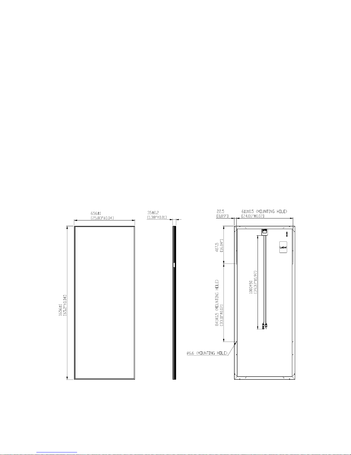
Figure 1 Module Physical Specifications
All measurements in mm [inches]

6.A Module Product Specification
C1 Product
Type of Modules (Series) TS-110C1 TS-115C1 TS-120C1 TS-125C1 TS-130C1 TS-135C1 TS-140C1 TS-145C1 TS-150C1 TS-155C1 TS-160C1 TS-165C1
Maximum power (P
max
) 110 115 120 125 130 135 140 145 150 155 160 165
Open-circuit voltage (Voc)
62.0 62.3 62.6 63.0 63.3 63.6 63.9 64.2 64.5 64.8 65.2 65.5
Short-circuit current (Isc)
3.61 3.61 3.61 3.61 3.61 3.61 3.61 3.61 3.61 3.61 3.61 3.61
Maximum power voltage (V
mpp
)
35.6 37.0 38.2 39.7 41.0 42.3 43.6 44.9 46.0 47.4 48.8 50.0
Maximum power current (I
mpp
)
3.09 3.11 3.14 3.15 3.17 3.19 3.21 3.23 3.26 3.27 3.28 3.30
Module efficiency 10.1% 10.6% 11.0% 11.5% 12.0% 12.4% 12.9% 13.4% 13.8% 14.3% 14.7% 15.2%
Certified by TUV SUD
Maximum system voltage (Vsys)
Maximum series fuse rating
Temperature coefficient of Pmax
Mechanical load
Dimension in inches (inch/mm)
Weight in lbs (kg)
Frame
38.5 (17.5)
Black Anodized Aluminum
TUV SUD
TUV SUD / UL
1000Vdc / 600Vdc(UL)
6A
-0.31%/℃
2400Pa (IEC) / 1695Pa (35lb/ft2, UL)
25.8 (656) x 65.2 (1656) x 1.4 (35)
C1HV Product
Type of Modules (Series) TS-130C1HV TS-135C1HV TS-140C1HV TS-145C1HV TS-150C1HV TS-150C1HV TS-160C1HV
Maximum power (P
max
) 130 135 140 145 150 155 160
Open-circuit voltage (Voc)
63.3 63.6 63.9 64.2 64.5 64.8 65.2
Short-circuit current (Isc)
3.61 3.61 3.61 3.61 3.61 3.61 3.61
Maximum power voltage (V
mpp
)
41.0 42.3 43.6 44.9 46.0 47.4 48.8
Maximum power current (I
mpp
)
3.17 3.19 3.21 3.23 3.26 3.27 3.28
Module efficiency 12.0% 12.4% 12.9% 13.4% 13.8% 14.3% 14.7%
Certified by
Maximum system voltage (Vsys)
Maximum series fuse rating
Temperature coefficient of Pmax
Mechanical load
Dimension in inches (inch/mm)
Weight in lbs (kg)
Frame
UL
1000Vdc(UL)
6A
-0.31%/℃
1695Pa (35lb/ft2, UL)
25.8 (656) x 65.2 (1656) x 1.4 (35)
38.5 (17.5)
Black Anodized Aluminum
Measured at STC: Irradiance 1000W/m2 and cell temperature 25°C (77°F) AM=1.5 after factory light soaking.
All ratings +/- 10%, unless specified otherwise. Specifications are subject to change
Pmax Tolerance (UL) after IEC Light Soaking is +10%/-5%, before IEC Light Soaking Tolerance is +/-5%
Refer to datasheet for potential increases in Pmax, Voc and Vmpp after post-installation light soaking.
6.B Electrical Installation
“Under normal conditions, a photovoltaic module is likely to experience conditions that produce more current
and/or voltage than reported at standard test conditions. The requirements of the National Electrical Code (NEC)
in Article 690 shall be followed to address these increased outputs. In installations not under the requirements of
the NEC, the values of ISC and VOC marked on this module should be multiplied by a factor of 1.25 when
determining component voltage ratings, conductor ampacities, overcurrent device ratings, and size of controls
connected to the PV output.”
The multiplying factor at conditions of an irradiance of 1250 w/m2, AM1.5 spectrum, and a cell temperature of
-10°C (+14°F) for Voc is 1.25 and at cell temperature of 75°C (167°F) for Isc it is 1.25.
For field connections, use approved PV Copper wire only, minimum No. 14 AWG (2.5mm2) wires insulated for
minimum of 90°C, rated for wet conditions and resist to ultra violet radiation (where exposed)
 Loading...