

Page 1
NON-LINEAR
JUNCTION DETECTOR
«LORNET-36»
USER MANUAL
CERTIFICATE
© TS-Market
Page 2

Contents
1.Introduction ..........................................3
2. Specications ..................................... 5
3. Delivery set, design and
accessories ............................................. 6
4. Purpose of the Detector Basic
Units .........................................................8
5. Safety Measures ............................... 15
6. Operation Order. ...............................16
7. Search Recommendation ................19
CERTIFICATE ........................................21
1. General .............................................. 21
2. Delivery Set ....................................... 22
3.Warranty .............................................22
4. Importer ............................................. 23
6. Claims Data ....................................... 23
2
Page 3

1.Introduction
MW non-linear junction detector “LORNET-36”
(further NLJD) is used for search and location of
electronic devices both in active and switch-off
state.
The detector operation is based on the property of
semiconductor components to generate a response
at the 2d and 3d harmonics when radiated by a
microwave probing signal.
Semiconductor components of articial origin
will have a higher level second harmonic while
semiconductor components of natural origin (e.g.
oxide lms) will have a higher level third harmonic
respectively.
An NLJD analyzes the 2d and 3d harmonics
response of the radiated objects, which enables
a quick and reliable identication of electronic
devices and natural oxide semiconductors.
The NLJD “LORNET-36” automatically nds the
best receiving frequency channel free of noise and
distortion providing awless operation even in the
complicated electromagnetic environment. Digital
processing of a demodulated signal used gives
maximum sensitivity.
3
Page 4

A high gain parabolic antenna (20 dB gain at
3600 MHz) used in the device increases detection
range of non-linear elements and provides
their exact localization in space. For operator’s
convenience the detector is equipped with a laser
pinpointing to indicate the place to which the
maximum power of the probing signal is directed.
There are two types of radiated signals:
pulse modulated carrier with a duty cycle 160
(Pulse).
-pulse modulated carrier with a duty cycle 20 (CW).
The CW mode is used to tap the detected signal in
the earphones to find active analog radio
microphones and to use the effect of acoustic
feedback to facilitate the search process.
The output power automatic control mode
significantly simplifies operator’s work.
“LORNET-36” simultaneously displays the 2d and
3d harmonics levels at its LED panel. Besides, the
2d and 3d harmonics levels can be estimated in
turn aurally by the click repetition rate reproduced
through a built-in loudspeaker or wireless
earphones.
4
Page 5

2. Specications
2.1. Radiated signal types
•
pulse modulated carrier with a duty cycle of
160 (pulse).
•
pulse modulated carrier with a duty cycle of
20 (CW).
2.2. Carrier frequency step 13 MHz within a tuning
range of (3581.5 … 3607.5) MHz. Automatic
frequency selection. Possibility of radiation at
the carrier frequency with a minimum noise
level in the 2d harmonic receiver path.
2.3. Maximum radiated power in 160
≥ 18 W
2.4. Maximum radiated power in 20 (CW) duty
mode ≥ 12 W
cycle
2.5. Manual or automatic control of the radiated
power level. Power control range of 22 dB
down from the maximum output power value
with 11 level gradations
2.6. Transmitting antenna gain at 3600 MHz
≥ 20dB with a directional pattern width at -3
dB level ≤16°.
2.7. Sensitivity of radio receivers better than -110
dBm (the rst LED lights up).
2.8. Receivers tuning frequencies equal to the
transmitter double and triple frequencies -
pulse mode
5
Page 6

7163…7215 MHz and 10744.5…10822.5 MHz
respectively.
2.9. Receiving path dynamic range ≥ 30 dB.
20 dB range of LED and 10 dB gain control
using the ATT button.
2.10. Time of continuous operation with a lithiumIon battery at the maximum radiated power:
• ≥3 hours in the pulse duty cycle mode;
•
≥2 hours in the CW duty cycle mode.
2.11. Device weight ≤1.6 kg.
Operating conditions:
2.12.
• ambient temperature 5…40ºC.
• pressure ≥ 450 mm of mercury
3. Delivery set, design and accessories
3.1. The device includes units and accessories
stated in the Table below:
Description Q-ty
Receiver-transmitter unit with control unit and
built-in battery container
Changeable Li-Ion batteries 2
Container for battery charging 1
Charger for receiver-transmitter unit (CH1) 1
Wireless accessories including: receiving device,
earphones and charger (CH2)
Technical Description & User manual, Certicate
(in one piece)
6
Package 1
1
1
1
Page 7
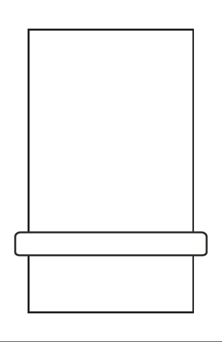
1
2 3
76
Fig.1.
5
4
- The appearance of the device and its charger are
shown in Fig. 1, where:
1. LED indicator;
2. Transceiver antenna unit combined with the
indicator ;
3. Control unit with an accumulator;
4. Parabolic antenna.
5. Screwed up cover of battery section
6.Container for battery charging;
7.Charger for receiver-transmitter unit (CH1);
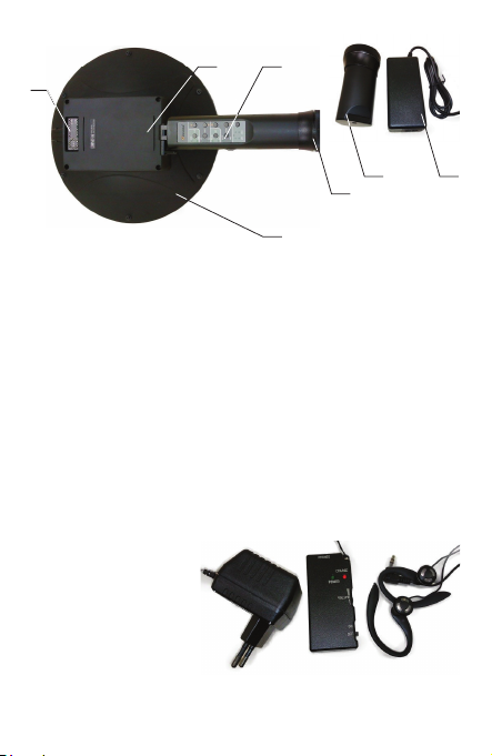
Fig. 2 shows
a receiver for
wireless phones,
its charger (CH2)
and head phones.
Fig.2.
7
Page 8

4. Purpose of the Detector Basic Units
4.1. The transceiver antenna with built-in LED
indicators is used for:
• Analysis of distortion and interference in the
instrument receiving path, which is made
each time the detector transmitter is switched
on. Therefore, if an interfering signal appears
during operation (in a complicated electromagnetic environment) it is necessary to turn the
detector transmitter off and on from time to
time thus selecting an optimal frequency automatically, which will provide the best sensitivity
as well as detection range of semiconductor
components.
• Generation of microwave probing signal, reception and digital processing of the 2nd and
the 3rd frequency harmonics. Simultaneous
display of the 2nd and the 3rd harmonics
levels gives the opportunity to distinguish with
a high reliability between signals of articial
semiconductors integrated in electronic devices and natural corrosive ones which may
appear at oxidized junction points of various
metals.
8
Page 9

• Demodulation of the 2nd and 3rd harmon-
ics response, their amplication to the level
required for tapping both by earphones and
a built-in loudspeaker. The amplication is
adjustable within a 20 dB range. The operator
can listen to demodulated signals of the 2nd
and 3rd harmonics in turn.
• Indication of the transmitter power level (1) as
well as of the 2nd (2) and 3rd (3) harmonics
levels (Fig. 3).
1 2 3
Fig. 3.
9
Page 10

4.2. Hinge joint of the transceiver antenna unit with
a knob (see Fig.4) is designed to transform
the unit into transportation position.
Besides, it helps the operator to ix the
antenna in a position convenient for search.
Fig. 4: 1- Fixing device; 2- Hinge joint.
2
1
Fig. 4.
4.3. The control panel is used to control operation
of the detector. It consists of the case
combined with a battery and xed on the
arm. The control board, buttons for operation
modes control and display LEDs are placed in
the package. The control buttons are divided
into two groups by their function: «AUDIO»
placed in the upper half of the panel and
«POWER RF» in the lower half. The
control panel is shown in Fig.5
10
Page 11

1
2
10
9
3
4
5
11
8
7
6
Fig. 5.
The following buttons refer to the «AUDIO» group:
1 - LEDs and LSTN button for switching of acoustic
indication to the output of the 2nd or 3rd
harmonics.
2 - LEDs and OUT button for switching acoustic
output to earphones or a built-in loudspeaker.
3 - LEDs and RF button for switching between
transmitter operation modes – PULSE or CW
The following buttons refer to the «POWER RF»
group:
4 - LEDs and PWR button for switching on/off
the probing signal transmitter. When the
NLJD is switched on the automatic mode
of output power control (AUTO) is set by
11
Page 12

default. To switch over to the manual mode of
output power control (MNL) press one of the
LEVEL buttons when a transmitter is turned
on. To return to the automatic mode turn the
transmitter off and then turn it on.
5, 6 - LED and ATT button for control sensitivity of
the transmitters of the 2nd and 3rd harmonics.
Lighting of each LED indicates decrease of the
transmitters sensitivity for 4 dB. Hence, when
ATT button is used the maximum sensitivity
decrease can be 20 dB.
7, 8 - LEVEL buttons for control of radiated signal
power in MNL mode. It is possible to set the
required power level by pressing LEVEL
button in AUTO mode before the probing
signal transmitter is turned on.
9,10 - Volume buttons for volume control
11 - Slide-type power switch
Functions of control panel indicators: continuous
light of any indicator corresponds to “on” position,
absence of light – to “off” position. Simultaneous
ickering o f a ll i ndicators o n t he p anel shows
that the battery is discharged and needs to be
replaced.
4.4. On the side surface of the control panel
12
Page 13

a slide-type power switch is placed. A slide
position corresponding to «ON» is
marked by a contrast point.
4.5. Battery charging is to be made with a battery
charger supplied with the instrument only. Using
other chargers is not allowed. For charging it
is necessary to connect a pin connector to the
end surface of the detector arm.
A red LED on the charger case is lighting while
charging. When a battery is completely
charged, the red LED goes out, and a green
LED lights up. Charging time of a fully
discharged battery does not exceed 6 hours.
4.6. Wireless telephones consist of a receiving
device and earphones. Appearance of the
receiving device and positions of control
units are shown in Fig.6
Using a power adapter supplied with the instrument
make sure with a help of the charge indicator that
the battery is completely charged. Using of other
power adapters is forbidden.
Connect head phones to the corresponding socket
of the receiving device.
Turn the receiving device on by a slide-type switch
13
Page 14

(control by the turn-on indicator).
Using volume control set a comfortable volume
level.
If the receiving
device is turned on when the
detector is off, then there is only a noise signal in
the head phones at higher volume. After turning
on the acoustic indicator signals corresponding to
the operating mode of the detector appear in the
earphones.
2
1
3
4
5
6
Fig. 6.
14
Page 15

1- “ON” indicator (lights at turn-on)
2 - Socket for phones connection
3 - Charge indicator (is lighting during charging)
4 - Socket for power adaptor
5 - Volume control
6 - Slide-type switch
5. Safety Measures
5.1. By requirements of electric safety the detector
corresponds to protection class 1 (according
to the Russian standard).
5.2. The instrument is to be operated only by
persons who have been duly instructed for
safety measures while working with electric
and measuring devices with open RF energy
radiators.
5.3. The microwave radiation power density level
from the detector transmitter is shown in the
Table below.
15
Page 16

Measure-
ments
In the
direction of
maximum
radiation
In the rear
semi-
sphere;
0.3m.
Mode P aver,
uW/cm²
Duty cycle 0,6% 3.6 9.36
Duty cycle 5% 44.1 77.8
Duty cycle 0,6% 0.19 1.7
Duty cycle 5% 1.88 7.7
P max,
uW/cm²
5.4. It is not recommended to direct the antenna
towards people. And it is not recommended
for an operator to stay in the direction of the
maximum radiation.
6. Operation Order.
6.1. Remove the detector from the package. If
necessary charge a battery. After the device
transportation at temperatures below 0°C it
is necessary to keep the device in the switchoff state at room temperature for at least 30
minutes.
6.2. Turn «LORNET-36» on by the power switch
placed on the arm. The 2nd and 3rd indicators
on the control panel will light up, indicating
16
Page 17

that the detector has been powered on.
One yellow LED should be lighting on the
antenna unit (a circle scale of the probing
signal power indicator). Its initial position
corresponds to the maximum power of the
probing signal. The probing signal transmitter
is off (it is turned on after pressing PWR button
only). The 2nd and 3rd harmonics indicators
should not light (ashing of the rst LEDs of
the 2nd and 3rd scales is permitted).
6.3. Turn the probing signal transmitter on
pressing PWR button. This will switch
on the transmitter pulse mode and the
automatic mode of signal power control. The
radiated signal power will change depending
on the signal level at the 2nd harmonic
receiver input. In the given mode the sound
information of the 2nd harmonic response is
applied to the loadspeaker or head phones.
When switching on mode 3-RD by pressing
LST on the control unit, the output power
of the transmitter is adjusted automatically
depending on the signal level at the 3rd
harmonic receiver input. Sound information
of the 3rd harmonic response is applied
to the loudspeaker or head phones.
17
Page 18

To switch over to the manual mode of the
probing signal power control (MNL indicator
lights up) press one of LEVEL buttons after the
probing signal transmitter has been turned on.
Using PWR button turn the probing
signal transmitter off and then turn
it on for a reverse switch over.
If it is necessary to tap the third harmonic
response turn on mode 3–RD using
LST button on the control panel.
During operation in premises with
electronic devices, you will normally have to
decrease the level of the probing signal by 2-4
points counterclockwise from the initial position.
The optimum level of the probing signal is
determined experimentally.
6.4. Simultaneous ashing of all indicators on
the control panel indicates that the battery is
discharged. In this case the power should be
turned off and the battery - replaced.
6.5. If a response signal is to be tapped by phones,
switch over acoustic indication to the head
phones mode pressing the corresponding
button on the control panel and turning the
wireless phones on.
18
a lot of
Page 19

Attention:
1) Do not direct the antenna towards the operator
and people nearby.
2) While operating the device constantly monitor
batteries state replacing them in-time (by the
indicators signal). The batteries must be kept
fully charged.
3) Charging should be done with a charger
supplied with the instrument only. Use of
undue chargers is strictly forbidden.
7. Search Recommendation
7.1. If possible remove electronic devices from
the room examined. If it is impossible, the
examination should be done at a decreased
radiated power.
7.2. Set the maximum radiated power level and
one of the operation modes of the receiver.
7.3. Using laser pointer direct the antenna to the
surface examined. Slowly moving the laser
spot along the surface under examination and
changing the orientation of antenna, analyze
changes in the signal received at the 2nd and
3rd harmonics visually by the indicator (aurally
the click repetition rate should be maximum).
19
Page 20

7.4. The received 2nd and 3rd harmonics levels
are analyzed by the number of LEDs lighting
on the corresponding indicator scale.
7.5. For a more accurate location as well as
for protection of receiving devices from
interference it is possible to decrease the
receivers sensitivity using ATT button.
7.6. When an articial р-n transition is found you
will normally see a stable lighting of the 2nd
harmonic indicator LEDs. While rapping at the
suspected place of a p-n transition, readings of
LEDs do not change.
7.7. When a natural р-n transition is found, you will
observe a stable lighting of the 3rd harmonic
indicator LEDs. While rapping at the examined
surface intensively, readings of indicators by
the 3rd harmonic will change, as a rule.
The search technique offered does not reect all
nuances which may appear in each exact
case, and represents a recommendation only.
20
Page 21

CERTIFICATE
1. General
1.1. Before operation thoroughly study User
Manual for «LORNET-36».
1.2.The Certicate is included in the delivery
set and should be always kept with the
instrument.
1.3. If the device is sent for repair or to a different
place during operation the Certicate is to be
shipped with the instrument.
1.4. Marks in the Certicate should be done in-
time.
1.5. All records in the Certicate should be
made by ink only, distinctly and carefully. All
unauthorized erasures, blots and corrections
are not permissible.
1.6. It is forbidden to make any notes or records in
the elds and on the cover of the Certicate.
21
Page 22

2. Delivery Set
Description Q-ty
Receiver-transmitter unit with control unit and
built-in battery container
Changeable Li-Ion batteries 2
Container for battery charging 1
Charger for receiver-transmitter unit (CH1) 1
Wireless accessories including: receiving device,
earphones and charger (CH2)
Technical Description & User manual, Certicate
(in one piece)
Package 1
1
1
1
3.Warranty
3.1.Warranty period for «LORNET-36» is
18 months upon supply to the customer.
3.2. Life time is 6 years.
3.3. If the device fails during warranty
period provided the customer has followed
all the operation, transportation and storage
rules, the manufacturer is to make the repair
free of charge or replace the device.
3.4.Warranty does not cover power elements.
22
Page 23

4. Contact Details
TS-Market Ltd.
Building 10-1 Sosnovaya Alleya, Zelenograd,
Moscow, the Russian Federation, 124489.
Tel.: +7(495) 638-8800
Fax.: +7 (499) 735-0491
www.ts-market.com
support@ts-market.com
6. Claims Data
In case of a package damage during transportation
claims are applied to the transportation organization
complying to the valid regulations.
If the delivery set is not complete or the NLJD is
damaged, provided the package is not damaged,
an Act is made together with a representative of
the manufacturer.
If a defect appears during warranty period, the
customer is to send the NLJD to manufacturer with
an accompanying letter, stating the reason of the
claim.
All claims with a brief description of encountered
problems and measures taken are recorded in
Table 1.
23
Page 24

Table 1.
Claim content Reason, mea-
sures taken
24
Notes
 Loading...