

Page 1

Operation manual
© TS-Market
Digital voice recorder
EDIC-mini LCD
Version 05.08.29
Page 2

Contents
2
Introduction ................................................................................................3
Purpose.......................................................................................................3
Delivery set .................................................................................................4
Basic technical and functional features ..................................................4
DVR overview .............................................................................................7
Display symbols.........................................................................................8
DVR operating ............................................................................................9
Prestarting procedures.......................................................................9
Battery installation and replacement ..................................................9
Earphone and remote control connection ..........................................11
Operating modes........................................................................................12
Record mode (REC)...........................................................................12
Playback mode (PLAY) ......................................................................15
Erasing mode (CLEAR)......................................................................16
Tuning mode (REC PR) .....................................................................17
Setup mode (SETUP) ........................................................................18
Profile setting mode ...........................................................................20
Recording startup by timer .................................................................22
Standby mode (Stop mode) ...............................................................23
Energy-saving mode ..........................................................................23
Admission levels ................................................................................23
Antialiasing median program filter......................................................24
Connection to computer............................................................................24
System requirements .........................................................................24
Connection .........................................................................................24
Firmware updating .............................................................................25
DVR accessories ........................................................................................26
External microphone with a compressor, combined with the remote
control ................................................................................................26
Phone talk record adapter..................................................................27
Record adapter for cellular phone with a stereo ................................27
connector
Troubleshooting: possible causes and corrective measures ...............28
Technical support ......................................................................................30
Control chart...............................................................................................32
Guarantee card...........................................................................................40
Page 3

Introduction
Thank you for purchasing the Edic-Mini LCD digital voice recorder
(DVR). Prior to operation, read the operation manual thoroughly.
Purpose
Voice recorders of theEdic-mini LCD series are professional devices
intended for making high quality recording of voice messages into built-in
flash-memory. You can playback recorded messages using
headphone and save them in your computer as standard audio files.
Voice recorders feature extremely small dimensions and weight, long
record time (varies with the model up to 600 hours), standby
operation (up to 1000 hours), and highly sensitive built-in microphone
with a wide dynamic range. Due to the absence of moving parts, the
DVR functions even under the conditions of strong vibration, dustiness,
and low temperatures.
The supplied USB adapter provides high-speed data exchange
between the DVR and the computer (1.5 Mb). The software supplied
on the CD makes it possible to save the recorded messages as
standard audio files, set the DVR parameters, and control
admission to the DVR functions. You may use your DVR for message
recording, as well as a flash-disc at the same time, to store and
transfer data of any format.
For the user's convenience, while operating the DVR, there is a push-
button manipulator (joystick) and a liquid-crystal display to indicate all
the information needed, including a built-in timer and a real time clock.
The DVR has a Voice Activating System (VAS) which effectively
compresses pauses in messages therefore increasing the actual
recording time. The pause length can be restored at further file
processing with the software supplied.
3
Page 4

4 5
Delivery set
- Edic-Mini LCD digital voice recorder
- Headphone
- USB adapter
- CD with software
- 2 batteries
- Operation manual
- Guarantee card
Basic technical and functional features
1.Available recording time in ExtraLongPlay mode (modified 2-bit ADPCM,
sample rate 8 kHz, 16 Kbit/s).
Index
Record time
Built-in flash memory size
560
560 min.(9.3 hours)
64 MB
1120
1120 min. (18.6 hours)
128 MB
2240
2240 min.(37.3 hours)
256 MB
4480
4480 min. (74.6 hours)
512 MB
8960
8960 min. (149.3 hours)
1 GB
17920
17920 min. (298.6 hours)
2 GB
The DVR features a SuperExtraLongPlay mode (modified 2-bit
ADPCM, sample rate 4 kHz, 8 Kbit/s), which increases the recording time
twice as much as regards the data in the table.
Page 5

- Supply voltage: 2.7-3.2 V;
- Operating temperature: -20- +50°C (68-122F);
- Maximum bandwidth:
- at playback on PC: 100-6000 Hz;
- at playback through the earphone: 100-3800 Hz;
- Sample rate: 16000, 8000, 4000 Hz;
- Codec capacity: 16 bits;
- Signal/noise ratio: 72 dB;
- Quality, formats and density of data record:
Without compression (linear), sampling rate is 16 kHz, 256 Kbit/s, k=16
Without compression (linear), sampling rate is 8 kHz, 128 Kbit/s, k=8
Without compression (linear), sampling rate is 4 kHz, 64 Kbit/s, k=4
Logarithmic compression, sampling rate is 16 kHz, 128 Kbit/s, k=8
Logarithmic compression, sampling rate is 8 kHz, 64 Kbit/s, k=4
Logarithmic compression, sampling rate is 4 kHz, 32 Kbit/s, k=2
Modified 4-bit ADPCM, sampling rate is 8 kHz, 32 Kbit/s, k=2
Modified 2-bit ADPCM, sampling rate is 8 kHz, 16 Kbit/s, k=1
Modified 4-bit ADPCM, sampling rate is 4 kHz, 16 Kbit/s, k=1
Modified 2-bit ADPCM, sampling rate is 4 kHz, 8 Kbit/s, k=0.5
where k is the coefficient, showing how many times the maximum
recording time decreases when record quality increases.
- Automated Voice Activation System (VAS);
- Antialiasing median program filter;
- Recording in the linear and circular modes (in the circular mode, the
buffer size is set in per cent of total memory size);
- Built-in microphone sensitivity: 7-9 m.;
- 8 user sets of record parameters (profiles);
- Random record delete;
- Real time clock;
- Battery charge indicator;
- USB interface with a PC, data exchange speed: 1.5 Mb;
Page 6

6 7
- Reliable data storage in flash-memory: over 10 years;
- Consumption in Standby mode with the indicator on: 0.14 mA;
- Consumption in Standby mode with the indicator off: 0.016 mA.
Antialiasing
Sample rate, kHz
Compression
On
Off
16 no 3.6 mА 2.8 mА
8 no 3.4 mА 1.8 mА
4 no 3.3 mА 1.6 mА
16 log1-16 3.4 mА 3.4 mА
8 log1-16 3.3 mА 1.9 mА
4 log1-16 3.3 mА 1.5 mА
8 ADPCM2,4 3.2 mА 2.5 mА
4 ADPCM2,4 3.2 mА 1.6 mА
With the VAS on and the signal below equils the threshold,
consumption does not exceed 0.2 ma. At
playback the consumption is 5-7 m A in all modes.
Page 7
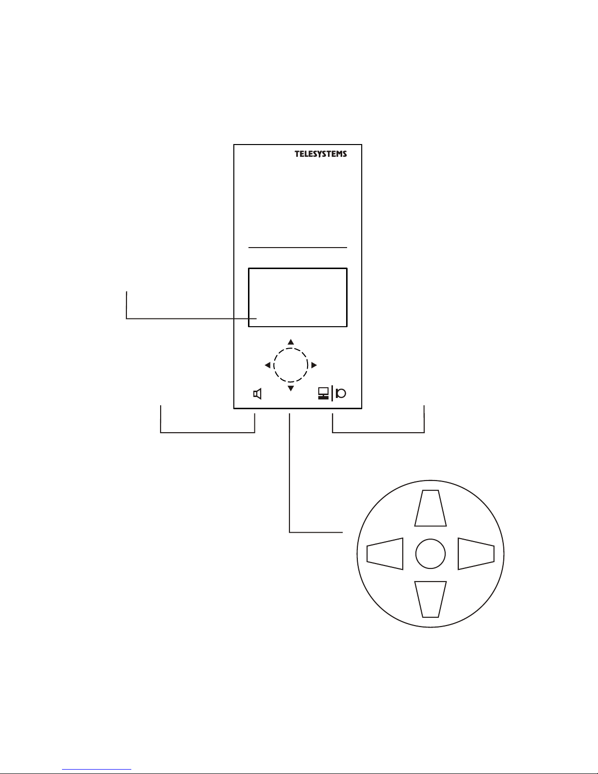
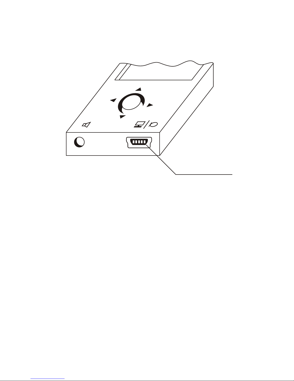
model B8
EDIC-mini LCD
up
down
enter
left right
Push-button joystick
Connector for external
microphone and
USB adapter
connector of headphone
EDIC-mini LCD B8 overview
LCD
DVR overview
Page 8
8 9
Display Symbols
- Indication of the DVR connection to PC by means
of the USB adapter.
- Battery charge indicator;
- Record mode indicator;
- Standby mode indicator;
- Playback mode indicator
1 - Symbol line
2 - Numeric line
3 - Alphabetic line
1
2
3
Page 9
DVR Operating
Prestarting procedures
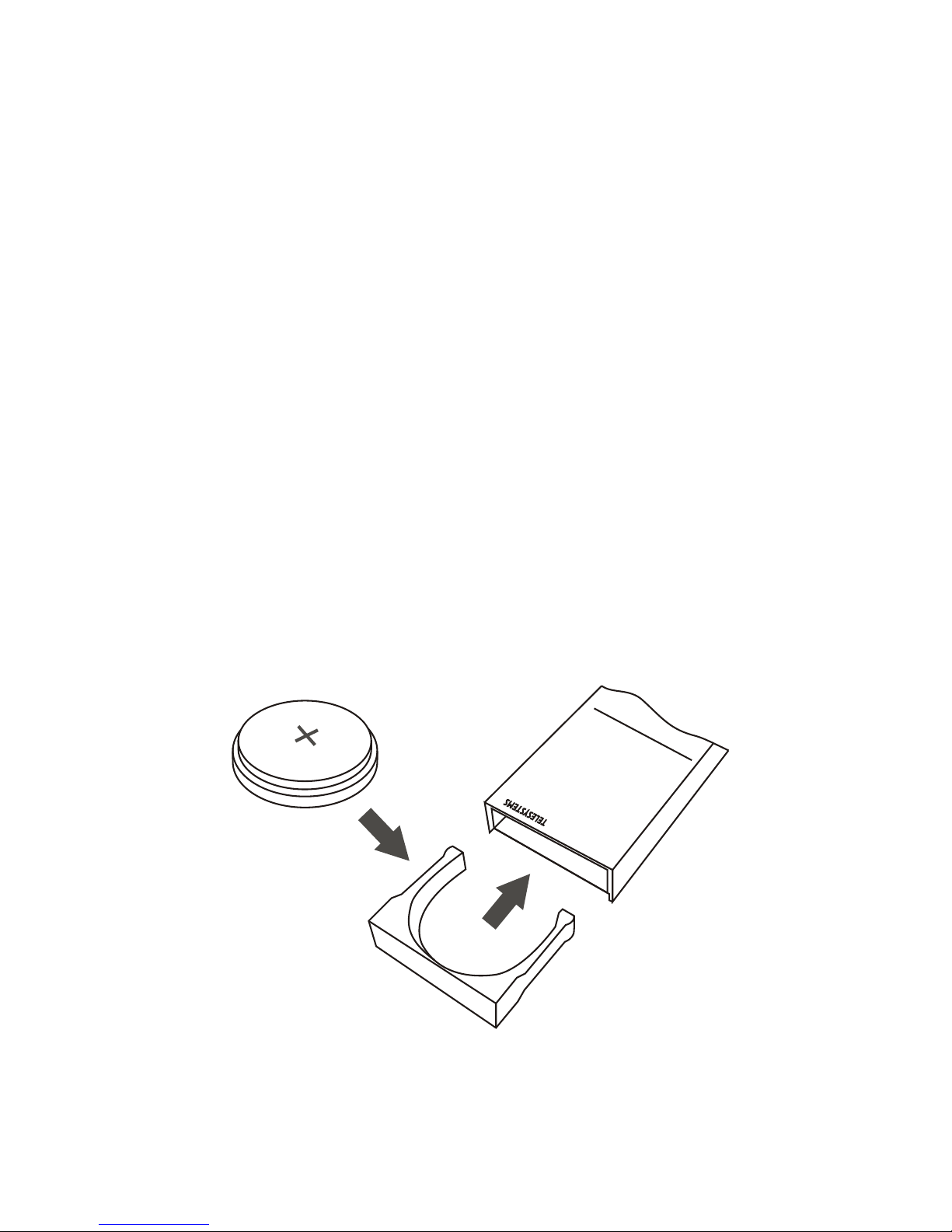
Battery installation
We do recommend that only the batteries, produced by well known
manufacturers should be used in the DVR. In this case you may
expect your DVR to work continuously. Other battery types of the
same dimension-type may provide less DVR operation time in
Record and Playback modes, even if they are called compatible and
announced to have better features.
When inserting the battery, make sure you have checked the polarity.
Warning!
Special attention should be paid to polarity while inserting the battery:
the positive battery contact is to be upward (the top side of the DVR is
where the joystick and the display are).
CR 2450
model B8
EDIC-mini LCD
Page 10
10 11
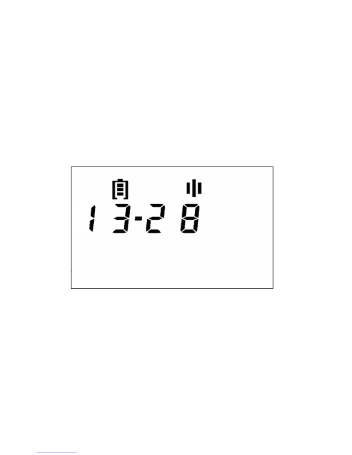
If the battery is inserted properly, the DVR will execute self-testing,
and you will see the total memory capacity and firmware version on
the display, then all the LCD elements will be indicated for a
moment. After that you will see the following information on the
display:
- In the symbol line battery charge indicator and mode symbol
(Stop mode);
- In the numeric line the current time (hours and minutes), the
separator blinks at a 2-second interval. (Fig. 1)
The DVR is in the Standby mode and ready to work. If let without a
push-button activity for a minute, the DVR goes to Sleeping
mode and the LCD display goes off. Push the joystick up to switch back it
on.
Fig.1
Page 11

Battery is fully
charged
Battery is
discharging
Battery is
discharged
Battery replacement
Battery charge indicator shows how much battery life is left.
If the battery is fully charged, the battery indicator border and three
lines inside will be shown on the display
If there is only the battery border on the display, it means that the
battery is discharged and should be replaced. When the battery is
discharged, the DVR does not react to the pressing or pushing of
buttons, and the display remains off.
You can replace the battery without switching off the DVR. At that it
can work for some seconds without the battery. Thus, if the battery
is replaced fast enough, the built-in real time clock does not reset.
Earphone and remote control connection
The headphone and remote control can be connected through the
headphone connector on the side part of the case. You should fully
insert the headphone plug into the connector.
Page 12
Operating Modes
You can select a mode with the push-button manipulator
(joystick) in accordance with the diagram. (See the control chart at
the end of the manual).
If it is left without a push-button activity for a minute, the DVR switches
to the Energy-saving mode and the LCD display goes off.
Push the button up to switch it back on.
Record mode (REC)
To start the Record mode, press the button once or twice, depending
on settings made when connecting to the PC.
On the display you will see:
In the symbol line battery charge indicator and mode symbol;
Socket for external
accessories
Page 13

1312
In the numeric line on the left: net recording time (hours and minutes),
the separator blinks at a 2-second interval; on the right: the current
profile number;
In the alphabetic line on the left: the percentage of available memory,
on the right: the number of the recording being made. (Fig. 2)
Fig.2
Push the joystick up to pause recording, PAUSE will appear on the
display.
Page 14

To continue recording, press the button once again.
If you push the joystick down, recording will stop, the DVR will go to
Standby mode.
If trere is no more free memory,the DVR will automatically go to Sleeping
mode.
Recording may be saved either in the cycle buffer mode or in the line
messages mode. The DVR can provide some memory size to the
cycle buffer. (See Profile setting)
Warning! When recording into the cycle buffer (cycle record), the
DVR will start recording into the record beginning (i.e. deleting the
previously recorded data), as soon as the provided memory space
comes to the end. The time of the current record will go on, but the
remaining memory size will stay constant on the display.
Each recording made is marked with the time and date by means of the
built-in real time clock.
You may adjust your DVR (see Setup mode) to record in the VAS
mode. This will allow you to compress the pauses in messages
efficiently therefore the available recording time increases. Using this system
saves memory in pauses, but stores information about time intervals.
The pause length can be restored at further file processing with the
14
Page 15

15
supplied software.
In the VAS mode, while recording into flash memory, the Record
symbol will be lit on the display. If the signal does not exceed the fixed
level, and it is not recorded into flash-memory, there will be Record and
Stop symbols on the display
You can adjust the VAS mode settings with the supplied software.
The VAS working algorithm is as follows: the DVR controller sleeps for
T1 time, then it switches on for T2 time and analyzes the signal. If it
discovers the X1 threshold exceeding by the signal during this time, the
controller attempts to discover the X2 threshold exceeding by T4 time
during T3 time. If the controller succeeds, the recording starts, otherwise
the recorder continues sleeping. The recording stops, if the signal does
not exceed the X3 threshold during T5 time and so on in cycle. The user
can set T and X values, corresponding to software settings, to confirm
to specific requirements.
Playback mode (PLAY)
When you push the joystick down, PLAY will appear on the display. If
you want to playback any recording, press the button to confirm
choosing the Playback mode. Push the button right or left to select the
recording number to be played. Then press the button, and the playback
of the chosen record will start. The display will show the following
information (Fig. 3):
- In the symbol line battery charge indicator and mode symbol;
- In the numeric line on the left: playback time (hours and minutes), the
separator blinks at a 2-second interval, on the right: volume level;
- In the alphabetic line on the left: the size of the record segment
played, as the percentage of the total record size, on the right: the
number of the recording being played.
Page 16

Fig. 3
You can change the volume by pushing the button up. The volume varies
vary from 0 (off) to 8 (max).
If there are no recordings to be played, EMPTY will appear on the display.
To exit this mode, push the button down.
Erasing mode (CLEAR)
To erase a record, push the joystick down twice. You will see CLEAR
on the display.
Page 17

1716
0
4
2
6
1
5
3
7
Extra high
Extra high VAS
Normal
Normal VAS
Super high
Super high VAS
Medium
Medium VAS
Sampling rate 16 kHz, linear (without compression),
256 Kbit/s
Sampling rate 16 kHz, linear (without compression),
VAS, 256 Kbit/s
Sampling rate 16 kHz, logarithmic compression (16
LOG), 128 Kbit/s
Sampling rate 16 kHz, logarithmic compression (16
LOG), VAS, 128 Kbit/s
Sampling rate 8 kHz, logarithmic compression (16
LOG), 64 Kbit/s
Sampling rate 8 kHz, logarithmic compression (16
LOG), VAS, 64 Kbit/s
Sampling rate 8 kHz, modified 4-bit ADPCM, 32
Kbit/s
Sampling rate 8 kHz, modified 4-bit ADPCM, VAS,
32 Kbit/s
Press the button to confirm choosing this mode. Push the joystick right
or left to select the number of the recording (NUM) to be erased and press
the button. The available memory size will be indicated on the display, in
percent according to the total size. If you press the button again, the next recording
will be offered to be erased. If you have erased all the recordings or there
are no recordings, EMPTY will appear on the display. It means that 100%
memory is free. Press the button up to exit this mode.
Tuning mode (REC PR)
The DVR provides eight settings of recording parameters
(profiles). The DVR has the following preset profiles in the factory
configurations. (Each profile contains its own set of recording parameters,
including quality and voice compression at recording, VAS
parameters, recording in linear/circular buffer). You can set profiles as
you wish.
Page 18

18
You can change the profile parameters using the Setup mode. (See
Setup mode) We recommend you to select the profile before
recording. For that, push the button down three times, you will go to the
Tuning mode. Then press the button, and by pushing it right or left, select
a profile (from 0 to 7). Press the button and PR SET will
appear on the display. It means that the selected parameters are set.
Then push the button up to go to the Standby mode.
Remember, that the record time depends on the record
quality: the higher is the quality, the shorter is the time. You may
approximately calculate the record time using the coefficient stated in
the technical characteristics. To do this, divide the maximum record
time of your DVR by the coefficient corresponding to the chosen
parameters. In the Tuning mode, if without a push-button activity for 14
seconds, the DVR will switch to the Energy-saving mode. The chosen
profile will be saved. These settings are also saved when replacing the
battery.
Setup mode (SETUP)
Push the button down four times to switch to the profile Setup mode.
Here you can set the real time, check the available memory size and format
it completely as well. Then press the button to enter the Setup mode.
Then, pushing the button down, you can select from the following
items (in circle):
1. Viewing the available memory size (MEM).
Press the button to view free memory in percent of the total memory
size.
Page 19

19
9 9
O O 2 II
Push the button up to return to the Setup mode.
2. Profile setting (PROF). (See Profile setting mode)
3. Real time setting (TIME). Press the button to enter this mode. Push
the joystick left to set hours, and right to set minutes. Then push it
down and left/right to set the day, month and year.
Then press the button, SET will appear on the display.
Push the button up to return to the Setup mode.
4. Memory formatting (FORMAT).
Warning! At memory formatting, all the recorded messages will be
lost.
Page 20

To format the memory, press the button. By pushing the button left or
right, select YES and press the button again. DONE will appear on the
display. Push the button up to return to the Setup mode.
If you do not want to format the memory, select NO, press the button or
push it up. The DVR will return to the Setup mode.
5. Switching the record on/ off by single and everyday timer.
(See Record startup on timer mode).
Profile setting mode
Select the Setup mode (push the button down four times, then press
it), then push the button down once and press it. The DVR is in the
Profile setting mode now.
You can select parameter values by pushing the joystick left or right,
and switch to the next parameter by pressing the button. Push the
joystick up to return to the Setup mode.
First of all, select the profile number (NUM) by pushing the button left
or right, and press the button. The DVR will offer to set (in cycle):
1. Audio sample rate (FREQ) of 4, 8 or 16 kHz.
20
I 6 O O O
Page 21

21
Set it by pushing the button left or right. Push the button down to go to
the next parameter setting. Push the button up to return to the Setup
mode (without saving the selected parameters).
If you press the button, the setting will be completed, and PR SET and
the profile number will appear on the display.
2. Audio compression format. Push the button right to select the
format, and left to select the parameter value.
- NO recording without compression;
- LOG logarithmic compression. You can set the sensitivity parameter
(1, 2, 4, 8 or 16) by pushing the joystick to the left. The parameter depends on
recording conditions. You should set a low parameter value to make a
high quality record of a weak signal; the strong signal will be recorded
with distortion. If the parameter value is big, loud signals will be
recorded at high quality, but low signals can be fuzzy.
- ADPCM Adaptive Differential Pulse Code Modulation. You can set
the parameters (2 or 4) by pushing the joystickto the left.
You may set the following quality, formats and density of the data
recording:
- Without compression (linear), sample rate is 16 kHz, 256 Kbit/s, k=16
- Without compression (linear), sample rate is 8 kHz, 128 Kbit/s, k=8
- Without compression (linear), sample rate is 4 kHz, 64 Kbit/s, k=4
- Logarithmic compression, sample rate is 16 kHz, 128 Kbit/s, k=8
- Logarithmic compression, sample rate is 8 kHz, 64 Kbit/s, k=4
- Logarithmic compression, sample rate is 4 kHz, 32 Kbit/s, k=2
- Modified 4-bit ADPCM, sample rate is 8 kHz, 32 Kbit/s, k=2
- Modified 2-bit ADPCM, sample rate is 8 kHz, 16 Kbit/s, k=1
- Modified 4-bit ADPCM, sample rate is 4 kHz, 16 Kbit/s, k=1
- Modified 2-bit ADPCM, sample rate is 4 kHz, 8 Kbit/s, k=0.5
where k is the coefficient, showing how many times the maximum
recording time decreases at record quality increase. You should
Page 22

remember: the higher is the quality, the less is the time. You may
approximately calculate the record time with the parameters set,
dividing the maximum record time of your DVR by the coefficient
appropriate to the selected parameters.
Push the button down to go to the next parameter.
Push the button left or right to select VAS or to stay in the normal mode
(NORM). Then push the button down.
You will see LINE on the display which means the line record mode is
on. Push the button left or right (one time) to select cycle record mode.
The figure in the Cycle mode means the buffer size in percent of total
memory size.
Press the button, when you have finished setting the parameters. PR
SET and the profile number will appear on the display.
22 23
O
Recording startup by timer
The DVR can start and finish recording by the timer. There
are two different timers: a single and everyday timer.
Single timer starts and stops recording at preset time (minutes, hours,
day, month and year).
Everyday timer starts and stops recording at preset time of the day
(minutes and hours). It will work day after day until the timer is
switched off.
Page 23

You can set the time accuratly within seconds, using a PC. It is possible
to view the starting and finishing time (within minutes) and switch
on/off timers from the DVR menu.
The timer starts/stops recording only if the USB is not connected, and
the DVR is not in Standby mode due to a battery discharge. If the
recording was on when the timer started, it will continue. If the
user interrupts recording (which was started by the timer), he/she has
to restart recording manually, otherwise the record will stop.
Standby mode (STOP mode)
When switched on, the DVR is in the Standby mode for some time. You
can see the real time and battery charge level on the display. Press the
button (once or twice, depending on the DVR settings), to start
recording. Pushing the button down, you may select modes
(Playback, Erasing, Tuning and Setup modes). If without a push-button
activity for minute, the DVR switches to the Energy-saving mode, the
LCD display goes off. Push the button up to switch it back on.
Energy-saving mode
If without a push-button activity for minute, the DVR switches to the
Energy-saving mode. The DVR goes to this mode from most other
modes if there is no push-button activity for a minute. The LCD goes off
then. If the device is in the Setup mode, the DVR will switch to the Energysaving mode having saved the parameters chosen by you.
Push the button up to switch the display on.
Press the button if you want to go to the Record mode.
Admission levels
To make the DVR convenient to use (data failure protection, protection
against accidental actions or unauthorized operation), there are three
levels of admission to DVR functions available from joystick, using the
Page 24

supplied software. (See the diagram in the enclosed paper)
First admission level (USER): only recording is possible in the DVR.
Second admission level (OPERATOR): Record, Playback, Erasing
and Tuning modes are available.
Third admission level (ADMIN): complete admission to all modes
and parameter setting.
Antialiasing median program filter
There is an opportunity of applying an antialiasing median program
filter to improve recording (especially with the sample rate of 4 and 8 kHz)
and playback quality. You may activate this function with the software.
It should be borne in mind that applying the filter will result in DVR
current drain increase and battery resources decline. (See the current
drain table)
Connection to Computer
System requirements
To be able to operate with the DVR and set parameters setting your PC
should have:
1. Operating system Windows 9x/Me/NT/2000/XP.
2. Sound card available.
3. USB plug available.
Connection
The DVR is to be connected into the USB socket of the PC through the
supplied USB adapter.
The DVR should be connected to the adapter through the connector
on the right side, with a display picture.
24 25
Page 25

Socket for external
accessories and PC cable
You will see the at the beginning of the symbol line.
Warning! The DVR does not react to joystick movements, with the
adapter connected.
To operate the DVR, you should install the software from the supplied
CD.
The software has a user-friendly interface, and no special skills are
required to connect the DVR.
Firmware updating
To update the firmware you should:
1. Download the updated firmware from the manufacturer's web site;
2. Unpack the archive with two files in one folder;
3. Remove the battery from the DVR;
4. Connect the adapter;
5. Push the joystick in any direction;
6. Keeping the button pressed and the adapter connected to the DVR,
insert NEW or NOT DISCHARGED battery into the DVR;
Page 26

7. Start the exe-file;
8. Then follow the instructions in the console application window and
wait until the updating is completed (1-3 minutes);
9. Remove the battery and insert it again in 10 seconds. At switching
on, the DVR will indicate the new firmware version.
Warning! Be sure that the battery is not discharged (no empty “lines”
must be indicated on the display) to succeed in updating.
If the firmware updating failed for some reason (battery discharged,
computer switched off or adapter disconnected during the updating
process) and the DVR did not switch on with the power supplied just
repeat the procedure again. All the audio files recorded and DVR
settings will be saved with the firmware updating.
DVR Accessories
Warning! When purchasing, please, do mention the DVR type you
buy accessories for.
You may use accessories of type 3 with this DVR model.
1. External microphone with a compressor, combined with the
remote control
The external microphone has relative sensitivity of +6 dB in the far
zone (far than 1 meter) and -6 dB in the near zone (nearer than 1
meter) against the built-in microphone. For connection, you should
use the special connector for the external microphone, which is on the
right side of the case.
26 27
Page 27

Socket for external
accessories
Connecting the external microphone will disable the built-in
microphone; only the external microphone will be used at recording.
The remote control is a push-to-lock button. It allows the user to start
and stop recording remotely. Press the button and keep it pressed for
more than 0.5 second to enter the Record mode. Release the button
for more than 0.5 second to go to the Stop mode.
The DVR will go to the Record mode from other modes if you press the
button on the remote control and keep it pressed for more than 0.5
second. Release the button for more than 0.5 second to go to the
Standby mode.
2. Phone talk record adapter
This adapter makes it possible to record phone talks. It is connected to
the optional DVR unit connector. With the supplied software you
should adjust the configuration to automated recording of phone talks.
Then the DVR will automatically start recording at raising the
telephone receiver and stop at putting it back.
3. Record adapter for cellular phone with a stereo connector
This adapter makes it possible to record cellular phone talks. A stereo
connector should be provided for in the cellular phone to use this
application. The adapter is connected to the optional DVR unit connector. With the
supplied software you should adjust the configuration to automated
recording of cellular phone talks.
Page 28

Troubleshooting: possible causes and corrective
measures
When using the DVR at low temperatures, slowing down and
decreased operation speed are possible picture in the LCD display
dithers and/or changes slowly. This is not troubleshooting.
Problem
Possible causes
Possible corrective
measures
After inserting the
battery, there are no
symbols indicated
on the display. The
DVR does not react
to joystick pushing.
There is a message
ERR_XX on the
display. It goes off
only at power
disconnecting.
The DVR does not
start recording.
The battery is
discharged; the
battery polarity is not
observed.
DVR failure.
There is no free
memory.
Replace the battery.
Insert the battery
according to the
indicated polarity.
The DVR needs
repairing in the
service center.
Clear the memory.
Delete some
messages.
28 29
Page 29

Problem
Possible causes
Possible corrective
measures
The DVR does not
switch to the record
mode and does not
react to joystick
pushing.
There is no sound
heard in the
earphone in the
Playback mode.
The DVR does not
connect to the
computer.
The battery is
completely
discharged.
1. The volume is not
adjusted.
2. The headphone is
not completely
inserted.
3. The headphone is
broken.
The USB adapter
drivers are not
installed.
Replace the battery.
1. Set a higher
volume.
2. Insert the head
phone completely.
3. Try another head
phone.
Install/reinstall
drivers for the USB
adapter.
Page 30

Technical Support
You can get technical support comes through e-mail:
support@ts-market.com,
free of charge.
New software versions are free for downloading on the company web site:
http://www.ts-market.com.
Should anything in the operation manual be unclear, be sure to
contact the manufacturer for clarification.
30 31
Page 31

Page 32

ENTER ENTER
ENTER ENTER
ENTER ENTER
REC_PR
(profile number selection)
CLEAR
(record number selection to delete)
PLAY
(record number selection to play)
Normal state
(enables to manage the recording)
DOWNDOWN DOWNDOWN
SETUP
EDIC-mini LCD B8 menu control chart
32 33
Page 33

The first (the lower) access level
Record number selection
LEFT-RIGHT
LEFT-RIGHT
LEFT-RIGHT
Record number selection
Profile number selection
The second (mean) access level
Return to the normal state
Return to the normal state
Return to the normal state
The third (top) access level
(see the next double page)
Page 34

ENTER
ENTER
ENTER
ENTER
ENTER
ENTER
SETUP
MEM
PROF
TIME
FORMAT
TIMER
DOWN DOWNDOWNDOWN
DOWN
REC_PR
(profile number selection)
34
Page 35

Free memory volume
Profile setup*
Time and date setup*
Timer setup*
Formatting*
The third (top) access level
Return to SETUP
Return to SETUP
Return to SETUP
Return to SETUP
Return to SETUP
The second (mean) access level
(see the previous double page)
* the detailed chart of this option can be found on the next double pages
35
Page 36

Profile setup
Time and date setup
Formatting
Number selection
ENTER
ENTER
36
Page 37

Formatting
Sample rate selection
Hours and minutes setup
Compression type selection
Date and month setup
VAS turning on/off
Year setup
Yes / No
LINE/CYCLE (quantity of circles)
ENTER
ENTER
DOWN
DOWN
DOWN
DOWN
DOWN
37
Page 38

Timer setup ONCE
DAILY
ENTER ENTER
38
Page 39

Return to SETUP
Return to SETUP
Record beginning setup
Record beginning setup
Record end setup
Record end setup
ON / OFF
ON / OFF
ENTER
ENTER
ENTER
DOWN
DOWNDOWN
DOWN
39
Page 40

Developed and produced by Telesystems Ltd.
Guarantee card
Telesystems company undertakes obligations of guarantee repairs of
the product within 1 year from the date of sale. Claims for guarantee
repairs are not accepted at:
- operation rules violating;
- mechanical damages;
- absence of Telesystems' stamp on the present document.
All the questions concerned returning and exchanging the product,
are solved in accordance with the Consumer protection laws.
Warning! The guarantee does not cover batteries.
Number ____________
Model:
B8-560 B8-1120 B8-2240
B8-4480 B8-8960
Quality control department ___________
Date of sale __________
Seller ____________
Address:
B.10-1, Sosnovaya alleya, Zelenograd, Moscow 124489,
the Russian Federation
Phone: +7 (495) 530-10-01
Fax: +7 (495) 535-04-91
E-mail: support@ts-market.com
http://www.ts-market.com
 Loading...