

Page 1
Page 2

2
Index
IndexIndex
Index
TECHNICAL SPECIFICATIONS 4
MECHANICAL MOUNTING 4
ELECTRICAL CONNECTIONS 5
TERMINAL BOARD DESCRIPTION 5
CONNECTION WITH EXTERNALLY POWERED ENCODER 6
CONNECTION WITH SELF-POWERED HALL SENSOR 6
OUTPUTS CONNECTION WITH NPN LOGIC 6
AC OUTPUTS CONNECTION 6
USE 7
KEYBOARD DESCRIPTION 7
SETUP PROCEDURE 7
WORKING PARAMETERS SETTING 9
WORKING DIAGRAM 10
ERROR MESSAGES 11
WARRANTY 11
Page 3
3
This device allows you to monitor speed of axis motion and to compare this
value to two setpoints you can pre-program according to your needs. Every
setup setting and work parameter are stored in EEPROM module to guarantee
reliability and working assurance.
This manual provides all the necessary information for a correct installation and use of this device; it is strictly
recommended to read carefully the following instructions.
Entity Elettronica does not assume any responsibility for injuries or damages for persons or things deriving from noncompliance with the instructions in this manual; It does not assume any responsibility for eventual inaccuracy and
reserves the right to modify partially or totally the device features and documentation.
Technical data in this manual include a tolerance of +/- 10%.
Version Changes Date of changes
0 New Operating Manual; October 1997
1 Aesthetic and text changes; March 2001
2 New keyboard images; text structure remake. November 2002
Page 4

4
TECHNICAL SPECIFICAT
TECHNICAL SPECIFICATTECHNICAL SPECIFICAT
TECHNICAL SPECIFICATIONS
IONSIONS
IONS
Electrical Specifications
Power supply
24 – 115 – 230 Vac +/- 10%
50/60Hz
Power consumption 5 VA
Output power supply 12 Vdc 60 mA +/- 5%
Step frequency 1 MHz
Electromagnetic
immunity
In accordance with EN 50082-2
Electromagnetic
emissions
In accordance with EN 50081-2
Memory EEPROM
Display
6 digit h=14mm
+ 1 digit h=8mm
Mechanical Specifications
Container
Self-extinguishing plastic
DIN 48 x 96 x 124 mm
Container protection
degree
IP20
Front panel protection
degree
IP62 (device mounted on a panel)
Weight 370 gr
Keyboard
Vetronite covered with Scratch-resistant
polycarbonate
Operating Temperature 0÷40 °C
Transport and storage
temperature
-25 ÷ +70 °C
Operating Humidity 90%
MECHANICAL MOUNTING
MECHANICAL MOUNTINGMECHANICAL MOUNTING
MECHANICAL MOUNTING
This device container has been designed for panel mounting: make an hole as described in the picture at the bottom of
the page, insert the device and fix it with provided brackets.
Avoid to place the instrument in wet and dirty areas. Be sure that the device slot is not subjected to vibrations and big
temperature variations.
Install the device as far as possible from electromagnetic disturbances to avoid bad device working.
frontal view
side view
back view
mounting hole dimensions
Page 5
5
ELECTRICAL CONNECTIO
ELECTRICAL CONNECTIOELECTRICAL CONNECTIO
ELECTRICAL CONNECTIONS
NSNS
NS
TERMIN A L BOARD D E SCR
TERMIN A L BOARD D E SCRTERMIN A L BOARD D E SCR
TERMIN A L BOARD D E SCRIPTIO N
IPTIO N IPTIO N
IPTIO N
1
CH A Encoder input: A channel
2
CH B Not used
3
CH Z Not used
4
ABL Not used
5
+ Positive supply for encoder
6
- Negative supply for encoder
7
COM Outputs common
8
OUT 1 Output 1: first active threshold
9
OUT 2 Output 2: second active threshold
13
VAC Power supply
14
VAC Power suppply
Digital inputs
Opto-insulation 2500 V rms
Load current 10 mA
Impedance 1 kOhm
Polarization NPN
0 logic state voltage 0V + 6V
1 logic state voltage 10V + 12V
Digital outputs
Opto-insulation 2500 V rms
Commutable load
AC-DC
(NPN-PNP)
Maximum operating
tension
40 Vac/dc
Maximum current 500 mA
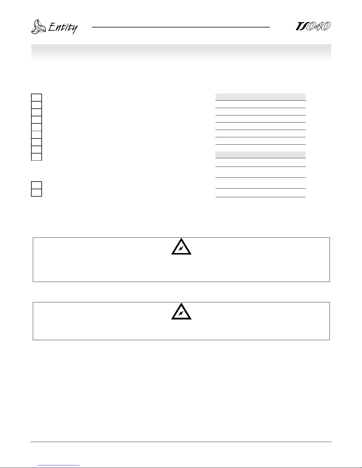
Connect only one conductor for each terminal and be sure that the power supply is as indicated on the back of the
device; use only cables properly insulated for operating tensions and temperature; keep power cables separated from
control cables.
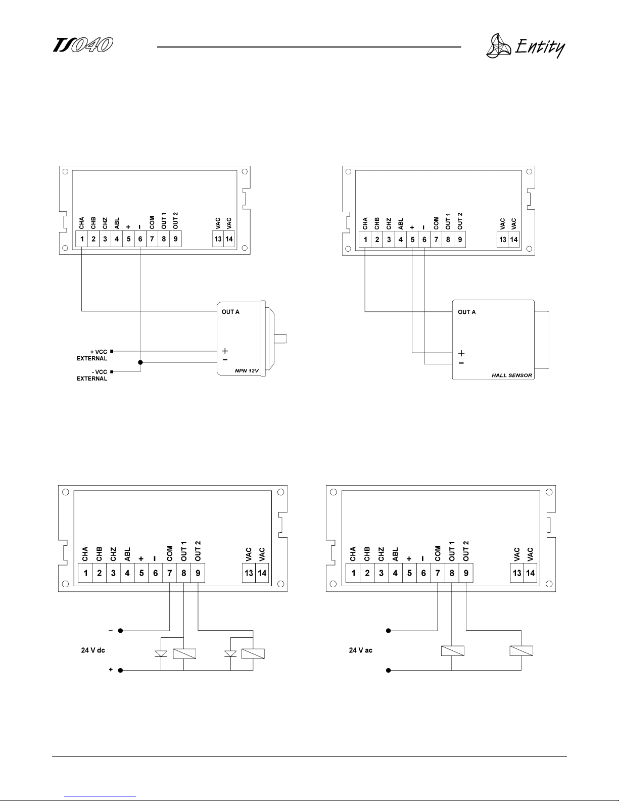
Be very careful when connecting the device and follow the indications provided in the following diagram. Be sure that
the device is not connected to the power supply when carrying out all the electrical connections.
If the malfunction of this device may injures persons or damage things, it is stricly recommended to
install mechanical devices or protections to guarantee safety!
Page 6
6
CONNEC T I ON WIT H E XTE
CONNEC T I ON WIT H E XTECONNEC T I ON WIT H E XTE
CONNEC T I ON WIT H E XTERNALL Y
RNALLY RNALLY
RNALLY
POWERE D ENCODER
POWERE D ENCODERPOWERE D ENCODER
POWERE D ENCODER
CONNEC T I ON WIT H S ELF
CONNEC T I ON WIT H S ELFCO N N E CTION W I TH SELF
CONNEC T I ON WIT H S ELF---- POWERE D
POWERE D POWERE D
POWERE D
HALL S E N SOR
HALL S E N SORHALL S E N SOR
HALL S E N SOR
OUTPUT S CONNEC T I O N W
OUTPUT S CONNEC T I O N WO U T PUTS C O N N ECTION W
OUTPUT S CONNEC T I O N WITH N P N LOGIC
ITH N P N LOGICITH N P N LOGIC
ITH N P N LOGIC
AC OU T P U TS CON N
AC OU T P U TS CON NAC OU T P U TS CON N
AC OU T P U TS CON N E C T ION
ECTIO NE C T ION
ECTIO N
Page 7
7
USE
USEUSE
USE
KEYBOA R D DESCR I P T ION
KEYBOA R D DESCR I P T IONKEYBOA R D DESCR I P T ION
KEYBOA R D DESCR I P T ION
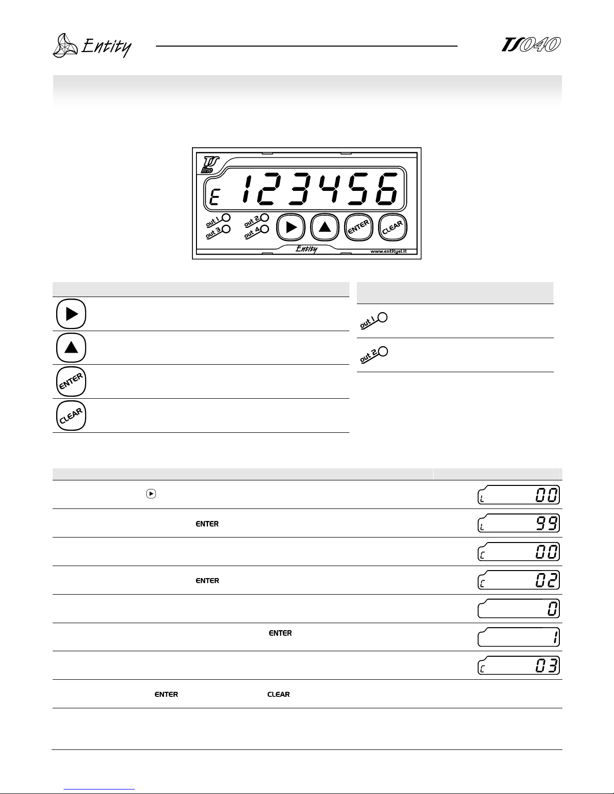
Key Normal mode Set-up mode
Start set-up mode; Shift to the right the flashing digit;
- Increment flashing digit;
- Enter value;
- Reset visualized value;
LED Meaning (if lighted)
“OUT 1” output is on (first threshold);
“OUT 2” output is on (second threshold);
SETUP P R OCEDUR E
SETUP P R OCEDUR ESETUP P R OCEDUR E
SETUP P R OCEDUR E
Description Display
To start setup mode, push ; “L00” will flash on the display;
Enter “99” with arrow keys, confirm with ;
“C00” will flash on the display;
Insert the parameter code and then push ;
On the display will appear the value of the chosen parameter;
Change the value with arrows keys as desired and confirm with ; the value will not be accepted if goes
behind its limits;
The next parameter code will appear on the display;
To continue with setup, push ; to exit setup mode, push four times.
Page 8
8
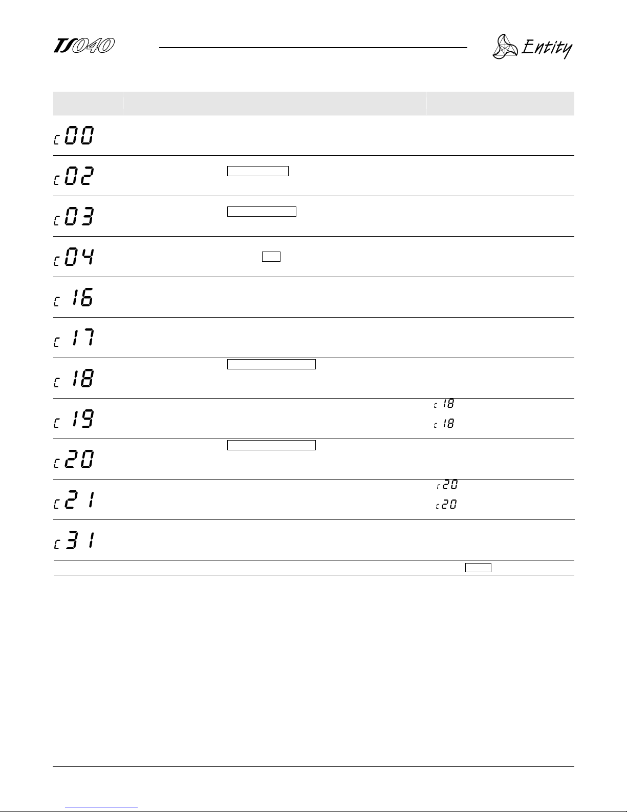
Parameter
code
Function Range and allowed values Notes
Show device code; -
Show device code and firmware version
alternately;
Working parameters
modification;
0
Active;
1
Inactive;
Decimal point;
0
Inactive;
1-5
from 1 to 5 decimal digit;
Division ratio;
00.00÷999.999
Default =
1.00
Division ratio = (encoder frequency)/(desired value);
First treshold; From
000000
to
999999
;
Second treshold From
000000
to
999999
;
OUT 1 logic;
0
Positive logic;
1
Negative logic;
2
Positive pulse;
3
Negative pulse;
Timer OUT 1;
from
00,00
to
99,99
seconds;
if =0 or 1, the set value delays
OUT 1 activation;
if = 2 o 3, the set value is the
pulse duration;
OUT 2 logic;
0
Positive logic;
1
Negative logic;
2
Positive pulse;
3
Negative pulse;
Timer OUT 2; from
00,00
to
99,99
seconds;
if =0 or 1, the set value delays
OUT 1 activation;
if = 2 o 3, the set value is the
pulse duration;
Speed value acquisition
time;
from
0,1
to
9,9
seconds;
Set the maximum time between one
speed visualization and the other;
Bold and framed values are default ones;
Page 9
9
WORKIN G PARAMET E R S S
WORKIN G PARAMET E R S SWORKIN G PARAMET E R S S
WORKIN G PARAMET E R S SETTIN G
ETTIN GETTING
ETTIN G
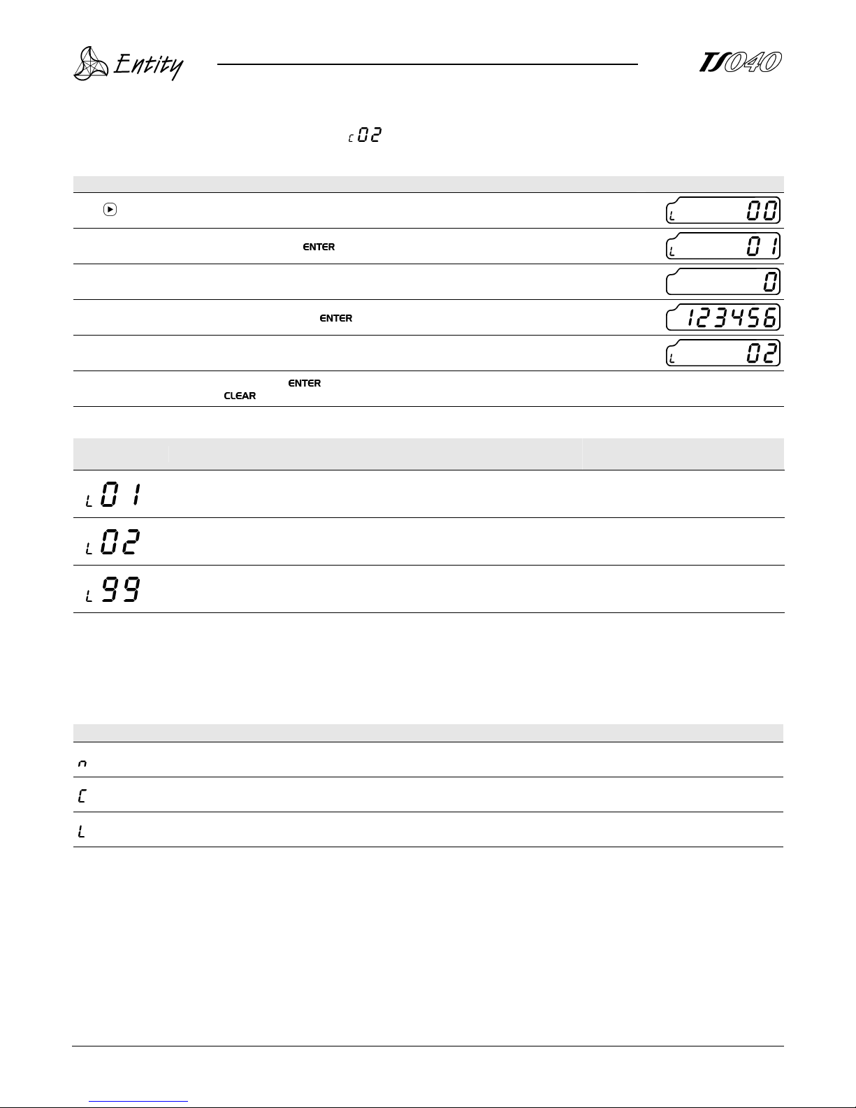
WARNING: these settings are permitted only if is 0 (zero).
Description Display
Push ; “L00” will flash on the display;
Insert desired parameter code and confirm with ;
The value of the chosen parameter will appear;
Change the value with arrow keys and confirm with ;
The value of the next parameter will appear;
To continue working parameters setup, push ;
To exit from setup mode, push twice.
Parameter
code
Function Range and allowed values Notes
Firs threshold; from
000000
to
999999
Second threshold; from
000000
to
999999
Setup code; Start the setup mode;
Prefix meaning
Measured value is visualized;
Setup parameter code is visualized;
Working parameter code is visualized;
Page 10
10
WORKIN G DIAGRA M
WORKIN G DIAGRA MWORKIN G DIAGRA M
WORKIN G DIAGRA M
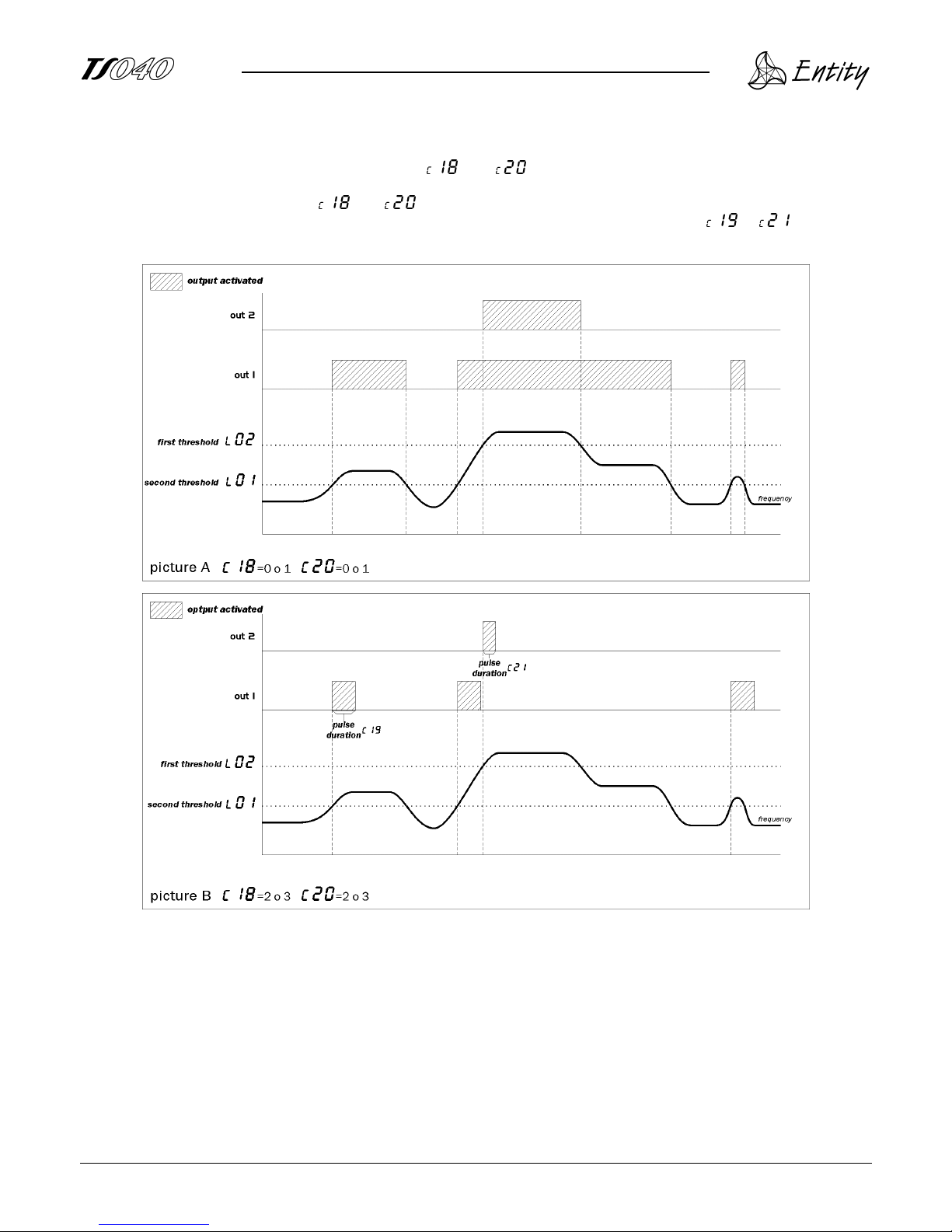
Outputs have positive or negative logic, as set in and . If these parameters values are 0 or 1, output is
activated as soon as measured value gets greater than set threshold and continues to be activated until the measured
value gets lower than it (pic. A); if and ’s values are set to 2 or 3, output will activate as soon as measured
value gets greater than set threshold, stays activated for as many seconds as they are set with or , and then it
is turned off even if measured value is still behind threshold one (pic. B).
Page 11
11
ERROR M E SSAGES
ERROR M E SSAGESERROR M E SSAGES
ERROR M E SSAGES
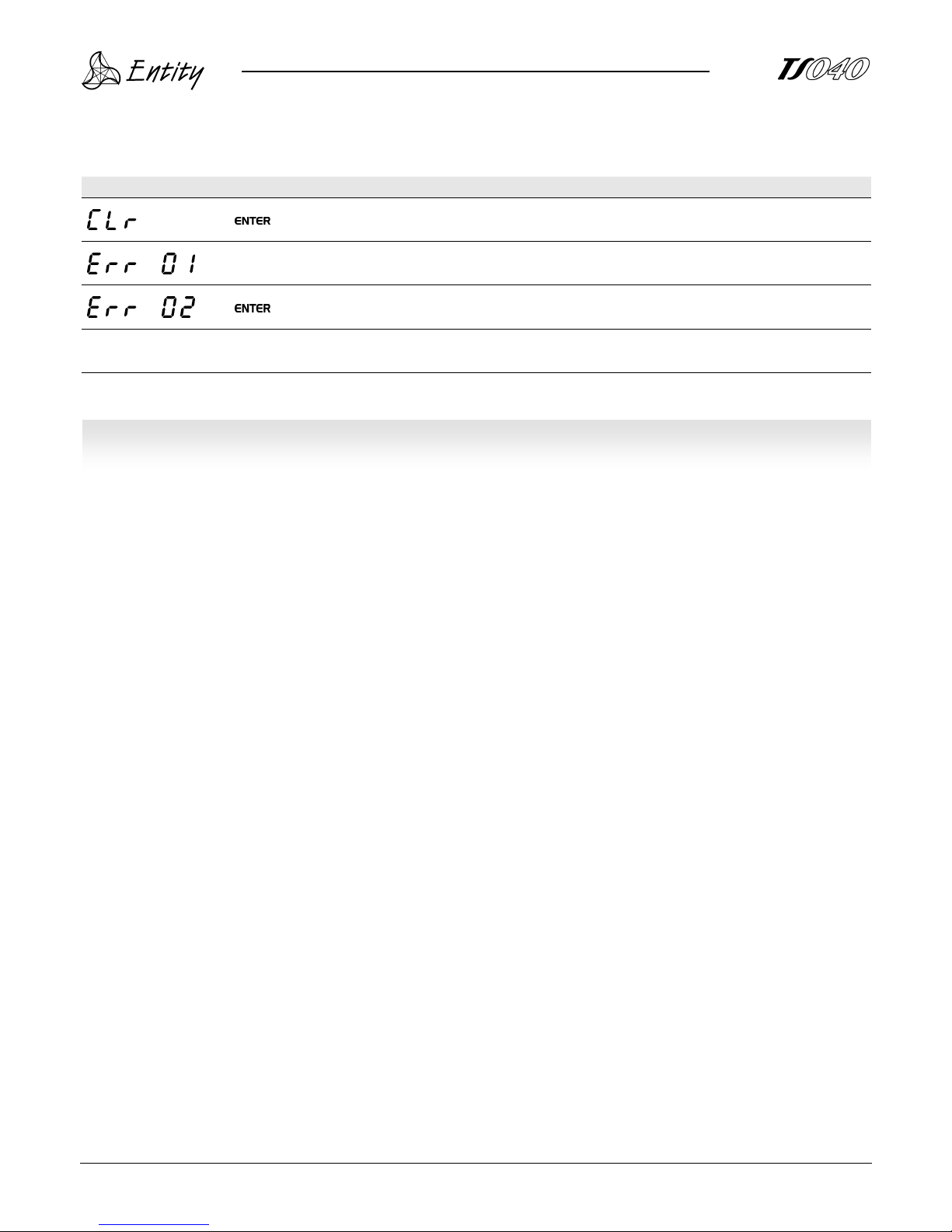
Error messages
Push and set parameters as has been explained above;
EEPROM failure; contact the device reseller;
Push and restore setup parameters as explained above;
Flashing display
measured value exceeds the maximum visualizable value.
WAR R A N T Y
WAR R A N T YWAR R A N T Y
WAR R A N T Y
The device is guarantee against construction vices or defected materials noticed within 12 months from delivery date;
The opening of the housing of the instrument, the wrong use and bad installation (due to non observance of the
indications of this manual) means the automatic decay of the warranty.
Page 12
12
Level visualizer
It shows single-axis level, with 6 digits visualization, relative counting and two memory records.
Frequency meter, speedometer
It shows level axis speed, compares it with two setpoints and provides two outputs signals.
Counter
It shows incremental counting, compares the value with two setpoints and provides two outputs
signals.
Single-axis positioner
It shows single-axis level, compares measured value with one setpoint and provides four output
signals.
The marking of single components does not assure that final product is compliant with the norm and does
not free the
producer from law duties on final product.
 Loading...