

Page 1
Page 2

P a g e | 2
AVM-T-MIX User Handbook Version Three
SAFETY
Installation.
Unless otherwise stated TSL equipment may be installed at any angle or position within an
-
All TSL equipment conforms to the EC Low Voltage Directive:
EC Low Voltage Directive (73/23/EEC)(OJ L76 26.3.73)(LVD).
Amendment: (93/68/EEC) (OJ L220 30.8.93).
In all cases the frame of the equipment must be earthed on installation.
Where appropriate, the earth pin on the IEC mains inlet connector is connected to the metal frame
of the equipment, to 0 volts on the internal DC PSU and to signal ground unless otherwise stated.
All metal panels are bonded together.
Check that the voltage selector setting (if fitted) and the fuse rating is correct for the local mains
supply.
Due consideration for cooling requirements must be given when mounting the equipment. It is
recommended that a 1RU of rack space, or a vent panel, should be left above and below the unit.
Page 3

P a g e | 3
AVM-T-MIX User Handbook Version Three
WARRANTY, MAINTENANCE AND REPAIR
All TSL products have a one year warranty period starting from the date it
leaves the factory.
A repair warranty is to apply. That is, the product is to be returned for
repair with no replacement and an exchange shipping policy is also to apply.
TSL offers a seven day DOA policy together with an exchange shipping
policy. That is, if a product has been declared ‘dead on arrival’ within a seven day period a
warranty replacement will be shipped.
A temporary replacement may be available where, for operational
reasons, it is imperative that service is continued. The customer will be asked to enter into
a ‘loan agreement’ for the duration of repair.
All faulty equipment returned to TSL for repair will, where possible, be
returned to the customer within seven working days.
TSL Returns Procedure
Please telephone +44 (0)1628 676221 (Fax: +44 (0)1682 676299) and ask for Customer
Support, detailing the model and serial number of the equipment, who will provide a Returns
Number. This will enable us to track the unit effectively and will provide some information prior to
the unit arriving.
For each item, this unique Returns Number must be included with the Fault Report sent
with the unit.
A contact name and telephone number are also required with the Fault Report sent with
the unit.
Fault report details required.
Company:
Name:
Address:
Contact Name:
Telephone number:
Fax number:
Email address:
Returns Number:
Symptoms of the fault (to include switch setting positions, input signals etc):
Packing
Please ensure that the unit is well packed as all mechanical damage is chargeable. TSL
recommends that you insure your equipment for transit damage.
The original packaging, when available, should always be used when returning equipment.
If returned equipment is received in a damaged condition, the damage should be
reported both to TSL and the carrier immediately.
Page 4

P a g e | 4
AVM-T-MIX User Handbook Version Three
This Page is Blank
Page 5

P a g e | 5
AVM-T-MIX User Handbook Version Three
Table of Contents
1.0 Introduction ............................................................................................................................ 7
1.1 Block Diagram ....................................................................................................................... 9
1.2 Operation ............................................................................................................................. 10
2.0 Controls and Displays - Overview ........................................................................................ 11
2.1 Source Selection .................................................................................................................. 14
2.2 Analogue Audio Input Trim .................................................................................................. 15
2.3 Channel Signal Format Selection – Stereo Mix/Mon Modes ............................................... 16
2.3.1 Stereo Channel Format: .............................................................................................. 16
2.3.2 Mono Channel Format: ................................................................................................ 16
2.3.3 Group Channel Format: ............................................................................................... 16
2.3.4 Group 2 PAIR ADD: ..................................................................................................... 16
2.3.5 Group 2 PAIR OFF: ..................................................................................................... 16
2.3.6 Group 5.1 DMIX: .......................................................................................................... 16
2.3.7 Group LRC DMIX:........................................................................................................ 17
2.4 Channel Signal Format Selection – Surround Sound Mix/Mon Modes ............................... 17
2.4.1 Stereo Channel Format: .............................................................................................. 17
2.4.2 Mono Channel Format: ................................................................................................ 17
2.4.3 Group Channel Format: ............................................................................................... 18
2.4.4 Group 5.1 ALL: ............................................................................................................ 18
2.5 Monitoring Input Channels – Solo Function ......................................................................... 19
2.6 Monitoring Input Channels – Mixer Function ....................................................................... 20
2.7 Audio Mixers 1 and 2 ........................................................................................................... 21
2.7.1 Switching Audio Mixer 1 to 5.1 mode .......................................................................... 21
2.8 Configuring and Naming Input Channels ............................................................................. 22
2.9 X-Y Routing ......................................................................................................................... 23
2.9.1 XY Routing Setup ........................................................................................................ 23
2.9.2 Internal Sources ........................................................................................................... 25
2.9.3 Physical Sources ......................................................................................................... 26
2.9.4 Choosing the active SDI input ..................................................................................... 26
2.9.5 Physical Outputs .......................................................................................................... 26
2.9.6 Routing Status ‘Window’ .............................................................................................. 27
2.9.7 Overview Menu Page .................................................................................................. 27
2.9.8 Conditional Routing Rules ........................................................................................... 28
2.9.9 Lock and Unlock Selection .......................................................................................... 28
2.9.10 Set as Default .............................................................................................................. 28
2.10 Routing System XY Crosspoint Map ................................................................................... 29
2.11 User Preset and Snapshot Management ............................................................................ 30
2.11.1 Home Button and User Presets ................................................................................... 30
2.11.2 User Presets – SAVE Menu ........................................................................................ 30
2.11.3 User Presets – Recall Menu ........................................................................................ 32
2.12 Setup Menu ......................................................................................................................... 33
2.12.1 Meter Menu .................................................................................................................. 33
2.12.2 dBFs Menu .................................................................................................................. 34
2.12.3 Meter Peak Menu ........................................................................................................ 34
2.12.4 Meter Zero Menu ......................................................................................................... 34
2.12.5 Meter Hold Menu ......................................................................................................... 35
2.12.6 SDI Input Select ........................................................................................................... 35
2.12.7 Mixer 1 Mode ............................................................................................................... 35
2.12.8 Output Menu ................................................................................................................ 35
2.13 Setup 2 Menu ...................................................................................................................... 36
2.13.1 User Save Menu .......................................................................................................... 36
2.13.2 Monitor Mode ............................................................................................................... 36
2.13.3 GPI Menu ..................................................................................................................... 37
2.13.4 Internal / External Loudspeaker Mute .......................................................................... 37
2.13.5 Surround Mix Menu ..................................................................................................... 38
2.14 Software Menu ..................................................................................................................... 38
3.0 Connectivity and pin-out details ........................................................................................... 40
3.1 Analogue XLR Connectors – Stereo Variable Output (Monitor Buss) ................................. 40
3.2 Analogue Output Connector ................................................................................................ 41
3.3 Analogue Input Connectors 1-4 and 5-8 – ........................................................................... 42
3.4 AES Input/Output Connectors 1-4 and 5-8 .......................................................................... 43
Page 6

P a g e | 6
AVM-T-MIX User Handbook Version Three
3.5 GPI Connector – HD15 Socket. ........................................................................................... 44
3.6 Remote Control Connector/ RS 422 - D9 Socket ................................................................ 44
3.7 DIP switch configuration functions – To be confirmed ........................................................ 44
4.0 Notes ................................................................................................................................... 45
4.1 General Notes...................................................................................................................... 46
5.0 AVM TOUCH SERIES - Technical Specifications ............................................................... 46
5.1 HD Standards Supported..................................................................................................... 47
5.2 Performance ........................................................................................................................ 47
6.0 Installed HDC-2T Audio Monitor Module Specification ........................................................ 48
6.1.1 Overview ...................................................................................................................... 48
6.1.2 Mechanical ................................................................................................................... 48
6.1.3 Power ........................................................................................................................... 48
6.1.4 Inputs ........................................................................................................................... 48
6.1.5 Outputs ........................................................................................................................ 48
6.1.6 Loudspeakers .............................................................................................................. 49
6.1.7 GPI inputs .................................................................................................................... 49
6.1.8 Control ......................................................................................................................... 49
Page 7

P a g e | 7
AVM-T-MIX User Handbook Version Three
1.0 Introduction
AVM-T-MIX is the world’s first rackmount Touchscreen controlled audio monitor unit. The TouchMix system delivers a unique combination of audio monitoring and channel mixing capabilities
designed to simplify operations and workflow throughout the Television broadcast environment.
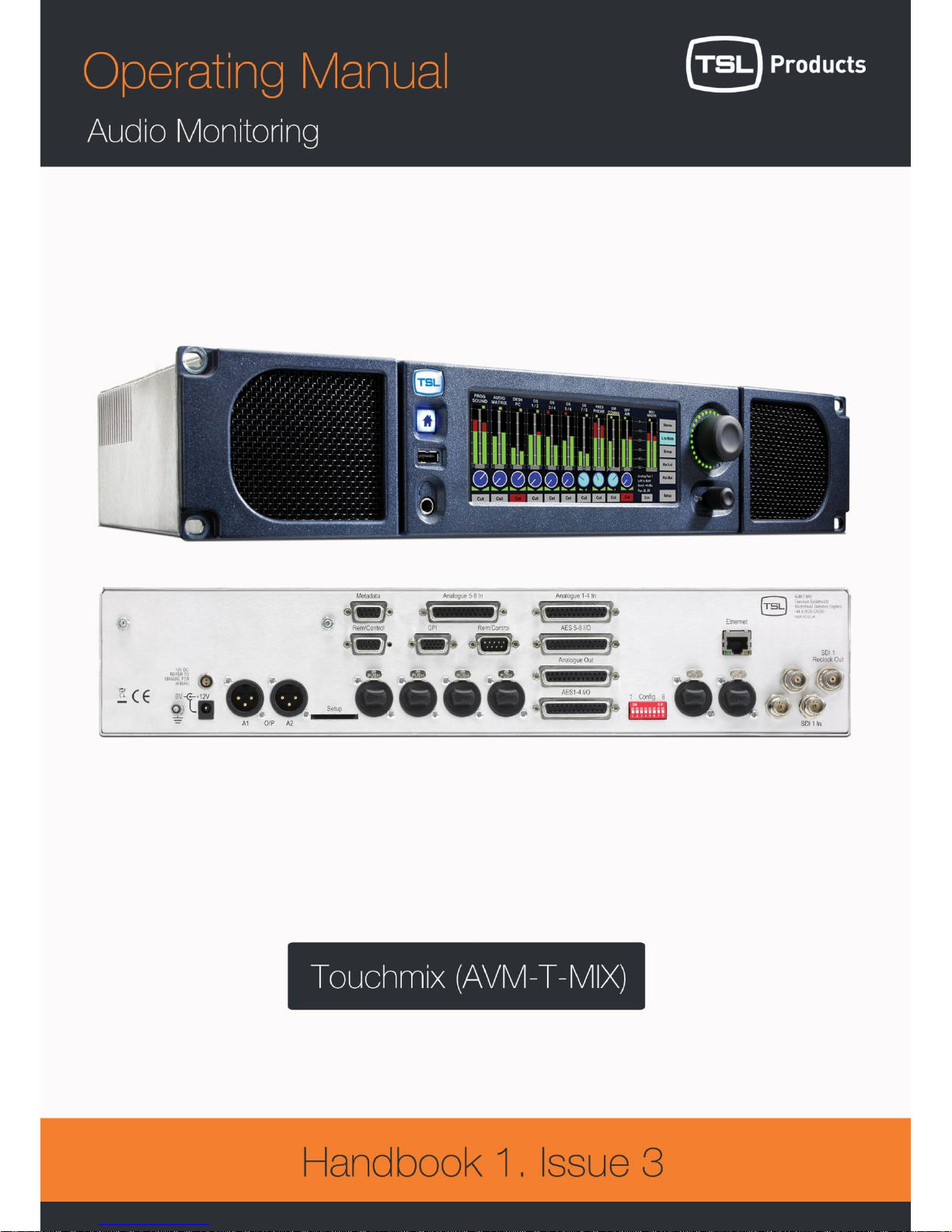
The AVM-T-MIX is a 2RU x 320mm Audio Mixer/Monitoring Unit controlled via a touch screen
interface and assignable hardware controls.
As with any new product which relies on complex software, it is possible that you may find minor
bugs or perhaps think of enhancements which would improve the operation of AVM-T-MIX. In the
event of either scenario, please feel free to contact TSL via your local reseller or directly on +44
1628-676221, asking for the TOUCH SERIES Product Manager.
TSL will be releasing upgrades and feature enhancements from time to time – as a purchaser of
AVM-T-MIX you should receive these directly, free of charge, through your reseller or directly from
TSL. Please refer to www.tslproducts.com for announcements.
The following features are standard:
Single or Dual (SD Only) Auto-sensing, 1080p (60, 59, 94 and 50Hz), HD/SDI video input
De-embedded audio monitoring from video (HD/SDI) with intuitive selection from up to
sixteen channels (SDI 1 only), and eight channels (SDI 2 Group 1 and 2 only)
8 AES (8 Pairs/16 Channel) and 4 AES (4 Pairs/8 Channel – SD Only) Inputs– 110Ohm
Balanced or 75 Ohm unbalanced via optional CAB-D25-BNC cable
8 Analogue Stereo Inputs
Identical twin audio mixers
10 stereo/ 20 dual mono assignable input channels per mixer
5.1 audio mixing and monitoring capability
Full input / output XY routing function
Surround Sound Speaker Output Support
Downmix of discrete multichannel audio to stereo for compatibility monitoring
Re-clocked HD/SDI video output.
Choice of user selectable bargraph scales (BBC PPM, EBU PPM, EBU Digital, Nordic, VU
and DIN)
18 User programmable presets.
‘Home’ button for instant recall of default operating condition
Manage, recall and save favourite configurations via USB stick or SD card
Fixed or variable analogue stereo outputs (mixer 1 and 2)
Fixed or variable AES stereo outputs (mixer 1 and 2)
Variable stereo analogue outputs (Monitor Buss)
High quality internal full range loudspeaker system
Dual 12V DC inputs
Serial remote control
Headphone output with LS muting
Compact, lightweight (5.1Kg) 2RU case, 320mm deep
Page 8
P a g e | 8
AVM-T-MIX User Handbook Version Three
Page 9
P a g e | 9
AVM-T-MIX User Handbook Version Three
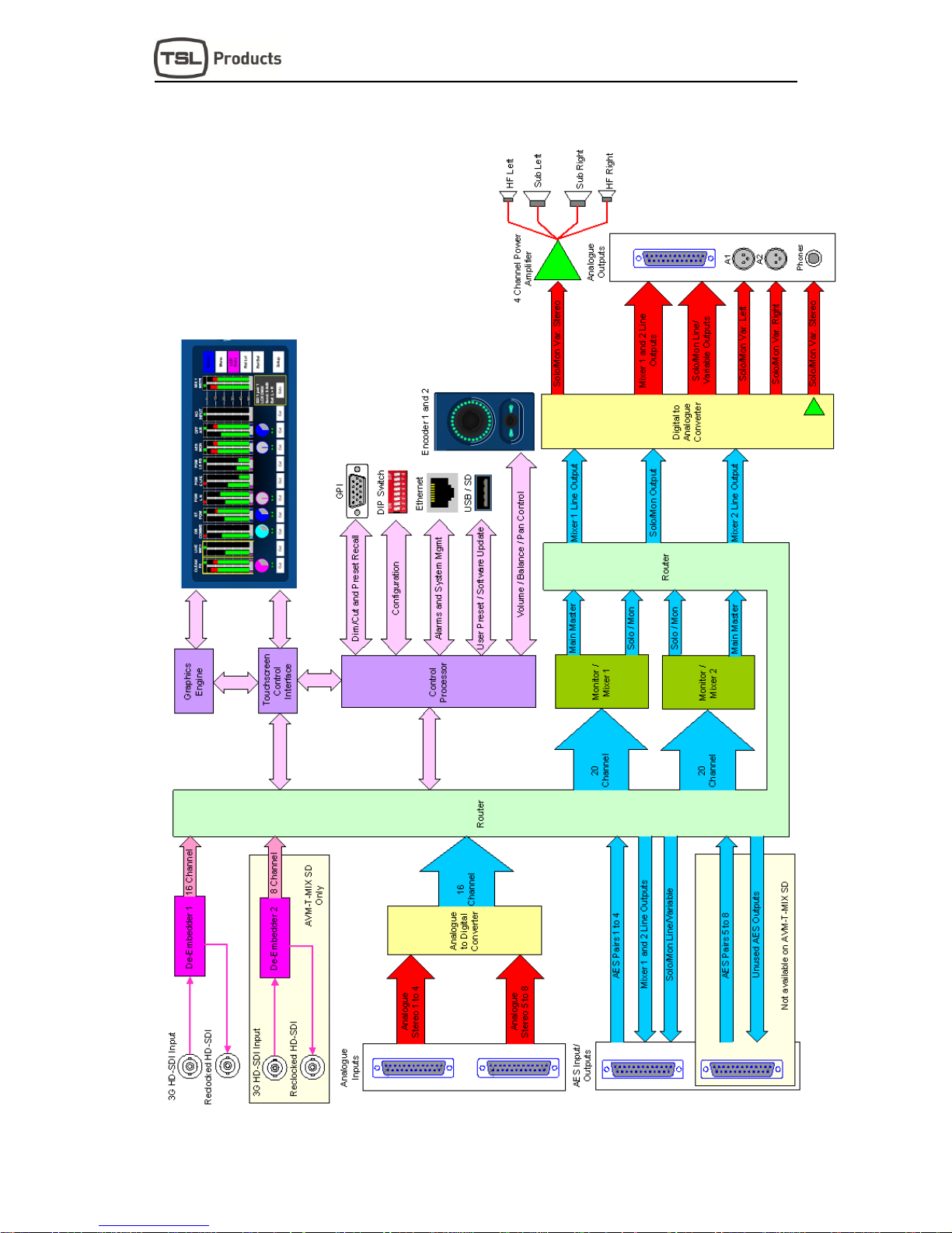
1.1 Block Diagram
Page 10

P a g e | 10
AVM-T-MIX User Handbook Version Three
1.2 Operation
The AVM-T-MIX is designed to be user friendly and intuitive to operate. The menus and functions
will feel familiar to both users of TSL multichannel audio monitoring products and those buying a
TSL solution for the first time.
Important Note: AVM-T-MIX ships with a default 0dBu reference level set to
-18 dBFS, the default operating scale is EBU Digital. The operational reference level for the
unit can easily be changed via the Setup menu (described elsewhere in this handbook).
Page 11
P a g e | 11
AVM-T-MIX User Handbook Version Three
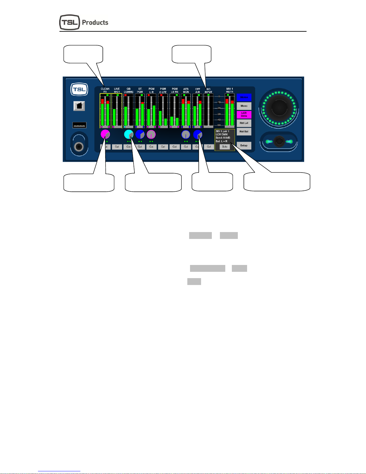
2.0 Controls and Displays - Overview
.
CLEAN
LCR
Dmix
Rst Lvl
Mono
Stereo
FX
LIVE
MIC1
OB
COMMS
PGM
L R
ST.
PGM
PGM
C LFE
PGM
LS RS
OFF
AIR
AES
MON
NO
INPUT
MSTR
0
10
20
30
40
50
Rst Bal
Setup
SDI 1 pair 1
Solo
LCR DMIX
Send: 0.0dB
Bal: L = R
MIX 1
Cut Cut Cut Cut Cut Cut
Cut
Cut Cut
Cut
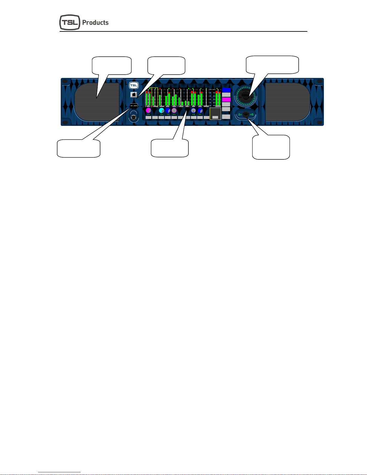
AVM-T-MIX is equipped with a 4 driver loudspeaker system comprising left/right tweeter
and dual subwoofer units.
Menus and features are navigated via the 22:9 aspect ratio touch screen.
The front panel USB connector is used for software upgrades; favourite user preset
storage and preset recall.
User presets can be recalled and stored locally using the ‘Home’ button.
Loudspeaker and headphone volume is adjusted by the master level control. This dual
action rotary encoder also features push to Cut/Dim functionality.
The dual function rotary encoder is rotated to control channel level ‘send’ with pan/balance
activated by push and turn.
Dual Action Monitoring
Level Control w/Cut, Dim
Dual Function
Encoder – Level
Send/Push for
Pan/Balance
4-Driver
Loudspeaker
System
USB Port for Field
Upgrades and
System Backup
‘Home’ Preset
Instant Recall
22:9 Aspect
Ratio LCD
Touch Screen
Page 12

P a g e | 12
AVM-T-MIX User Handbook Version Three
Touch and Hold channel bargraph to activate input selection menu.
Upon selection of input, selected channel format is selected via the Stereo/Mono/Group
buttons.
Selected channel gain and Bal/Pan level indicated by icons below bargraph display.
Stereo/Mono/Group channel format denoted by colour of level send control and ‘pips’
beneath bargraph pairs.
Individual channels can be ‘cut’ from main mix buss.
Individual channels can be ‘soloed’ to monitoring output buss.
AVM-T-MIX features two entirely independent Audio Mixers. Touch and Hold Mix Master
Bargraph to toggle between Mixer 1 and Mixer 2.
Mixer 1 can be configured for stereo and 5.1 outputs
Touch and Hold
Bargraph for
Source Selection
Input Channel
Format Selection
Level Send and
Bal/Pan
Indication
Selected Channel
Status and ‘Solo’
Button
Individual
Channel ‘Cut’
Switch
Stereo/Mono/Group
Channel Status
Touch and Hold Mix Master
Bargraph to Select Mix 1 or
Mix 2 Input configurations
Page 13
P a g e | 13
AVM-T-MIX User Handbook Version Three
Input sources named with a user defined 10 character mnemonic displayed above the
channel bargraph.
Unused input channels can be routed to ‘Silence’ displayed as ‘No Input’.
Channel Group format is denoted by use of Magenta or Yellow colouration.
Channel Group formats include ‘2 Pair’, ‘5.1 Downmix’, ‘LRC Downmix’ (as shown above)
and ‘5.1 ALL’.
Channel Stereo format is denoted by use of Electric Blue or Silver colouration.
Channel Mono format is denoted by use of Cyan colouration.
Channel Mono formats include ‘L+R, ‘Left to both’ and ‘Right to both’ (as shown above).
Selected Channel status shown in information ‘box’ includes ‘Source’, ‘Format’, ‘Send
level’ and ‘Bal/Pan adjustment’.
Input Channels
with 10 Character
User Mnemonic
Unused Input
Channels Routed
to ‘No Input’
Channels defined as
Group in either ‘2 Pair’,
‘5.1’ or ‘LRC’ formats
Channel defined as ‘Mono’,
‘Left Only’ or ‘Right Only’
formats
Channel defined
as Stereo format
Selected Channel overview
including ‘Input Source’,
‘Format’, ‘Send level’ and
Page 14
P a g e | 14
AVM-T-MIX User Handbook Version Three
2.1 Source Selection
Key to the ease of operation of AVM-T-MIX is the simplicity by which audio may be monitored
and/or mixed. As described previously, AVM-T-MIX is equipped with two completely independent
mixer/monitor systems (Mixer 1 and Mixer 2). Each can be configured with its own setup and used
in diverse applications.
Mixer 1 may be used as primary audio monitor in any application whilst the secondary mixer might
be used as a simple de-embedder to ‘back-feed’ another part of the system or even as a means to
derive a headphone cue to a voice over artist or commentator.
Setting up the monitor for use is simple and intuitive yet incredibly powerful.
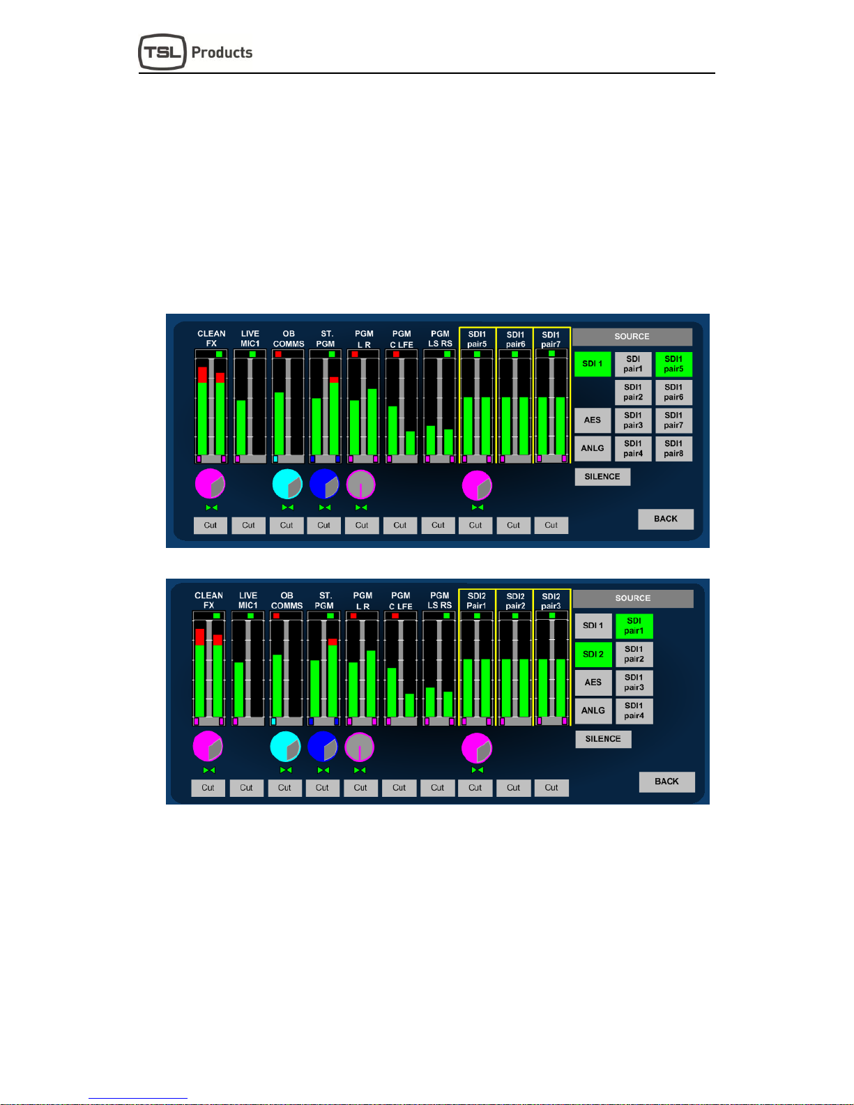
AVM-T-MIX Source Selection
AVM-T-MIX SD Source Selection
By simply touching and holding the desired channel the ‘SOURCE’ menu selection is
automatically activated. Select the signal type/pair or ‘SILENCE’ if no selection is required
and the chosen audio will be routed to the channel pair.
If the selected input has been configured with a User Name then the text string will be
displayed above the bargraph pair.
Audio is automatically routed to the selected channel from an active input and the signal
activity displayed on the bargraph. To hear the incoming audio instantly, simply press
SOLO and turn up the volume.
Touch ‘BACK’ to exit the ‘SOURCE’ menu.
Page 15
P a g e | 15
AVM-T-MIX User Handbook Version Three
2.2 Analogue Audio Input Trim
AVM-T-MIX is designed to be used with balanced or unbalanced analogue audio inputs. If one of
the analogue inputs has been wired to an unbalanced signal source then the user may need to
compensate for signal loss (typically -6dB). If this is the case then gain can be added to the chosen
analogue input in steps of 3dB by touching the button displayed below via the Setup/Input menu.
Please note that the AVM-T-MIX does not have an analogue signal amplifier and that the gain is
added in the digital domain. If gain is added to an unbalance analogue audio input in this way then
the signal to noise ratio of that signal will be affected accordingly and low level ‘hiss’ may be heard
in exceptional circumstances.
Press to access Input
Trim for low level or
unbalanced analogue
audio
Page 16

P a g e | 16
AVM-T-MIX User Handbook Version Three
2.3 Channel Signal Format Selection – Stereo Mix/Mon Modes
Applicable to Stereo Output Mixer Formats Only
Channel formats can be defined as Stereo,
Mono or a Group of 2 or more pairs (including
5.1 and LRC Downmix configurations).
2.3.1 Stereo Channel Format:
To define a channel as Stereo, simply touch the
desired bargraph pair followed by the ‘STEREO’
button from the Format menu (as shown).
The Level Send and format ‘Pips’ below the
bargraphs denote Stereo selection by the use of
Electric Blue colouration
2.3.2 Mono Channel Format:
To define a channel as Mono, simply touch the
desired bargraph pair followed by the ‘MONO’
button from the Format menu (as shown). The
MONO L/R menu is then activated enabling the
operator to choose between ‘Mono (L+R)’, ‘Left
(to Both)’ and ‘Right (to Both)’ formats.
Using the latest available software for the AVM-
T-MIX standard unit, only the chosen or
resultant audio bargraph is represented
The Level Send and format ‘Pips’ below the
bargraphs denote Mono format selection by the
use of Cyan colouration
2.3.3 Group Channel Format:
There are four modes of selection within the
GROUP menu designed to enable the user to
mix and monitor sources delivered in more
complex channel formats.
2.3.4 Group 2 PAIR ADD:
2 Pair Additive mode sums two adjacent stereo
audio pairs together in the format L+L and
R+R. The user can adjust the level of the left
sum against right via the balance control.
2.3.5 Group 2 PAIR OFF:
2 Pair Offset mode sums two adjacent stereo audio pairs together in the format L+L and
R+R however unlike the 2 PAIR ADD mode, the balance control is used to adjust the
relative mix of Pair One against Pair Two.
Pair Offset mode is particularly useful for adjusting the balance of monitored audio when
source material comprises a clean FX track on pair one and a commentary on pair two as
is often common in Sports Broadcasting.
2.3.6 Group 5.1 DMIX:
5.1 Downmix mode sums 3 adjacent pairs in an Lo Ro stereo format assuming that a
standard 5.1 configuration track order has been adhered to (L/R/C/LFE/Ls/Rs) as shown in
Page 17

P a g e | 17
AVM-T-MIX User Handbook Version Three
the image above. In 5.1 Downmix mode the LFE channel does not form part of the stereo
sum. The user can adjust the level of the left sum against right via the balance control.
The 5.1 Downmix algorithm follows the formula L+(C-3dB) + (Ls-3dB), R+(C-3dB) + (Rs-
3dB).
A user selectable adjustment located within the menu Setup/Setup2/DMIX enables
selection of the a ‘Surround -6dB) coefficient with the resultant formula
L+(C-3dB) + (Ls-6dB), R+(C-3dB) + (Rs-6dB) active depending on the selection.
2.3.7 Group LRC DMIX:
LRC Downmix mode sums 2 adjacent pairs together as a stereo signal with the first
channel of the second pair summed equally to the Left/Right channels. The user can adjust
the level of the left sum against right via the balance control.
The LRC Downmix algorithm follows the formula L+(C-3dB), R+(C-3dB)
The Level Send and format ‘Pips’ below the bargraphs denote a Group format selection by
the use of Magenta colouration
2.4 Channel Signal Format Selection – Surround Sound Mix/Mon Modes
Applicable to 5.1 Output Mixer Formats (see section 2.7.1)
When Mixer One is set to 5.1, additional channel format selections can be made in order to
route 5.1, stereo and mono signals to the appropriate surround sound output channels
2.4.1 Stereo Channel Format:
When operating with Mixer One set to 5.1, an
extended format selection option appears within
stereo channel format options. The operator
can choose by touch to route a stereo pair to
either the front or rear stereo left and right
channels
In the example shown you can see how SDI1
pair 9 is routed to the front left and right
channels and SDI pair 10 to the surround left
and right channels respectively. Front channel
routing is denoted by the Electric Blue or
colour and rear channel routing, by the Silver
colour.
2.4.2 Mono Channel Format:
When working on a 5.1 project a mono channel
selection enables the user to route mono audio
to anywhere across the image of the front
speakers (left, centre, right). This is achieved
using a divergence control that appears within a
mono mode adjacent to the left right panner.
In the example shown the mono channel
selection routes a chosen signal to the centre
mix channel only and the divergence (denoted
D:C) is highlighted in yellow and set to zero. By
pressing the encoder, the operator can toggle
between gain, pan and divergence controls
which can then be adjusted to vary the signal level sent to the centre, left and right
channels respectively thus providing complete control over the mono image across all
three channels.
Page 18

P a g e | 18
AVM-T-MIX User Handbook Version Three
2.4.3 Group Channel Format:
The four modes previously described for stereo mixer use (2 pair ADD, 2 pair OFF, 5.1
DMIX and LRC DMIX) remain active when a 5.1
mixer mode is activated however an additional
mode, 5.1 ALL, now appears under the
Grouping menu.
2.4.4 Group 5.1 ALL:
The 5.1 ALL mode is used to define a group of
signals that represent a 5.1 programme and
route them in order to the 5.1 mixer channel
output as shown in the image adjacent. A 5.1
ALL group when selected is represented by the
Yellow colour of the menu button and gain
control icon.
In this mode it is assumed that the audio
channels are presented in the order Left, Right, Centre, LFE, Left Surround, and Right
Surround and are routed to the mixer accordingly.
Page 19

P a g e | 19
AVM-T-MIX User Handbook Version Three
2.5 Monitoring Input Channels – Solo Function
Similar to a traditional rackmount audio monitoring unit, the AVM-T-MIX is used to listen to
incoming signal sources – either exclusively or additively. The simplest way to achieve this is to
touch the bargraph channel you wish to hear and then to select SOLO.
The selected signal will automatically be routed to the loudspeakers (internal or external) and to
the headphone socket.
The example above shows how an operator can quickly check an incoming Programme
audio signal which has been Downmixed to stereo from 5.1. In SOLO Mode. He/she
can now simply touch the adjacent 5.1 bargraph group labelled PGM2 in order to
compare the two signals or alternatively touch the SOLO buttons beneath another
bargraph pair to add the signals to the monitoring output.
The selected SOLO channels are automatically routed at unity gain to the output as
denoted by the position of the rotary SEND icon.
In SOLO mode, any MIXER routing configurations on either MIXER 1 or MIXER 2 are
unaffected.
When MIXER 1 is configured as 5.1 the SOLO function will automatically downmix any
selected channels to the internal stereo speakers or route a defined 5.1 channel group
to the 5.1 external speaker if used.
Page 20

P a g e | 20
AVM-T-MIX User Handbook Version Three
2.6 Monitoring Input Channels – Mixer Function
One of the unique advantages of AVM-T-MIX over a more traditional Audio Monitoring Unit is
the ability to mix sources together using the same methods found in assignable digital audio
mixing consoles. Mixer 1 and Mixer 2 are both equipped with main outputs which are routed to
the monitoring outputs (loudspeakers and headphones) and to fixed line level Analogue and
AES connections.
Individual bargraph channels can be mixed onto Master Output bargraphs by adjusting the send
level of the selected (highlighted by the yellow ‘box’) channel using the small rotary encoder
simply by turning it clockwise. By pushing and turning the encoder it is possible to adjust the
Balance (for Stereo and Downmixed sources) or Pan (Mono) of the selected output being sent
to the Mixer Master output.
The example above depicts a typical Lines Room application where the operator is
monitoring 3 different incoming language feeds as LRC Downmixes embedded within
the SDI infrastructure on channels 1 thru 6. He/She is simultaneously listening to audio
traffic via an AES router (channels 7 and 8) of Stereo Telco feeds 1 and 2 from another
location plus a mix of local and remote mono Talkback on channels 9 and 10.
The Talkback inputs from the Outside Broadcast and local Studio are panned to the
left and right channels respectively to give separation against the Clean/Native
Language Downmix coming from the OB event.
Channels 3 and 4 plus channels 5 and 6 contain Clean/Alternative Language
Downmixes which are being generated locally from Voice Over Booths with French
and German Commentators.
Mixer 2 line level outputs can be used in this application to provide a Submix of the
Clean International Audio plus Local and OB Talkback to the Commentators via their
local headphone amplifiers.
Mixer 1 can be configured to operate in 5.1 mode. When selected via the setup menu
Setup/Mixer/Surround the main output of Mixer 1 comprises a full 5.1 buss structure
of Left/Right/Centre/LFE/Left Surround/Right Surround that can be used for
external monitoring (via externally connected surround sound speakers) and also
delivers a fixed level 5.1 mixer output to both analogue and AES output connections
Even when Mixer 1 is configured for 5.1 use a parallel stereo version of the mixer runs
as a background application and can be used as an alternative auto-downmixed output
or for stereo monitoring (including internal and headphone outputs on the T-MIX itself).
Page 21

P a g e | 21
AVM-T-MIX User Handbook Version Three
2.7 Audio Mixers 1 and 2
The AVM-T-MIX is equipped with two identical but independent 20 channel (10 stereo bargraph)
audio mixers designed to enable the operator to create their own custom monitoring setups.
On first power up, AVM-T-MIX displays the bargraphs associated with Mixer 1 as denoted by the
mnemonic MIX 1 MASTER above the output bargraph pair as shown below.
Simply touching the Mix Master 1 bargraph for a few seconds will toggle the display between
Mixer 1 and Mixer 2; each mixer can be configured entirely independently as described in the
following sections of this Handbook by simply touching and holding any of the 10 bargraph pairs.
2.7.1 Switching Audio Mixer 1 to 5.1 mode
Mixer 1 can be set to operate in surround 5.1 mode by entering Setup from the top level screen,
chose Mixer and then Surround. The L/R/C/LFE/Ls/Rs channel bargraph view appears
automatically in place of the stereo output bargraph.
Note: If you configure the T-MIX for 5.1 operation when Mixer 1 is in surround mode and
then switch to stereo, the 5.1 configuration will be remembered and recalled when you
switch back. This feature can be useful when checking stereo compatibility of a 5.1 project
mix.
Example: The image
represents a configuration
used by a current T-MIX
customer who uses the 5.1
monitoring capability in a
Post Production facility
working in conjunction with
their Avid Edit platform
The timeline of their typical project comprises a compiled 5.1 programme audio stem (pairs
1, 2 and 3) plus the individual elements of the 5.1 mix (pairs 4, 5, 6 and 7) which includes
stereo Lt Rt, mix and effects plus mono dialogue channels.
The T-MIX configuration enables the operator to listen to individual channel elements,
adjust their gain within the mix and compare to the compiled 5.1 mix. Connectivity with the
Avid system is via SDI from the edit break out box (BOB) but could equally be achieved
using AES or analogue connections.
Initial Power Up:
Mixer 1 Input and
Output Channels
Page 22

P a g e | 22
AVM-T-MIX User Handbook Version Three
2.8 Configuring and Naming Input Channels
The physical audio connections into AVM-T-MIX comprise of 16 channels from HD-SDI (16
channels SDI 1, 8 channels SDI 2)), 8 AES pairs and 16 (or 8 stereo) analogue audio inputs. Each
pair can be routed to any of the 10 channel bargraphs available to either Mixer 1 or Mixer 2 and to
simplify operation, each input pair can be given a User Name.
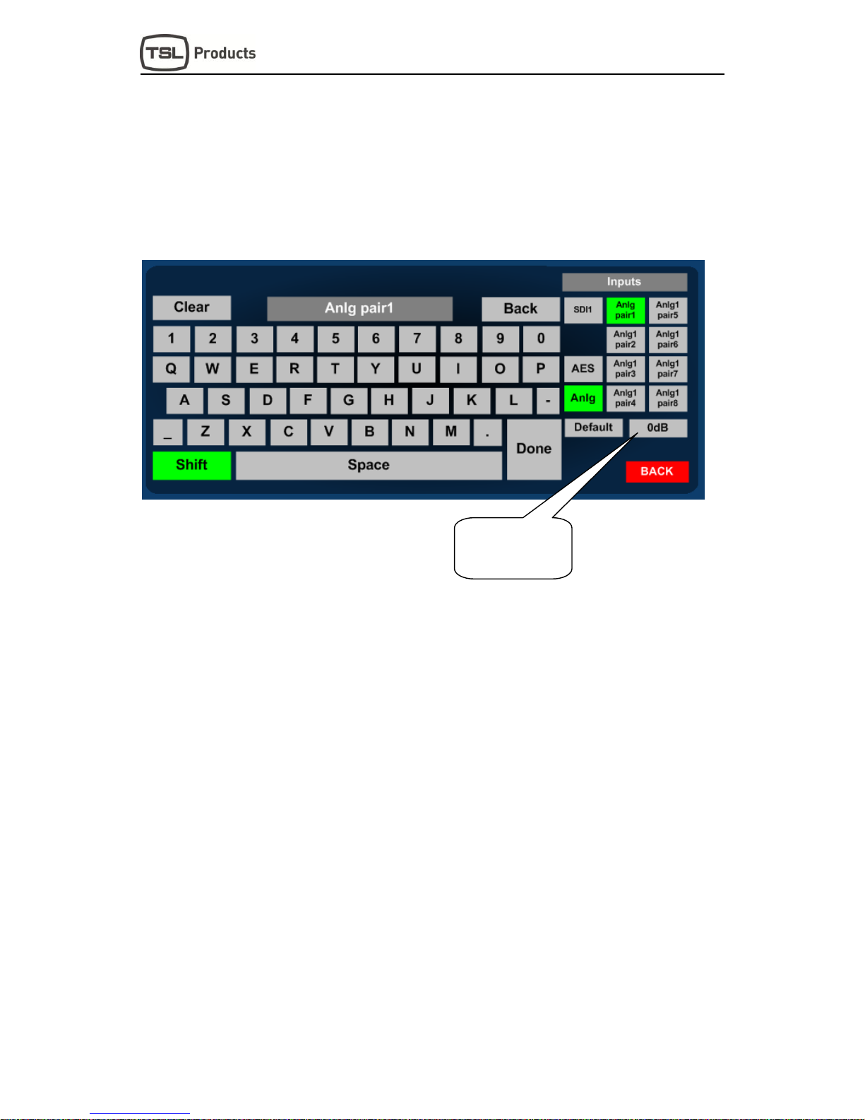
In order to simplify the naming of input sources the AVM-T-MIX is equipped with an onscreen
QWERTY style keyboard which can be accessed via the Setup/Input menu page.
To apply a name to an input source simply select the appropriate pair, press CLEAR to
delete the default name and enter the chosen replacement in the dark grey field. Press
DONE when complete.
User names can be up to 10 characters long and can consist of upper/lower case letters,
numbers and a very limited set of symbols ‘-‘ ‘_’ and ‘.’
When entering a text string AVM-T-MIX will automatically enter a space between the 5th
and 6th characters unless the user inserts a space at any other point within the name.
When a signal with an associated User name is routed to a channel bargraph, the name is
displayed above the bargraph in two rows of text with up to 5 characters in each.
Page 23

P a g e | 23
AVM-T-MIX User Handbook Version Three
2.9 X-Y Routing
The XY router gives the user complete control over source to destination configuration.
Any physical input or buss (mixer, monitor) can be assigned to any AES or analogue
output connector
The XY router allows the user to create different configurations for each User Preset
enabling them to tailor connectivity to suit different project workflows and recall them when
needed.
The XY router can split the left and right components of any external audio source and
route them independently to the chosen destinations.
Any routing created within the XY router can be copied as a ‘default’ from the Overview
page to the all user presets. For example; the user may be setting up a room with 5.1
speakers wired to analog outputs 1 to 6. After creating this route within the XY system, the
user can then enter the Overview page, select Analog Pair 1,2,3 outputs and press ‘Set as
Default’. When selected, the default condition will be written automatically to all 18 User
Presets.
Unlike previous versions of T-MIX, the user is now able to select which of the SDI BNC
connecters (SDI 1A or SDI 1B) is routed to the single de-embedder and made available to
the mixer and router. This initial releases of T-MIX code XY identifies the BNC’s labelled
on the rear panels as SDI 1 and SDI 2 and refers to them in the menu as SDI 1A and SDI
1B respectively. This is to avoid confusion with the options AVM-T-MIX 2SD model which
features a second de-embedder card and an additional BNC connection.
2.9.1 XY Routing Setup
The XY router is found via the setup menu by pressing Setup>Output.
The router is divided into two parts, Source and Output and can be used to assign any physical
input (SDI, AES and analogue) and internal source (Mixer 1, Mixer 2 and Monitor) to any of the
physical output ports.
Page 24

P a g e | 24
AVM-T-MIX User Handbook Version Three
Routing selection must always be performed in the order Select Output > Select Source > Take.
By default any routing assignment is made in stereo however it is possible to route left or right
signals independently using the following sequence Select Output > Select Out Left or Out
Right > Select Source > Select Left Only or Right Only > Take
The default routing is described below: It is repeated for each of the 18 user presets and also the
Home setting. Any changes made to routing will be made from within a preset and must be saved
in order to be recalled as they would within a large audio console.
D25 Connectors
Anlg 1 Out = Mixer 1
Anlg 2 Out = Mixer 2
Anlg 3 Out = 2.0 Fixed Monitor
Anlg 4 Out = 2.0 Variable Monitor
AES 1 Out = Mixer 1
AES 2 Out = Mixer 2
AES 3 Out = 2.0 Fixed Monitor
AES 4 Out = 2.0 Variable Monitor
AES 5 Out = Silence
AES 6 Out = Silence
AES 7 Out = Silence
AES 8 Out = Silence
Analogue XLR Output Connectors
Analogue Out = 2.0 Variable Monitor
If you choose to connect analogue input based surround sound speakers to the Touchmix it will be
necessary to route 5.1 Variable sources to Analogue pair 1, 2 & 3 connections.
Page 25

P a g e | 25
AVM-T-MIX User Handbook Version Three
2.9.2 Internal Sources
An AVM-T-MIX Internal Source may be thought of as a type of router input that is derived within the
mixer rather than a physical connection.
The Internal Source list within the Touchmix includes the following;
Mixer 1 – Stereo Mixer One. When 5.1 ALL is activated, Stereo Mixer One will always carry a
downmixed version of the surround sound mix output.
Mixer 2 – Stereo Mixer Two
Mon Fixed – The stereo fixed line level audio representation of what is heard by the operator when
using the Touchmix. This could be either Mixer or Solo (when activated)
Mon Var - The stereo variable, line level audio representation of what is heard by the operator
when using the Touchmix. This could be either of the mixers or Solo (when activated) and is
typically the signal heard in either the internal speakers or headphones or connected to external
stereo speakers.
5.1 Fixed – The 5.1 fixed line level audio representation of what is heard by the operator when
using the Touchmix with 5.1 ALL activated.
5.1 Var - The 5.1 variable, line level audio representation of what is heard by the operator when
using the Touchmix with 5.1 ALL activated.
Silence – Routes Silence to a chosen output
Note: Internal Sources cannot be split into mono parts
Page 26

P a g e | 26
AVM-T-MIX User Handbook Version Three
2.9.3 Physical Sources
Touchmix has a total of 64 available physical sources available taken from SDI, AES and Analog
connections, of which 48 are available at any given time. Each pair can be selected as a stereo or
left only, right only input and routed to any physical output using the routing procedure described
later in this document.
2.9.4 Choosing the active SDI input
In previous versions of the Touchmix SD operating system the user could only access one of the
physical SDI connectors and hence only a single video source could be wired to the box. In the
latest release (from June 2014 onwards) the user is given access to an onboard 2x1 SDI switch
and can choose to de-embed either of the physical SDI ports.
An additional menu has been added to the product to enable this exclusive selection and can be
accessed via the following commands Setup>SDI> SDI 1A or SDI 1B
The selected SDI input chooses between physical BNC inputs labelled SDI 1 and SDI 2 however to
avoid confusion with the AVM-T-MIX 2SD product, the menu refers to the inputs as SDI 1A and 1B.
Which input is chosen will be routed to the de-embedder and therefore available to the routing
system exclusively for any given User Preset.
2.9.5 Physical Outputs
As previously described in an earlier section regarding the default routing setup, the Touchmix
comprises a total of 26 physical output ports. 16 AES channels (8 pairs) are presented on two D25
connectors, 8 analog channels are presented on a further D25 connector and an additional analog
pair appears on two XLRs.
Page 27

P a g e | 27
AVM-T-MIX User Handbook Version Three
2.9.6 Routing Status ‘Window’
The text box in the centre of the AVM-T-MIX is a Routing Status indicator which provides a brief
information summary of the highlighted route. The Routing Status Window indicates five fields of
useful data;
Output – physical output pair
Input – physical or internal source
Preset – current active User Preset
Lock Status – Route is locked or unlocked
Signal Pass – Output will pass audio, data, Dolby or all formats
The image below shows the Routing Status Window in the centre of the output screen where the
5.1 Variable buss has been assigned to analogue output pairs 1, 2 and 3.
The User Preset is in this example is called ‘Saturday Sport’; the route is ‘Locked’ to prevent
accidental re-assignment and the only signal format permissible is audio so that the surround
speakers wired to the outputs are protected from data signals such as Dolby E.
2.9.7 Overview Menu Page
The Overview Page is reached via the following path Setup>Output>Overview
It comprises an XY routing system overview matrix as well as several command buttons that are
used to set routing rules, default conditions and to lock routing selections to prevent misuse.
Overview Table – The overview table gives the user a visual summary of the current routing
status of either the AES or Analog output routing status.
By touching a pair or group of output channels on the overview table will display the system
settings at the right hand side of the screen.
Page 28

P a g e | 28
AVM-T-MIX User Handbook Version Three
The upper line of text in each ‘button’ shows the physical output connection and the lower line
shows the currently routed source.
2.9.8 Conditional Routing Rules
The user can choose from the Overview Page the way that the selected output manages particular
types of audio. By default the Touchmix is designed to mute all non-PCM Audio signals to prevent
data (such as non-decoded Dolby E) from being accidentally routed to a loudspeaker. Using the
conditional routing rules, any type of signal can be passed from source to destination without being
muted.
2.9.9 Lock and Unlock Selection
Once a critical routing selection has been made such as the assignment of 5.1 or Stereo variable
monitoring to a pair of speakers via an analogue connection, the operator can lock the route to
prevent accidental changes. The example shows a 5.1 Variable output that has been routed to
analogue pairs 1,2,3 and locked to prevent re-assignment in error
2.9.10 Set as Default
Routing selections such as the assignment of 5.1 or Stereo Variable outputs to external
loudspeakers are usually part of an installation and not changed once the Touchmix has been
cabled. ‘Set as Default’ enables the operator or technician to configure any Analogue or AES
routing assignment from a single preset and then automatically copy the highlighted settings to all
other user presets.
The example below shows a 5.1 Var speaker assignment being set as a default to all 18 user
presets. The routing assignments to Analogue 4L/R and the XLR connectors would not be written
to all other presets as they are not highlighted. To set further default settings each group or pair to
be set must be actioned in turn.
Page 29

P a g e | 29
AVM-T-MIX User Handbook Version Three
2.10 Routing System XY Crosspoint Map
The matrix below describes the components of the XY routing system as a crosspoint map with the
input sources to the Y Axis and the outputs to the X Axis. The right hand block of blue crosspoints
denotes the bargraph routing selection to the mixers 1 and 2 and their resultant mix and monitor
outputs can be seen towards the bottom left represented as routable sources.
Although the majority of the routing infrastructure is freely assignable, you can see from the way
that the 5.1 Mixer and Monitor busses are grouped that these sources can only be assigned to the
first three pairs of any output AES or Analog output connector. This is one of very few restrictions
imposed by the XY router system along with the fixed assignment of the stereo monitoring busses
to the headphones and internal speakers.
Page 30

P a g e | 30
AVM-T-MIX User Handbook Version Three
2.11 User Preset and Snapshot Management
2.11.1 Home Button and User Presets
AVM-T-MIX uses both internal and external User Preset memories to enhance usability, there are
a total of 18 User Presets in local memory plus a Snapshot which is defined as HOME enabling
operators to instantly revert to a default operational condition.
A User Preset is defined as a Snapshot of a state of operation and includes the following
parameters;
MIXER 1 and MIXER 2
System XY Routing Configuration
Channel Source Selection
Channel Output ‘Send’ Levels
Channel Pan/Balance
Channel Format Selection
Input User Names
Bargraph Configuration (including Scale, Ref, Zero etc.)
GPI Mode
Internal LS Mute Status
External LS Mute Status
Surround Mix Coefficient
User Preset Name
AVM-T-MIX total of 18 Internal Memories can be backed up to a USB memory stick (front panel
port) or SD Card (rear panel slot). Access to the USER PRESET/HOME menus is via the front
panel HOME button.
2.11.2 User Presets – SAVE Menu
Holding down the HOME button for approximately 3 seconds accesses the SAVE menu. This
menu page allows the operator to create and save snapshot memories, to backup the onboard
memories to an external device or to configure the HOME preset.
Set Home – Pressing the Set Home button will automatically store the current operational
configuration to the Home snapshot location.
Page 31

P a g e | 31
AVM-T-MIX User Handbook Version Three
Set User – Pressing the Set User button enables the operator to store the current operational
configuration to any of the 18 internal memory locations. The following menu will appear;
Simply select the desired internal memory location (User 1-18), enter a name using the QWERTY
keyboard (press Clear to remove the default name) and Save to store.
USB Save
Pressing the USB Save button (only active when a USB Stick is inserted) enables the operator to
backup all 18 internal memories to an external memory device. If an SD card is used via the rear
panel then the AVM-T-MIX will save to that device. If both a USB and an SD device are inserted
simultaneously, the USB location will take precedence. The USB Save menu will ask the operator
to confirm if they wish to replace an existing memory file before completing a backup.
Page 32

P a g e | 32
AVM-T-MIX User Handbook Version Three
2.11.3 User Presets – Recall Menu
Pressing the HOME button momentarily accesses the Recall menu. This menu page allows the
operator to recall saved snapshot memories, to recall memories from an external device and to
instantly recall the HOME snapshot.
Recall Home – Pressing the Recall button will automatically load the stored Home snapshot from
internal memory. If no Home snapshot has been stored, the default shipping condition will be
reloaded.
Get User – Pressing the Get User button enables the operator to load any of the 18 internal user
presets from memory. User Presets are displayed in groups of 6, pages 1 to 3 are recalled via the
More … button.
USB Load – Pressing the USB Load button (only active when a USB Stick is inserted) enables the
operator to restore all 18 internal memories from an external memory device.
Page 33

P a g e | 33
AVM-T-MIX User Handbook Version Three
2.12 Setup Menu
Setup Menu includes options for different Scales, Reference Levels, Peak Hold, Input Naming,
Output Routing, SDI Input Select, Mixer 1 mode and access to the Setup 2 Menu. By simply
touching the appropriate button, individual sub menus are selected.
2.12.1 Meter Menu
Pressing the Meter button accesses the bargraph scale options. AVM-T-MIX is able to accurately
replicate EBU Digital, EBU PPM, BBC PPM, DIN PPM, Nordic PPM and VU scales and ballistics.
Please note that the selection of a scale type within the Meter screen will only be remembered by
AVM-T-MIX as a preset once the selection has been saved to internal memory using the User
Preset commands described previously. This restriction enables the user to save preset conditions
which work using different bargraph scales.
Page 34

P a g e | 34
AVM-T-MIX User Handbook Version Three
2.12.2 dBFs Menu
The dBFs parameter selection can be used to alter the 0dBu reference level from between -12 and
-24 dBFs.
2.12.3 Meter Peak Menu
The Peak parameter selects the offset level between the Reference dBFS setting and the onset of
Peak indication (the point where the bargraph changes colour to red) from between +1dB and
+18dB.
2.12.4 Meter Zero Menu
The Meter Peak selects between two modes of peak indication displayed on the channel
bargraphs. The Bar Mode illuminates the bargraph as red once the audio level exceeds the peak
value. In Block Mode the bargraph illuminates in yellow when the audio level exceeds the
reference value and then red when it exceeds peak (as illustrated below).
Page 35

P a g e | 35
AVM-T-MIX User Handbook Version Three
2.12.5 Meter Hold Menu
AVM-T-MIX features a simple Peak Hold indicator which may be turned on and off using the Meter
Hold Menu.
2.12.6 SDI Input Select
A standard AVM-T-MIX has two SDI inputs that can be switched into a single de-embedder as
illustrated by the block diagram towards the front of this handbook.
The screen printing on the rear of your AVM-T-MIX is likely to denote the two SDI inputs as SDI1
and SDI2 respectively however the menu refers to them as SDI1A and SDI1B in order to
differentiate between single and dual de-embedder product versions.
2.12.7 Mixer 1 Mode
As previously described, Mixer 1 can operate in either Stereo or 5.1 modes. The mixer can be
switched via the illustrated menu above.
2.12.8 Output Menu
The function of the Router Output menu is described elsewhere in this handbook
Page 36

P a g e | 36
AVM-T-MIX User Handbook Version Three
2.13 Setup 2 Menu
Setup 2 Menu includes options to protect User Presets, GPI Action, External and Internal
Loudspeaker Mute, Surround Downmix Coefficients, Monitor Mode and to access the
Software Management Menu.
2.13.1 User Save Menu
The User Save Menu enables an Engineer or Technician to Lock or Unlock the User Preset
management system onboard AVM-T-MIX. In Locked mode a user is able to recall the Home
Preset but unable to save or recall memories from internal or external (USB or SD Card) locations.
2.13.2 Monitor Mode
The Monitor Mode Menu is used to select the audio sent to the internal speakers and headphone
socket when T-MIX is not in Solo listening mode.
Page 37

P a g e | 37
AVM-T-MIX User Handbook Version Three
In Default mode the operator would normally hear the output of whichever mixer is currently shown
on the touchscreen. The user can choose to hear either Mixer 1 or Mixer 2 permanently
regardless of the mixer under direct control.
2.13.3 GPI Menu
The GPI Menu enables an Engineer or Technician to select whether GPI inputs respond to
Latching or Momentary closures from external devices. The GPI connector can be used to Cut/Dim
the internal and external Loudspeakers, recall Home preset and to recall User presets 1 to 7. The
pin-out is described in Section 3.5.
In Momentary Mode, Dim and Cut GPI's latch in a toggle manner, i.e. one closure to ground
toggles the function ON; the next ground toggles it OFF. In an ON state; the GPI pin is driven low
to allow an LED to be fed from the port. This LED drive is briefly pulsed high at about 100Hz to
allow the port to be read whilst it is driving.
The preset recall GPI’s in ‘Latching’ mode are mutually exclusive.
2.13.4 Internal / External Loudspeaker Mute
The AVM-T-MIX is designed to be used with either Internal or External Loudspeaker Systems.
Users may wish to define User Preset conditions which associate the operation of the unit with
internal speakers for in one state and external speakers in another. To facilitate this kind of hybrid
operation the AVM-T-MIX is equipped with individual Loudspeaker Mute buttons which can be
configured with different functionality dependant upon their desired use and then saved to
individual presets.
In the event that AVM-T-MIX is installed for use with external speakers only with the intention to
mute the internal speakers, a DIP switch on the rear panel can be used to override the Internal LS
Mute button in Setup 2 Menu.
Page 38

P a g e | 38
AVM-T-MIX User Handbook Version Three
2.13.5 Surround Mix Menu
The S-MIX Menu provides a means to select the Downmix coefficient by which the Rear Surround
Loudspeaker audio channels are added to the Front Left and Right when a Group/5.1 DMIX
mode is selected.
When -3dB is selected, the 5.1 DMIX feature creates a stereo fold-down of the 5.1 channels using
the following algorithm;
L= L + (Ls -3dB) + (C -3dB); R= R + (Rs -3dB) + (C -3dB)
When -6dB is selected, the 5.1 DMIX feature creates a stereo fold-down of the 5.1 channels using
the following algorithm;
L= L + (Ls -6dB) + (C -3dB); R= R + (Rs -6dB) + (C -3dB)
2.14 Software Menu
TSL is committed to providing customers with free life of product software updates as the features
of AVM-T-MIX evolve and any bugs are addressed. New code is made available via our reseller
distribution channels and as a download from the TSL website.
http://www.tsl.co.uk/support_updatedapps.aspx.
System Software may be updated by the owner via either the front panel USB Port (using a USB
memory stick) or the rear panel SD Slot. Accessing the path Setup/ Setup2/ SWare the AVM-T-
MIX will enter a menu page which reports the current software versions of the onboard Front Panel
driver board (FP4), FPGA and PIC devices on the upper three information fields. If a memory
device is inserted containing a software revision the three update fields will be displayed as
illustrated below;
Page 39

P a g e | 39
AVM-T-MIX User Handbook Version Three
In order to commence the upload sequence, simply press the UPDATE button and the FP4, FPGA,
and PIC code will be loaded in order. Progress in indicated via the 0-100% scale.
Once complete, AVM-T-MIX will display a message confirming that the process has been
successfully concluded prompting the user to perform a factory reset. To perform a factory reset it
is necessary to remove power from the unit and then re-apply power whilst pressing the Home
button until a message appears to confirm that Factory Default has been reloaded. Press Home
once more and you will be able to operate AVM-T-MIX with the new firmware active.
The action of restoring Factory Default status will remove any stored memories from the
AVM-T-MIX. Please backup and restore memories from an external device if required.
Please note that the UPGRADE sequence may take several minutes and may appear to
‘stall’ – it is important not to interrupt the process or to remove power from the device
during a software upload as this may render the AMU unusable.
Page 40

P a g e | 40
AVM-T-MIX User Handbook Version Three
3.0 Connectivity and pin-out details
AVM-T-MIX uses industry standard connectivity wherever possible. The D25 connectivity used for
analogue and AES I/O adopts a pinning convention commonly used for Yamaha Commercial Audio
equipment and breakout cables are readily available at low cost from companies such as
www.cpc.farnell.com www.hosatech.com and many others.
For unbalanced AES I/O connectivity an optional BNC breakout cable, CAB-D25-BNC, is available
from TSL or your local reseller. When used in conjunction with AVM-T-MIX, DIP switch 2 (AES
Impedance) must be switched to the 75 ohm position.
PLEASE NOTE THAT THE CONNECTIVITY INFORMATION PERTAINING TO ANALOGUE AND
AES IN/OUT REFERS TO ‘AS SHIPPED’ SYSTEM DEFAULTS. USING XY ROUTING
FUNCTIONALITY IT IS POSSIBLE TO RECONFIGURE THE OUTPUT CONNECTIONS TO SUIT
ANY USER PREFERENCE – ALL PINOUT INFORMATION REMAINS THE SAME
3.1 Analogue XLR Connectors – Stereo Variable Output (Monitor Buss)
CONN
PIN
FUNCTION
ANALOG 1
1
GND
ANALOG 1
2
1 IN+
ANALOG 1
3
1 IN-
ANALOG 2
1
GND
ANALOG 2
2
2 IN+
ANALOG 2
3
2 IN-
Page 41

P a g e | 41
AVM-T-MIX User Handbook Version Three
3.2 Analogue Output Connector
D25 Socket Pinout on unit, Plug (shown) on mating cable.
D 25 SOCKET
ON AMU
AUDIO OUT
PIN NO
FUNCTION
1
A8+ (Var. Mon R)
14
A8- (Var. Mon R)
2
Ground
15
A7+ (Var. Mon L)
3
A7- (Var. Mon L)
16
Ground
4
A6+ (Fixed Mon R)
17
A6- (Fixed Mon R)
5
Ground
18
A5+ (Fixed Mon L)
6
A5- (Fixed Mon L)
19
Ground
7
A4+ (Fixed Mix 2R)
20
A4- (Fixed Mix 2R)
8
Ground
21
A3+ (Fixed Mix 2L)
9
A3- (Fixed Mix 2L)
22
Ground
10
A2+ (Fixed Mix 1R)
23
A2- (Fixed Mix 1R)
11
Ground
24
A1+ (Fixed Mix 1L)
12
A1- (Fixed Mix 1L)
25
Ground
13
N/C
Page 42

P a g e | 42
AVM-T-MIX User Handbook Version Three
3.3 Analogue Input Connectors 1-4 and 5-8 –
D25 Socket Pinout on unit, Plug on mating cable.
D 25 SOCKET
ON AMU
AUDIO IN
PIN NO
FUNCTION
1
A4 (A8) R+
14
A4 (A8) R+
2
Ground
15
A4 (A8) L-
3
A4 (A8) L-
16
Ground
4
A3 (A7) R+
17
A3 (A7) R-
5
Ground
18
A3 (A7) L+
6
A3 (A7) L-
19
Ground
7
A2 (A6) R+
20
A2 (A6) R-
8
Ground
21
A2 (A6) L+
9
A2 (A6) L-
22
Ground
10
A1 (A5) R+
23
A1 (A5) R-
11
Ground
24
A1 (A5) L+
12
A1 (A5) L-
25
Ground
13
N/C
Page 43

P a g e | 43
AVM-T-MIX User Handbook Version Three
3.4 AES Input/Output Connectors 1-4 and 5-8
D25 Socket Pinout, Plug (shown) on mating cable.
D 25 SOCKET
ON AMU
AES INPUTS/OUTPUTS
PIN NO
FUNCTION
1
Ch1&2 / 9&10 In 1+
14
Ch1&2 / 9&10 In 1-
2
Ch3&4 / 11&12 In 2+
15
Ch3&4 / 11&12 In 2-
3
Ch5&6 / 13&14 In 3+
16
Ch5&6 / 13&14 In 3-
4
Ch7&8 / 15&16 In 4+
17
Ch7&8 / 15&16 In 4-
5
Ch1&2 Fixed Mix 1 /
9&10 Out 1+
18
Ch1&2 Fixed Mix 1 /
9&10 Out 1-
6
Ch3&4 Fixed Mix 2 /
11&12 Out 2+
19
Ch3&4 Fixed Mix 2 /
11&12 Out 2-
7
Ch5&6 Fixed Mon /
13&14 Out 3+
20
Ch5&6 Fixed Mon /
13&14 Out 3-
8
Ch7&8 Var. Mon. /
15&16 Out 4+
21
Ch7&8 Var. Mon. /
15&16 Out 4-
9
N/C
22
Ground
10
Ground
23
Ground
11
N/C
24
Ground
12
Ground
25
Ground
13
Ground
AES connectors may be wired using unbalanced terminations for SPDIF and 75R coaxial
systems.
Optional AES breakout cable CAB-D25-BNC-2 is available from TSL Sales (+44 1628 676200)
and provides BNC Socket to D25 connectivity.
Please note that when using AVM-T-MIX with unbalanced AES audio connections that the
75/110 ohm DIP Switch must be selected prior to use.
When using the D25 for unbalanced AES, AES XLR connectors 1 and 2 may not be used for
balanced AES connectivity.
Page 44

P a g e | 44
AVM-T-MIX User Handbook Version Three
3.5 GPI Connector – HD15 Socket.
GPI pins are as follows:
o Dim - pin 6
o Cut - pin1
o Home - pin 11
o User Preset 1 - pin 7
o User Preset 2 - pin 2
o User Preset 3 - pin 12
o User Preset 4 - pin 8
o User Preset 5 - pin 3
o User Preset 6 - pin 13
o User Preset 7 - pin 9
o +5V - pin 5
o 0V – pin 15
o pins 4, 14, 10 unused at this time
3.6 Remote Control Connector/ RS 422 - D9 Socket
This is wired for RS422 slave operation.
3.7 DIP switch configuration functions – To be confirmed
SWITCH
FUNCTION
1
tbc
2
AES Impedance (75R Up/110R Dn)
3
Internal LS Mute (Mute Up/On Dn)
4
tbc 5 tbc
6
Analogue (XLR) Output (Fixed/Variable)
7
tbc 8 tbc
D9
CONTROL
1
0V 6 0V 2 TX- 7 TX+
3
RX+ 8 RX- 4 0V 9 0V 5 N/C
Page 45

P a g e | 45
AVM-T-MIX User Handbook Version Three
4.0 Notes
There are no user adjustable assemblies/components within this unit.
This unit requires rear support when rack mounted.
In order to affect status changes of the unit using the rear DIP switch, the unit will require re
powering before the changes take effect.
Output analogue levels are adjustable over the following range:
0dBm = 0.775V into 600 i.e. 1mW power dissipation.
0dBu = 0.775V RMS = PPM 4.
Shipping condition, -18 dB ref 0FS = 0dBu output.
Typical European line up: -18 dBu
Typical American line: -20 dBu
Page 46

P a g e | 46
AVM-T-MIX User Handbook Version Three
4.1 General Notes
Please note that some American equipment has the function of the XLR pins 2 & 3 reversed.
TSL product is wired to the European standard
The screw locks on the D25 connectors use UNC 4-40 standard threads.
5.0 AVM TOUCH SERIES - Technical Specifications
Power Supply
Supply Voltage 12V DC
Power Consumption tbc.
Physical Dimensions
Height 88mm (2RU)
Width 483mm (19”)
Depth 320mm
Weight 5100g
Inputs AES 1 to 8 AES I/O, 25 way D type (See elsewhere for details)
Input, HD/SDV 1 &2 (where fitted)
Connector Type BNC.
Standard 4:2:2 component with embedded 48Khz audio.
(SMPTE 259M, 292M and 424M)
Impedance 75ohm
Line Output.
Connector XLR 3 pin Male
Impedance 50
Output Levels Through level control with 0dB gain.
Fixed Line O/P Available on D25 (If selected on front panel)
Headphone Output.
Connector Stereo Jack socket type A
Impedance 50
Output Levels Through level control with 0dB gain.
Video Output
Connector BNC
Impedance 75 Ohm
Output Composite video or SDI (selectable)
Re-clocked Output
Connector BNC
Impedance 75 Ohm
Output Re-clocked serial output of the SELECTED input HD/SDV
AES Output
Connector AES I/O, 25 way D type (See elsewhere for details)
Impedance 110/75 Ohm
Page 47

P a g e | 47
AVM-T-MIX User Handbook Version Three
5.1 HD Standards Supported
1080i/50 1080p/23.98 1035i/30
1080i/59.94 1080p/24 1035i/29.94
1080i/60 1080p/25 1080sf/30
1080P/50 1080p/29.97 1080sf/29.97
1080P/59.94 1080p/30 1080sf/25
1080P/60 1080i/25 1080sf/24
720p/50 1080i/24.94 1080sf/23.98
720p/59.94 1080i/30
720p/60
480i/30.00 (SD - NTSC)
576i/25.00 (SD - PAL)
5.2 Performance
Response 70Hz to 20KHz
Electrical Distortion Better than 0.1%
Hum and noise Better than -80dB
SPL >98dB at 0.6 m
Amplifier Output 40 watts total power output
Digital Sample Rate 32 to 48KHz auto select
Page 48

P a g e | 48
AVM-T-MIX User Handbook Version Three
6.0 Installed HDC-2T Audio Monitor Module Specification
6.1.1 Overview
This specification describes the HDC-2T Audio Monitor Module.
This module has been designed to monitor a combination of analogue audio, AES3 digital audio
and AES or Dolby E digital audio embedded in SMPTE 259M or SMPTE 292M video data streams,
together with the video content which is output as composite and/or SDI. HD formats are passed
through a simple down-conversion process to the monitoring output.
6.1.2 Mechanical
PCB: 4 layer, 120mm x 376mm with integral BNC and XLR connectors
Component Height: <30mm above pcb surface, <2mm below
<65mm above pcb surface with Dolby E fitted
6.1.3 Power
The module assumes the supply of regulated power will be made available via the power input
connector. Poorly regulated or noisy supply rails may affect the quality of the analogue outputs.
The HDC-2T will accept two feeds of +12V to +24V DC power, approximately 60W typical when
using loudspeaker outputs. This allows dual redundant or external battery operation.
6.1.4 Inputs
HD/SDI
Connector Type: BNC
Receiver type: AC coupled, auto equalising with clock regeneration
Impedance: 75, return loss ≥15dB to 1.5GHz
Standards: SMPTE 259M-C with embedded 48kHz audio per SMPTE 272M-A
SMPTE 292M with embedded 48kHz audio per SMPTE 299M
Performance: ≥300m of high quality cable at 270Mbit (eg Belden 1694)
≥100m of high quality cable at 1.5Gbit
AES 3 or AES 3id
Connector type: Inputs 1 & 2, XLR 3 pin. (can be built for unbalanced BNC input)
Inputs 1, 2, 3 & 4. 25way D-type 4 stereo pairs, pin-out as per Yamaha
Impedance: 75 unbalanced or 110 balanced. Impedance is switch selected via DIP
Switch 2. To obtain an unbalanced connection one line of the input needs to be grounded at an
electrically convenient point.
Input Sensitivity: < 200mV p-p per AES3.
Standards: AES3-1992 at 96 kHz, 48kHz, 44.1kHz or 32kHz
Analogue Inputs
Connector type: 4 x XLR 3 pin, (Two stereo pairs)
Board header Further 4 stereo pairs (8 channels)
Remote control
Connector type: Header, 10way to connect to 9pin D-type (RS422)
6.1.5 Outputs
Video
Connector Type: BNC
Output 1 Equalised active loop-through
Impedance: 75
Amplitude: 800mV p-p ±10%
Output 2 Composite SD (Down-converted when input is HD)
Format: PAL or NTSC according to standard on SDI input
Impedance: 75
Amplitude: 1V p-p ±5%
Output 3 - Optional SDI version of image on composite output
Impedance: 75
Amplitude: 800mV p-p ±10%
Page 49

P a g e | 49
AVM-T-MIX User Handbook Version Three
AES
Eight AES (16 channels) may be output from analogue audio, embedded audio.
Connector type: 25way D-type 4 AES pairs (In and Out), pin-out as per Yamaha Standard
Impedance: 75 unbalanced or 110 balanced. Impedance is switch selected with
on-board transformer balancing. To obtain an unbalanced connection one line of the output needs
to be grounded at an electrically convenient point.
Amplitude: 1V into 75 or >2V into 110
Analogue Audio
Eight analogue channels (4 stereo pairs) that may be output from AES, embedded audio or from
decoded Dolby E/D when the option is fitted
Connector Type: XLR one pair fixed or variable
25 way D type 4 stereo pairs, pin-out as per Yamaha/Tascam
Format: Electronically balanced, centre ground.
D/A Conversion: 24 bit resolution.
THD+N: >80dB referred to 0dBFS
6.1.6 Loudspeakers
Connector Type: 0.156” board header
Format: Two active cross-over or 4 broad-band loudspeaker outputs
10 to 40W (4) per channel into depending on input power supply
6.1.7 GPI inputs
Connector type: Header to 9-way D-type plug
6.1.8 Control
Connector type: Header for current AMU-1 operator control board
Connector type: Header, serial bus for future operator control/display panels
 Loading...