

Page 1
PAM2-3G16
AUDIO MONITORING
UNIT
Handbook – Issue 4
TSL
Vanwall Road, Maidenhead, Berkshire,
SL6 4UB - United Kingdom
Telephone +44 (0)1628 676200
FAX +44 (0)1628 676299
Page 2

P a g e | 2
PAM2-3G16 User Handbook Issue 4
SAFETY
Installation.
Unless otherwise stated TSL equipment may be installed at any angle or position within an
operating temperature range of 5 - 30C.
All TSL equipment conforms to the EC Low Voltage Directive:
EC Low Voltage Directive (73/23/EEC)(OJ L76 26.3.73)(LVD).
Amendment: (93/68/EEC) (OJ L220 30.8.93).
In all cases the frame of the equipment must be earthed on installation.
Where appropriate, the earth pin on the IEC mains inlet connector is connected to the metal
frame of the equipment, to 0 volts on the internal DC PSU and to signal ground unless otherwise
stated. All metal panels are bonded together.
Check that the voltage selector setting (if fitted) and the fuse rating is correct for the local
mains supply.
Due consideration for cooling requirements must be given when mounting the equipment. It is
recommended that a 1RU of rack space, or a vent panel, should be left above and below the unit.
Page 3

P a g e | 3
PAM2-3G16 User Handbook Issue 4
WARRANTY, MAINTENANCE AND REPAIR
• All TSL products have a one year warranty period starting from the date it
leaves the factory.
• A repair warranty is to apply. That is, the product is to be returned for repair
with no replacement and an exchange shipping policy is also to apply.
• TSL offers a seven day DOA policy together with an exchange shipping
policy. That is, if a product has been declared ‘dead on arrival’ within a seven day period a
warranty replacement will be shipped.
• A temporary replacement may be available where, for operational reasons, it
is imperative that service is continued. The customer will be asked to enter into a ‘loan
agreement’ for the duration of repair.
• All faulty equipment returned to TSL for repair will, where possible, be
returned to the customer within seven working days.
TSL Returns Procedure
Please telephone +44 (0)1628 676200 (Fax: +44 (0)1682 676299) and ask for Customer
Support, detailing the model and serial number of the equipment, who will provide a Returns Number.
This will enable us to track the unit effectively and will provide some information prior to the unit
arriving.
For each item, this unique Returns Number must be included with the Fault Report sent with
the unit.
A contact name and telephone number are also required with the Fault Report sent with the
unit.
Fault report details required.
• Company:
• Name:
• Address:
• Contact Name:
• Telephone number:
• Fax number:
• Email address:
• Returns Number:
• Symptoms of the fault (to include switch setting positions, input signals etc):
Packing
Please ensure that the unit is well packed as all mechanical damage is chargeable. TSL
recommends that you insure your equipment for transit damage.
The original packaging, when available, should always be used when returning equipment.
If returned equipment is received in a damaged condition, the damage should be
reported both to TSL and the carrier immediately.
Page 4

P a g e | 4
PAM2-3G16 User Handbook Issue 4
EC DECLARATION OF CONFORMITY
Application of Council Directives Nos:
EC Low Voltage Directive (73/23/EEC)(OJ L76 26.3.73)(LVD).
Amendment: (93/68/EEC) (OJ L220 30.8.93).
Conformity Standards Declared:
EN 60950
EMC Directive: 89/336/EEC, Amended 92/31/EEC.
Conformity Standards Declared:
EN 50081-1: 1992- EMC- Generic Emissions, Part 1.
EN50082-1: 1997- EMC- Generic Immunity, Part 1.
EN61000-3-2:1995- Current Harmonic Emissions.
EN61000-3-3:1995- Voltage Fluctuations & Flicker.
Manufacturer’s Name: TSL
Manufacturer’s Address: Vanwall Road
Maidenhead SL6 4UB
England
United Kingdom
Type of Equipment: Audio Monitoring Unit
Model No: PAM2-3G16 Series
Date CE Mark Affixed: 26/01/09
I, the undersigned, declare that the equipment specified above conforms to the quoted
Directives and Standards.
Place: Maidenhead, England Signature:
Date: Print: T. Orme
Position: DEVELOPMENT MANAGER
Page 5

P a g e | 5
PAM2-3G16 User Handbook Issue 4
This Page is Blank
Page 6

P a g e | 6
PAM2-3G16 User Handbook Issue 4
Contents
1.0 Introduction
2.0 Operation
2.1 Control and Displays
2.2 Top Level Screen Mode
2.2.1 Scroll to Hear
2.2.2 Video Confidence Display
2.2.3 Data Screen Mode
2.2.4 Dolby E Timing and Rate Information
2.2.5 Cut Dim Control
2.2.6 LED Brightness Settings
2.3 Main Menu Mode
2.4 Input Selection
2.4.1 SDI 1 Input
2.4.2 SDI 2 Input
2.4.3 AES Input
2.4.4 Optical Input
2.4.5 Analogue Input
2.5 SDI Input and Video Confidence Display
2.6 Monitor Menu
2.6.1 Phase Swap
2.6.2 Left/Right/Stereo
2.6.3 Mono
2.6.4 Mix Mode
2.6.5 Downmix Mode
2.6.6 Split Mono Mode
2.7 Front Switch Monitor Select Mode
2.8 Dolby E or Dolby Digital Monitoring (Dolby version only)
2.8.1 Dolby Decoding
2.8.2 Scroll to Hear Mode – Dolby Encoded Audio
2.9 Monitoring Using External Speakers
2.9.1 Discrete PCM 5.1 Audio
2.9.2 Dolby E, Dolby Digital and Dolby Digital Plus (Dolby version only)
2.10 Internal and External Monitoring Modes
2.11 Data and Metadata Menus
2.11.1 Dolby Metadata (Dolby version only)
2.11.2 Data Screen
Page 7

P a g e | 7
PAM2-3G16 User Handbook Issue 4
2.12 Setup Menu 1 and 2
2.12.1 Bargraph Settings and non-system default conditions
2.12.2 Dolby E Video Delay (Dolby version only)
2.12.3 Audio Delay
2.12.4 Setup Menu 2
2.12.5 Setup Menu 2 – Locking Presets
2.12.6 Setup Menu 2 – LED/OLED Brightness
2.12.7 Setup Menu 2 – GPI
2.12.8 Setup Menu 2 – Internal Speaker Mute
2.12.9 Setup Menu 2 – External Speaker Mute
2.12.10 Setup Menu 2 – Energy Saving Screen Saver Mode
2.12.11 Setup Menu 2 – Preset Standard Auto-Switching
2.13 Assign Matrix
2.14 Loudness Measurement
2.14.1 Source Selection
2.14.2 Target Level, Limit Threshold and Red Line Alarm
2.14.3 Start, Stop and Reset Triggers
2.14.4 Histogram Display and Integration Settings
2.15 Preset Standard Rules
2.16 Auxiliary Input Mixer
2.17 System Upgrade and CAT552 reset
2.18 GPI Application
2.19 GPI Connectivity
2.20 Preset Memories
2.20.1 Factory Presets
2.20.2 User Presets
3.0 Pin-out Details
3.1 Analogue XLR Connectors
3.2 AES XLR connectors
3.3 Analogue Output connector – D25 Socket Pinout
3.4 Analogue Input connector – D25 Socket Pinout
3.5 AES input/Output connector – D25 Socket Pinout
3.6 GPI connector – D15 Plug Pinout
3.7 Remote Control connector/RS422 - D9 Socket Pinout
3.8 Metadata - D9 Socket Pinout
3.9 DIP switch configuration functions
4.0 Notes
5.0 Power Supply Mounting Bracket
6.0 General Notes
7.0 Specifications
8.0 HDC-2T Audio Monitor Module Specification
Page 8

P a g e | 8
PAM2-3G16 User Handbook Issue 4
1.0 Introduction
The PAM2-3G16 is a 2RU x 320mm deep Audio Monitoring Unit with two OLED displays for audio
level measurement, video confidence and metadata status indication.
PAM2-3G16 has been designed in conjunction with some of the worlds leading broadcasters to
produce arguably the most comprehensive, intuitive and feature packed product of it’s type.
As with any new product which relies on complex software, it is possible that you may find minor bugs
or perhaps think of enhancements which would improve the operation of PAM2-3G16. In the event of
either scenario, please feel free to contact TSL via your local reseller or directly on +44 1628-676200,
asking for the PAM Product Manager.
TSL will be releasing upgrades and feature enhancements from time to time – as a purchaser of
PAM2-3G16 you should receive these directly, free of charge, through your reseller or directly from
TSL. Please refer to www.tsl.co.uk for announcements.
PAM2-3G16 is available in Dolby and non-Dolby versions.
The following features are standard:
• Dual auto-sensing, 1080p (60, 59, 94 and 50Hz), HD/SDI video inputs
• De-embedded audio monitoring from video (HD/SDI) with intuitive selection from up to sixteen
channels (four groups)
• 8 AES (8 Pairs/16 Channel) Inputs– 110Ohm Balanced or 75Ohm unbalanced via optional CAB-D25-
BNC cable
• SPDIF Optical Input
• 6 Analogue Stereo Inputs
• ‘Scroll To Hear’ – top level bargraph navigation using rotary encoder
• Downmix of discreet multichannel audio to stereo for compatibility monitoring
• Multichannel audio outputs for external stereo or 5.1 loudspeaker system integration
• ITU BS1770/71 loudness measurement and Histogram
• User Programmable ‘Assign Matrix’
• Audio Output Delay
• Automatic mode switching – depending on signal type
• Energy Saver Screen Mode
• Dolby E, Dolby Digital and Dolby Digital Plus decoding from HD.SDI and AES signal sources
• Lt Rt and Lo Ro Downmixing of Dolby Signals
• Hi Resolution Video confidence monitoring
• Re-clocked HD/SDI with down converted SDI or composite (PAL.NTSC) video outputs selected via
rear panel Config. Switch.
• Dual high resolution OLED screens for 16 bargraphs, setup and metadata display.
• Choice of user selectable bargraph scales (BBC PPM, EBU PPM, EBU Digital, Nordic,VU and DIN)
• User programmable presets. 8 by hardware buttons, GPI and 24 internal, accessible by high level
menu selection
• Factory preset recall – 5 presets selecting SDI1, SDI2, AES, Analogue and Optical Inputs
• Fixed or variable analogue multichannel outputs (8 mono)
• Fixed or variable AES multichannel outputs (8 pairs/16 Channels)
• Variable stereo analogue outputs
• High quality internal full range loudspeaker system
• Variable LED brightness control
• Dual 12V DC inputs
• Serial remote control
• Headphone output with LS muting
• Compact, lightweight (5.1Kg) 2RU case, 320mm deep
Page 9
P a g e | 9
PAM2-3G16 User Handbook Issue 4
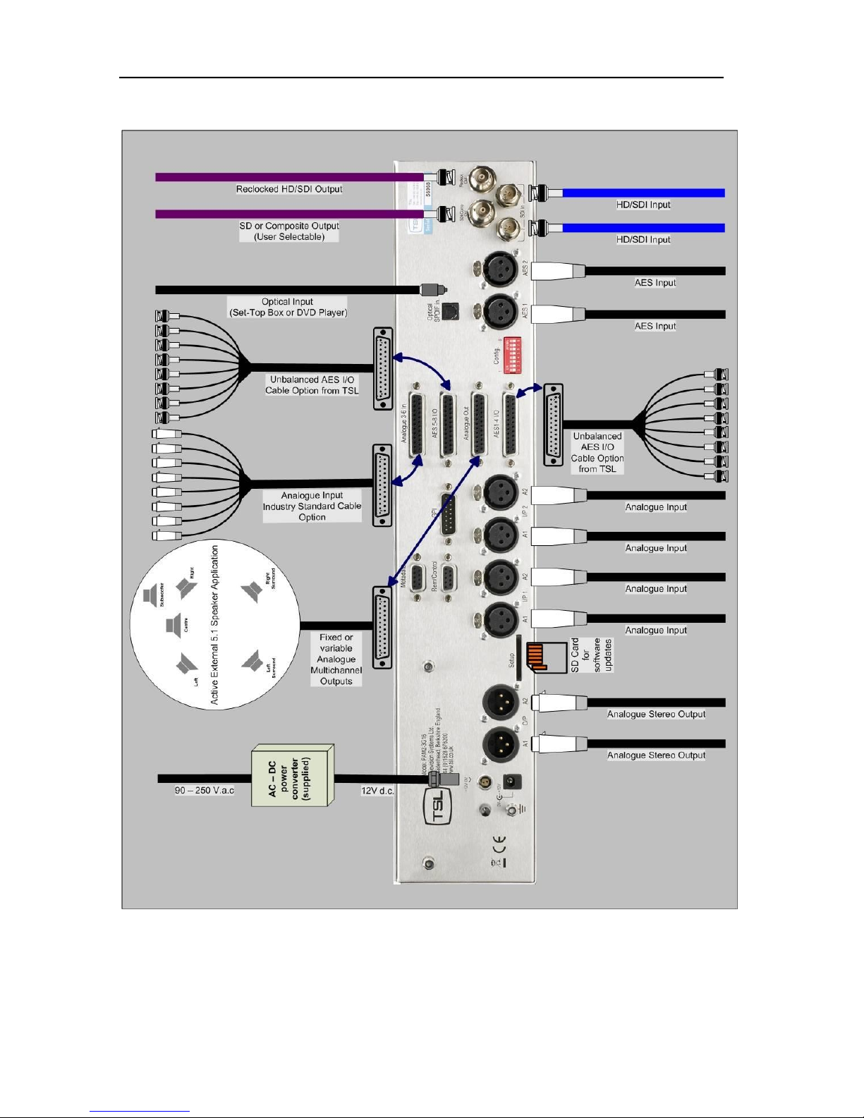
PAM2-3G16 Hookup Schematic
Page 10
P a g e | 10
PAM2-3G16 User Handbook Issue 4
Page 11

P a g e | 11
PAM2-3G16 User Handbook Issue 4
2.0 Operation.
The PAM2-3G16 is designed to be user friendly and intuitive to operate. The menus and functions will
feel familiar to both users of TSL multichannel audio monitoring products and those buying a TSL
solution for the first time.
Important Note: PAM2-3G16 ships with a default 0dBu reference level set to
-18 dBFS, the default operating scale is EBU Digital. A simple power up sequence may be used
to alter the operating reference level to -20 dBFS with a default EBU Digital operating scale.
For -20 dBFS default operation – apply DC power to the rear power connector whilst
simultaneously pressing buttons 6 and 8. The following message will appear on the right hand
OLED signalling a successful operation.
“Default memories cleared Restored Factory - 0dBu = -20dBFS”
For -18 dBFS default operation – apply DC power to the rear power connector whilst
simultaneously pressing buttons 6, 7 and 8. A message will appear on the right hand OLED
signalling a successful operation.
“Default memories cleared Restored Factory - 0dBu = -18dBFS”
To set global reference level and meter parameters outside of the standards described, please
refer to section 2.10.1 of this handbook.
Page 12
P a g e | 12
PAM2-3G16 User Handbook Issue 4
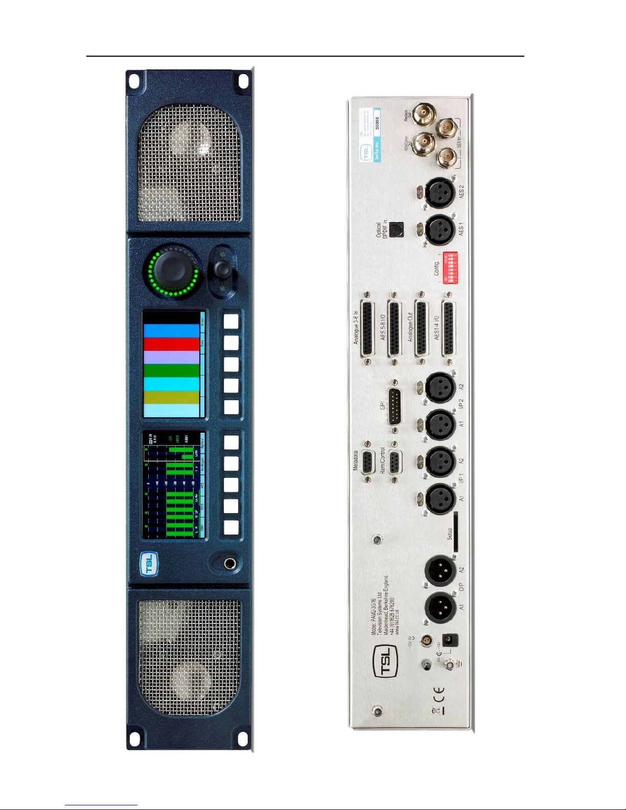
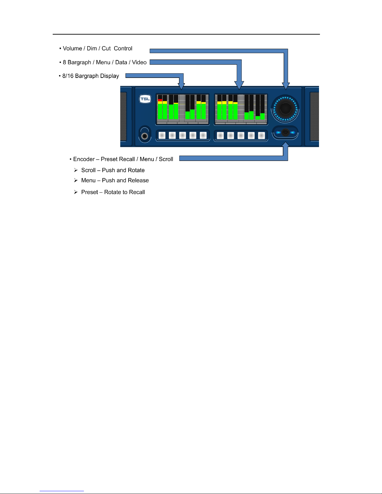
2.1 Controls and Displays
PAM2-3G16’s menus and features are navigated via a multi-function encoder and a bank of ten
pushbuttons. The diagrams below give an overview of the front control panel.
• The left hand OLED screen displays bargraphs 1-8 in Full-screen mode and bargraphs 1-16 when
Menu / Data or Video modes are activated.
• The right hand OLED screen displays bargraphs 9-16 in Full-screen mode and Menu / Data or
Video screens when activated.
• The lower rotary encoder is used to activate the ‘Scroll To Hear’ feature and to access Menus and
Presets.
• The volume knob is used to internal/external loudspeaker and headphone levels. The control also
features a ‘push’ action which Cut/Dim loudspeaker audio.
Page 13
P a g e | 13
PAM2-3G16 User Handbook Issue 4
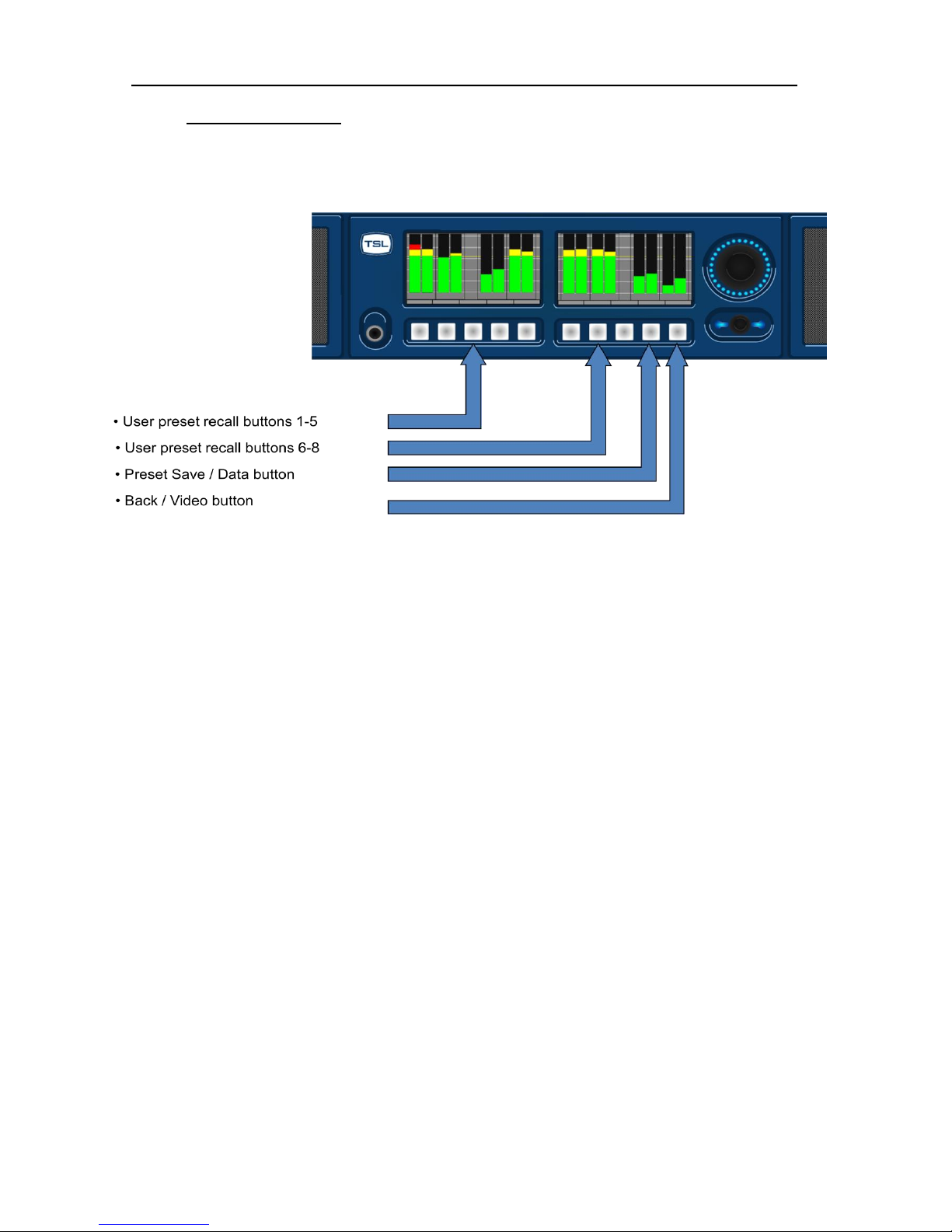
• The 5 buttons located below the left hand OLED screen are used to recall presets 1-5
• The Factory Default condition ships the following User Presets pre-programmed on buttons 1-5
respectively. These may be overwritten by customer programmed presets; defaults can be restored
via the reset procedure described in Section 2.11 of this handbook.
1. SDI 1 Input Pair 1
2. SDI 2 Input Pair 1
3. AES Input Pair 1
4. Analogue Input Pair 1
5. Optical Input (Digital Audio Pair 8)
• The first 3 buttons located below the right hand OLED screen are used to recall presets 6-8 and to
restore system default conditions during a power up sequence.
• The 9th button which located below the right hand OLED screen is used to toggle the Data and
Loudness Histogram Screens when in Full-screen mode and to save User Presets when in
Menu mode.
• The 10th button located below the right hand OLED screen is used to toggle the Video Screen when
in Full-screen mode and to navigate ‘Back’ from Menu modes.
Page 14
P a g e | 14
PAM2-3G16 User Handbook Issue 4
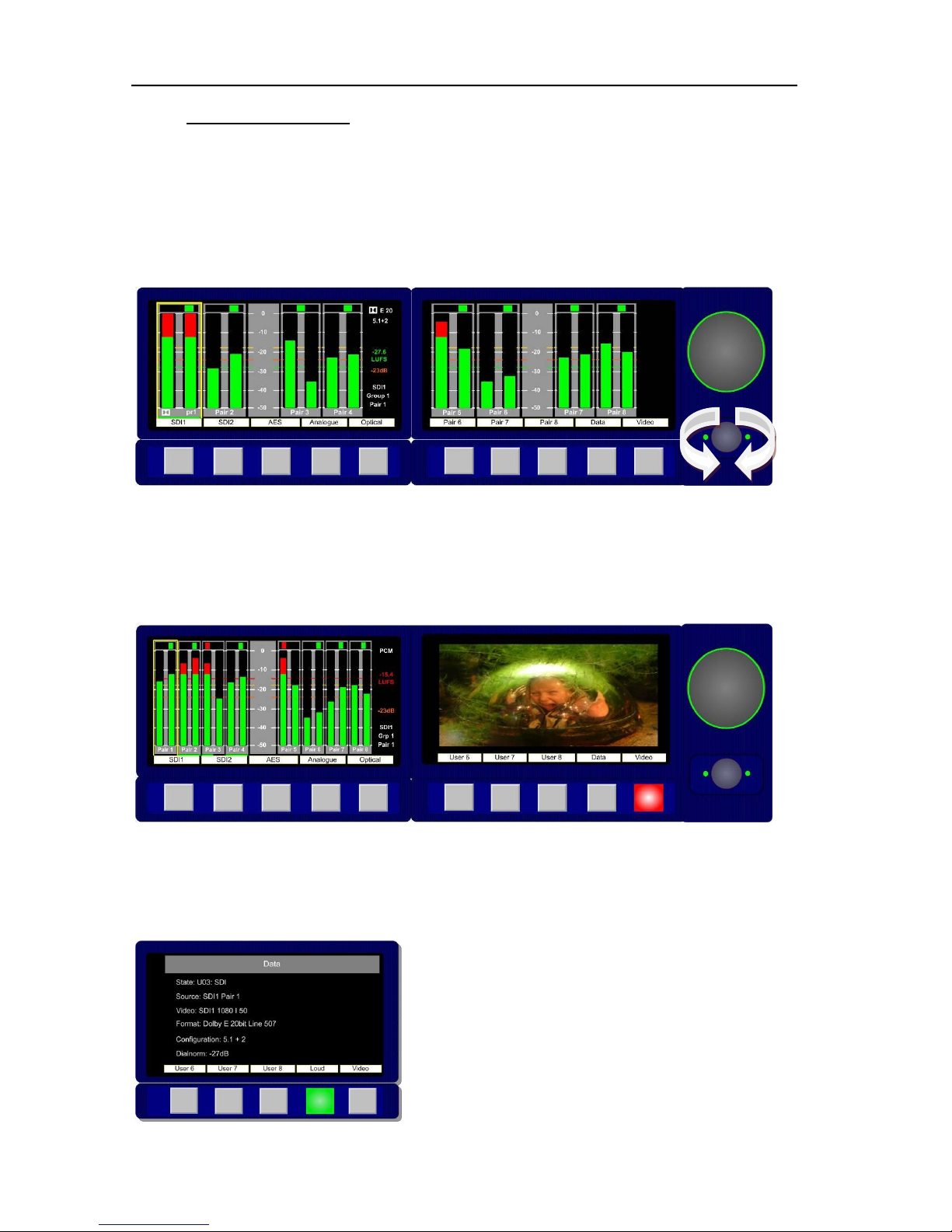
2.2 Top Level Screen Mode
The example below shows PAM2-3G16 in dual screen Metering Mode listening to Group 1 Pair 1 of
an embedded SDI video signal.
2.2.1 Scroll to Hear
Push, hold and rotate the Encoder to move the yellow ‘Scroll To Hear’ box to listen to any of the 16
embedded audio channels. This is the simplest means to navigate PAM2-3G16 and can be used
whenever the unit is not in Menu mode.
2.2.2 Video Confidence Display
Press the Video button to toggle the right hand OLED display and view the input video signal. The
bargraph display is compressed onto the left hand OLED screen.
The aspect ratio of the video display is selected via the Setup Menu.
2.2.3 Data Screen Mode
Press the Data button (button 9) to toggle the right hand OLED display and view the input signal data
screen. The following image shows the Data screen in operation with a Dolby E signal connected via
the Optical connector.
Page 15

P a g e | 15
PAM2-3G16 User Handbook Issue 4
2.2.4 Dolby E Timing and Rate Information
The Data Screen of the PAM2-3G16 displays extended information about any Dolby E and Dolby
Digital sources. This shows the frame rate of the Dolby encoded signal and its timing relative to a
video source where available.
For AES inputs, the frame rate information is displayed as a minimum;
Dolby E 20bit 29.97 - or - Dolby E 16bit 25Hz
For embedded Dolby E sources, the start line position is displayed in the format;
Dolby E 16bit L11
This functionality is also extended to mixed sources. If an AES source is selected for monitoring,
whilst a video source is selected with the same frame rate, then the display will give the approximate
line position of the AES Dolby E start relative to the video. This allows the timing of an AES signal to
be checked either before embedding or after extraction (note the embedder / extractor delays need to
be accounted for in a system). For sources of different frame rates, the display reverts to the Dolby E
frame rate. The video frame rate is already displayed on the top level menu.
Dolby Digital and Digital Plus sources are also identified, although no further information is provided
without a decoder.
All of the above functions are available both with and without on-board Dolby decoding, providing the
source has a correctly formatted SMPTE 337M header
2.2.5 Dim Cut Control
The rotary volume control of PAM2-3G16 also features a push switch cut/dim function. Push the
volume control once to cut the volume to internal speakers, headphones and variable audio outputs.
Pushing the volume control a second time will dim the output level by 12 dB. A final push will return
the output volume to full level – this is indicated by a single LED dot cursor in cut and dim conditions.
2.2.6 LED Brightness Settings
The Setup 2 Menu contains a button to select the operational brightness of the switch and encoder
LEDs. By selecting and rotating the encoder the overall brightness of the LEDs may be changed from
low to high level across 5 graduations. 1 is low, 5 is high.
Page 16
P a g e | 16
PAM2-3G16 User Handbook Issue 4
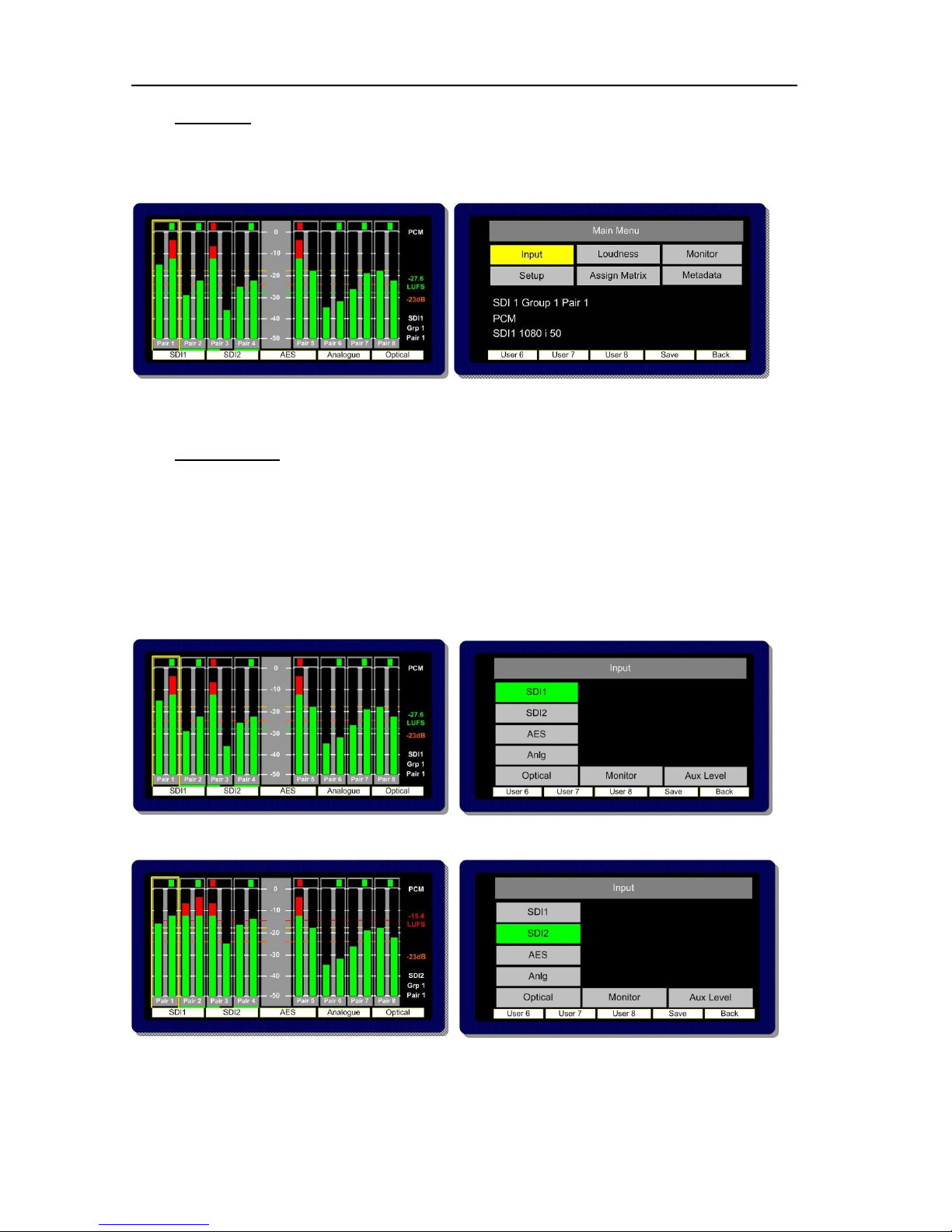
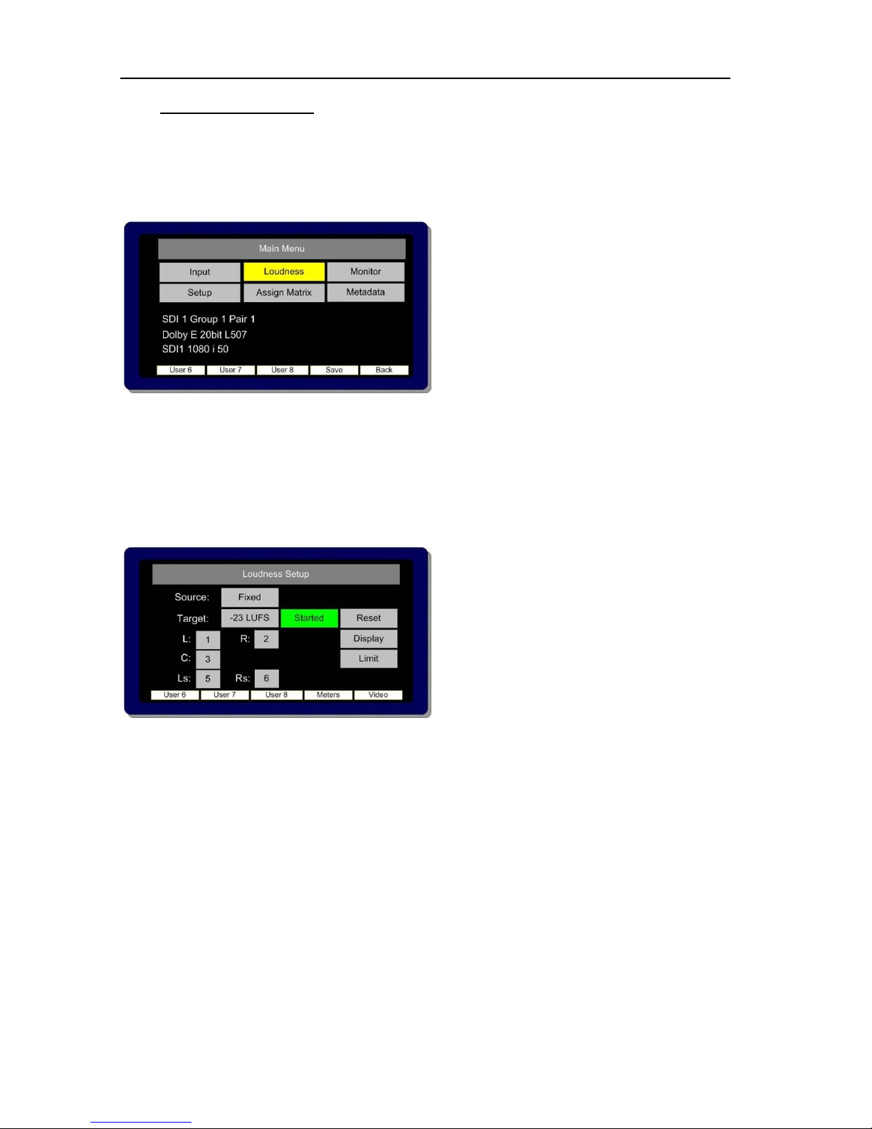
2.3 Main Menu
Press the Encoder to access Main Menu. The encoder is then rotated and pressed to highlight and
select from the displayed Menu options. From any Menu, pressing Back (illuminated red) will exit the
current menu page.
The Main Menu screen also displays information about the current selected input signal as shown in
the photo above.
2.4 Input Selection
PAM2-3G16 ships with User Presets 1-5 programmed to instantly access SDI1, SDI2, AES,
Analogue and Optical TOSLINK inputs. Selecting these presets will directly route either input signal to
the bargraph display. These User Presets may be overwritten however and customised as required.
From the Main Menu screen, Input Menu mode may be selected.
By highlighting and selecting the Input option, SDI, AES and Analogue inputs can be accessed. A
shortcut button enables the user to ‘jump’ to the Monitor Menu once the desired input is selected.
2.4.1 SDI 1 Input
2.4.2 SDI 2 Input
Page 17
P a g e | 17
PAM2-3G16 User Handbook Issue 4
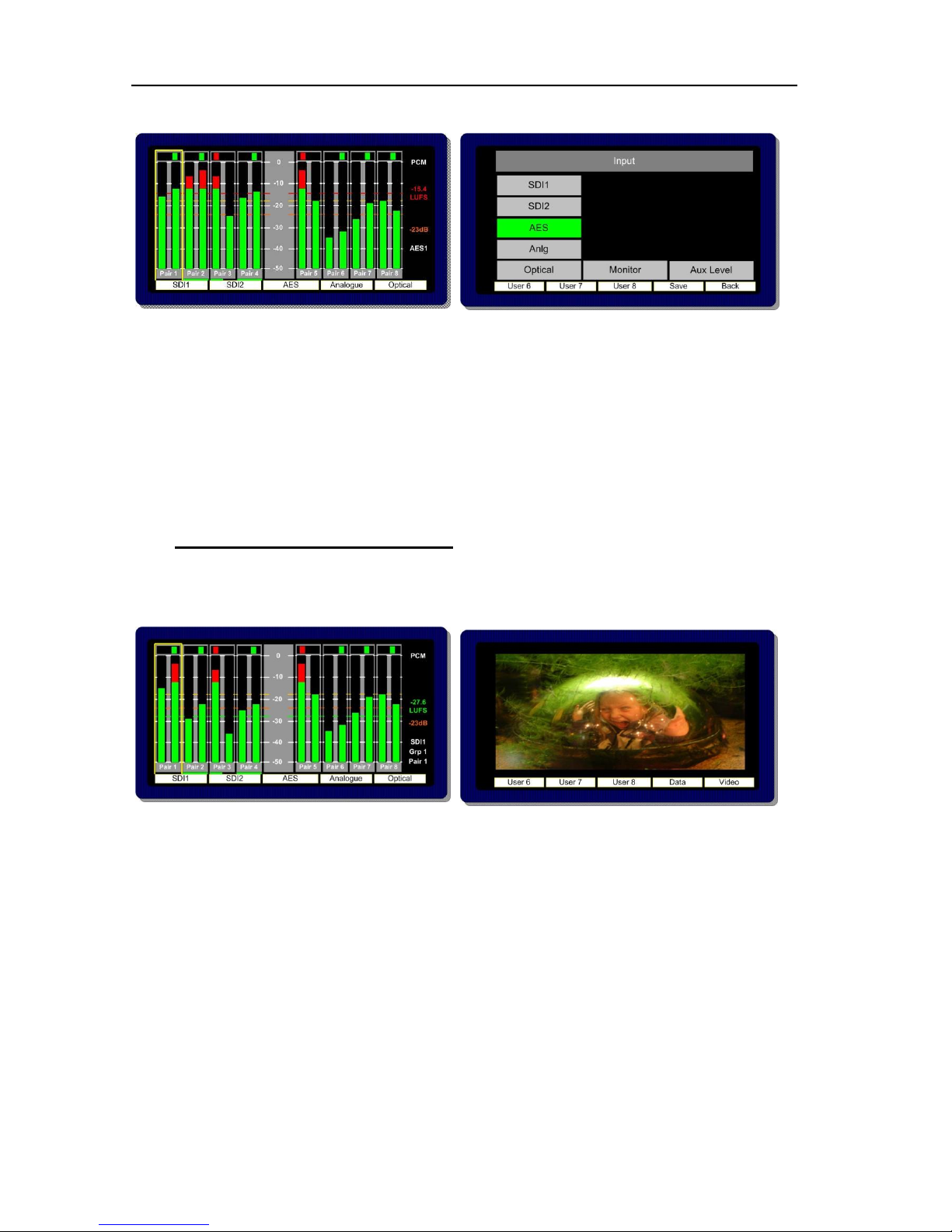
2.4.3 AES Input
2.4.4 Optical Input – PAM2-3G16 is unique amongst rack mount audio monitoring products in that
it features a TOSLINK Optical Input. The Optical Input is selected via Factory Preset 5. When Optical
is selected, AES channel 8 is replaced by the signal received via the Optical connector. This input
may be used to connect directly to a Set Top Box, DVD or CD player and can decode Dolby Digital
or Dolby Digital Plus encoded signals.
2.4.5 Analogue Input
PAM2-3G16 features 6 stereo analogue audio inputs. These may be selected simultaneously by
selecting Analogue from either the monitoring menu or preset buttons. Bargraph pairs 1-6 will display
the respective input audio, pairs 7 and 8 are not used in this mode.
2.5 SDI Input and Video Confidence Display
The Video Display may be activated using button 10 when not in Menu mode. The input video signal
of the SDI Input selected last will be routed to the screen when the audio input selected is either AES
or Analogue.
Page 18
P a g e | 18
PAM2-3G16 User Handbook Issue 4
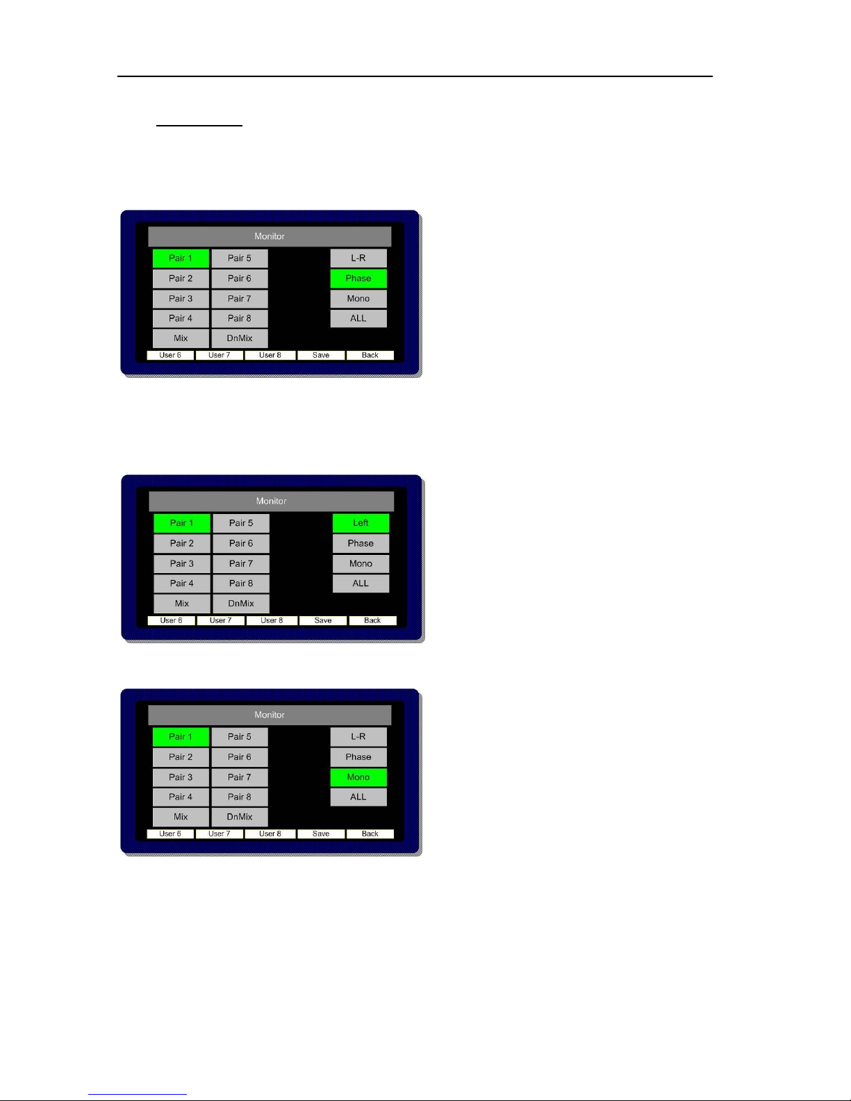
2.6 Monitor Menu
The Monitor Menu is used to activate listening modes not accessible via ‘Scroll To Hear’ selection.
2.6.1 The Monitor Menu features a ‘Phase Swap’ button which enables the user to reverse the
phase of the right signal of a selected audio pair with respect to the right.
2.6.2 Pushing to select L – R enables individual selection of either Left or Right components of the
highlighted stereo pair (or pairs).
The L – R function also enables Left and Right audio components to be swapped.
2.6.3 The Mono mode button mono’s the selected bargraph pair
Page 19
P a g e | 19
PAM2-3G16 User Handbook Issue 4
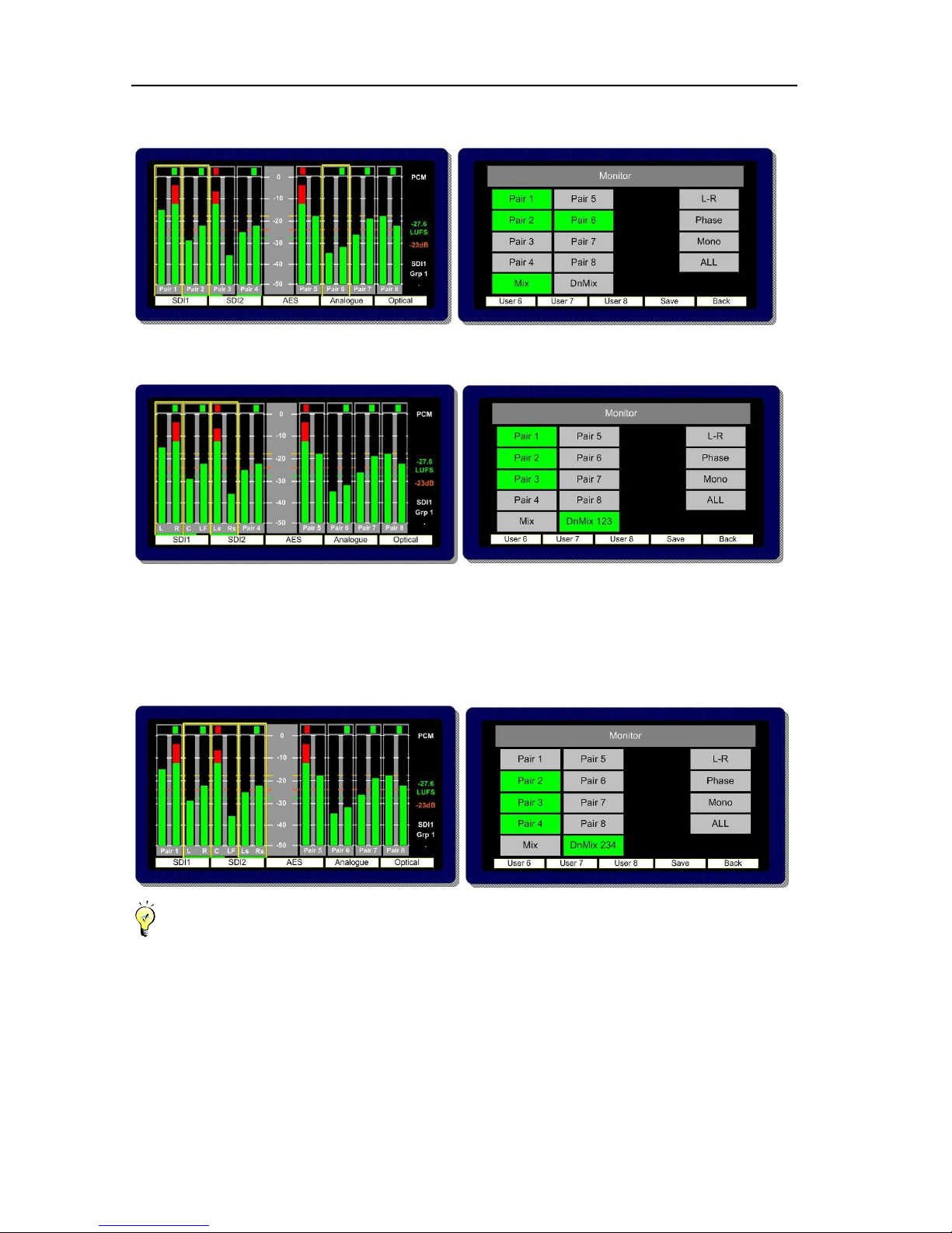
2.6.4 When Mix Mode is activated, multiple bargraph pairs may be selected and monitored as a
mixed stereo pair.
2.6.5 Downmix Mode allows the operator to select an adjacent group of 3 audio pairs (6 audio
channels) and create a stereo Downmix.
By repeatedly selecting the DnMix button, the group of selected audio pairs move from left to right
across the bargraph display enabling the user to Downmix discrete 5.1 or 5.0 audio from any location
within the 16 channels displayed. Pressing and rotating the Downmix button also enables the user to
scroll through the pair’s selection in the sequence 123, 234, 345, 456, 567 and 678, downmixing the
appropriate surround sound audio signals as desired.
The Downmix Mode assumes that audio channels are presented in the correct SMPTE order (L, R,
C, Lfe, Ls, and Rs). The Downmix Mode uses the ITU-R BS.775 algorithm standard.
Once the 5.1 audio components are selected and Downmixed, the selection can be stored as a
User Preset to a Hotkey (see Storing User Presets) and recalled at the press of a button.
Page 20

P a g e | 20
PAM2-3G16 User Handbook Issue 4
2.6.6 Split Mono Input Selection
The Scroll to Hear function of the PAM2-3G16 features a special operational mode which enables
the operator to select to listen to two non adjacent mono audio channels.
By scrolling the yellow Hear Box to the first of the desired mono channels the LEDs on either side of
the rotary encoder will flash for a period of 3 seconds. During that time the user is permitted to turn the
encoder (without pressing) to select a second non adjacent mono audio signal. Once the selection is
made the LEDs will stop flashing and the resultant selection is heard through the loudspeaker or
headphone outputs.
Note; A Split Mono selection is indicated on the front left hand screen in the lower right text window.
The selection may be saved as a User Preset for instant recall (see Saving User Presets).
Note; Split Mono selection uses the Assign Matrix section of the PAM2-3G16 in order to create a
pair of non consequential audio channels. When a Split Mono pair is defined, the Assign Matrix
represents the resultant signal selection as illustrated below.
Page 21

P a g e | 21
PAM2-3G16 User Handbook Issue 4
2.7 Front Switch Monitor Select Mode
In order to further enhance hands on operation of PAM2-3G16, an operational mode exists which
enables the user to toggle between the standard front panel operation of 8 user preset recall switches
below the OLED displays and direct access to up to 6 monitoring mode selector buttons.
By simply holding button 10 (Video Button) for a period of more than one second, the display of
buttons 1-8 switches from the standard operating view of User Preset recall selection to one giving
direct and instantaneous access to a number of Monitoring Menu features.
The display changes depending on the whether the signals currently monitored are Dolby E, D, DD+
or PCM audio. The images below represents the front panel view for Dolby encoded signals and PCM
audio respectively.
Dolby
PCM
Page 22

P a g e | 22
PAM2-3G16 User Handbook Issue 4
DnMix
Downmix Mode allows the operator to select an adjacent group of 3 audio pairs (6 audio channels)
and create a stereo Downmix.
By repeatedly selecting the DnMix button, the group of selected audio pairs move from left to right
across the bargraph display enabling the user to Downmix discrete 5.1 or 5.0 audio from any location
within the 16 channels displayed. Repeatedly pressing Downmix button also enables the user to
scroll through the pair’s selection in the sequence 123, 234, 345, 456, 567 and 678, downmixing the
appropriate surround sound audio signals as desired.
The Downmix Mode assumes that audio channels are presented in the correct SMPTE order (L, R,
C, Lfe, Ls, and Rs). The Downmix Mode uses the ITU-R BS.775 algorithm standard
ALL (Non Dolby)
By selecting ALL, the operator can select the group of 6 audios from 2 groups which corresponds to
the 5.1 audio signal. Once a 5.1 group has been defined, the 5.1 audio stems are routed to the
external speaker outputs in the correct SMPTE order (L, R, C, Lfe, Ls, and Rs).
By repeatedly selecting the ALL button, the group of selected audio pairs move from left to right
across the bargraph display enabling the user to route discrete 5.1 or 5.0 audio from any location
within the 16 channels displayed to the external variable audio connectors in order to feed external
active 5.1 speaker systems. Pressing and rotating the ALL button also enables the user to scroll
through the pair’s selection in the sequence 123, 234, 345, 456, 567 and 678
ALL and DRC (Dolby Only)
The Dolby monitoring menu includes options called ALL and DRC. When used with a 5.1 loudspeaker
monitoring system ALL routes the decoded 5.1 audio to the multichannel outputs. In DRC mode, the
Dolby decoded 5.1 output is affected by Dolby DRC metadata and adjusted accordingly. If the
monitoring mode is switched away from ALL or DRC then the Centre, Lfe, Ls and Rs speaker
channels are muted and only the Left and Right channels are active. The 5.1 monitoring selections
enable a user to ‘solo’ individual surround sound signals to check the integrity of their audio.
The DRC listening mode can be used in conjunction with either ALL or Lt Rt (Lo Ro) modes and
switches Dynamic Range Compression into the monitoring output signal path providing DRC is
activated with the Dolby Metadata component of the encoded signal. DRC monitoring mode can be
selected via the DRC button in the enabling the user to hear the effect of dynamic range compression
on the decoded signal and hence check the integrity of the audio heard by the consumer.
Lt Rt (Dolby Only)
By pressing the LtRt button when PAM2-3G16 is decoding a Dolby E, D or DD+ signal, a stereo
Downmix will be selected. This is the default listening/monitoring condition for a Dolby signal and is
derived using the originally authored Dolby metadata thus enabling the user to hear the effect of
stereo downmixing as heard by the consumer.
Phase
The Monitor Menu features a ‘Phase Swap’ button which enables the user to reverse the phase of
the right signal of a selected audio pair with respect to the right.
Mono
The Mono mode button mono’s the selected bargraph pair.
Page 23
P a g e | 23
PAM2-3G16 User Handbook Issue 4
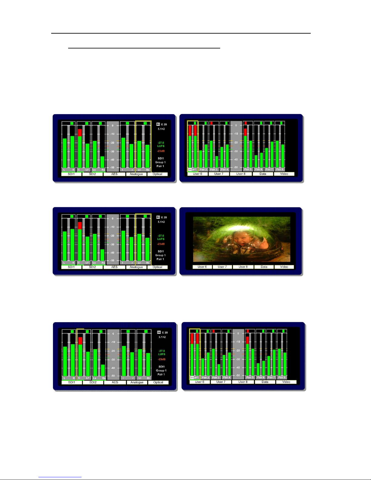
2.8 Dolby E, Dolby Digital and Dolby Digital Plus Monitoring
2.8.1 When a Dolby E, Dolby Digital or Dolby Digital Plus encoded audio pair is selected,
PAM2-3G16 will automatically decode the signal into its component parts and name the stems
according to the Channel Coding information carried within the Metadata. The decoded audio
component bargraph is displayed on the left OLED display – an Lt/Rt (or Lo/Ro) Downmix bargraph
pair is created from the Metadata and shown as a 5th pair on the left screen (shown below).
In Top Level Mode the input bargraph display is shown on the right OLED display with a Dolby logo
now superimposed below the decoded bargraph pair (as shown).
The Video Display may be activated using button 10.
2.8.2 Scroll to Hear Mode may be used when monitoring Dolby E, Dolby Digital or Dolby Digital
Plus encoded signals. By pushing and turning the encoder the ‘Hear Box’ can be moved across the
decoded audio channels in the usual way, selecting to listen to Dolby components as desired. In the
example below, the Centre channel has been ‘soloed’ and would be heard equally from the left and
right stereo output channels.
Page 24
P a g e | 24
PAM2-3G16 User Handbook Issue 4
To exit Dolby Decoding Mode, push and hold the encoder for several seconds and the PAM2-3G16
will revert to the Top Level Mode as shown below. The encoder can be rotated to move the ‘Hear
Box’ and select another signal from the top level screen.
2.9 Monitoring using external loudspeakers
The PAM2-3G16 features an intelligent monitoring matrix designed to optimise the use of both internal
and external loudspeaker systems. Connection of either Stereo or 5.1 loudspeaker systems is
accommodated and monitoring modes automatically configured to ensure that only the audio
components selected are those that are heard using the appropriate output channels.
For example; when listening to a stereo Downmix through a 5.1 surround sound loudspeaker
system, only the left and right speakers are active whilst the centre, LFE and surround speakers are
muted. Dedicated multichannel monitoring modes ALL and DRC route surround audio components to
5.1 loudspeakers in the correct channel order without the need for complex routing configuration.
The table shown in Section 2.9 explains the default monitoring modes based on the various menus
and DIP switch selections detailed in the following descriptions.
De-embedded or decoded multichannel audio (Dolby or discrete PCM) is automatically routed to the
AES and analogue outputs connectors. The rear panel located DIP Switch includes a selection to
mute internal loudspeakers and to set AES and analogue outputs to variable level (adjusted by the
front panel volume control).
Stereo or 5.1 external loudspeakers can be connected (see the application diagram in front of this
Handbook).
2.9.1 Discrete PCM 5.1
The non-Dolby monitoring menu also includes an ALL option. By selecting ALL the operator can
select the group of 6 audios from 2 groups which corresponds to the 5.1 audio signal. Once a 5.1
group has been defined, the 5.1 audio stems are routed to the external speaker outputs in the correct
SMPTE order (L, R, C, Lfe, Ls, and Rs).
By repeatedly selecting the ALL button, the group of selected audio pairs move from left to right
across the bargraph display enabling the user to route discrete 5.1 or 5.0 audio from any location
within the 16 channels displayed to the external variable audio connectors in order to feed external
active 5.1 speaker systems. Pressing and rotating the ALL button also enables the user to scroll
through the pair’s selection in the sequence 123, 234, 345, 456, 567 and 678.
Page 25

P a g e | 25
PAM2-3G16 User Handbook Issue 4
This function ensures that an embedded discrete 5.1 signal can be monitored regardless of the
location of the 5.1 stems. The user can store different settings for monitoring discrete 5.1 audio in their
User Presets.
The ALL listening mode mutes the internal loudspeakers and routes the selected audio to 5.1
external loudspeakers via the variable multichannel analogue and AES connectors. Selection can be
saved as user presets for instant recall.
2.9.2 Dolby E, Dolby Digital and Dolby Digital Plus
The Dolby monitoring menu includes options called ALL and DRC. When used with a 5.1 loudspeaker
monitoring system ALL routes the decoded 5.1 audio to the multichannel outputs. In DRC mode, the
Dolby decoded 5.1 output is affected by Dolby DRC metadata and adjusted accordingly. If the
monitoring mode is switched away from ALL or DRC then the Centre, Lfe, Ls and Rs speaker
channels are muted and only the Left and Right channels are active. The 5.1 monitoring selections
enable a user to ‘solo’ individual surround sound signals to check the integrity of their audio.
The DRC listening mode can be used in conjunction with either ALL or Lt Rt (Lo Ro) modes and
switches Dynamic Range Compression into the monitoring output signal path providing DRC is
activated with the Dolby Metadata component of the encoded signal. Line and RF DRC monitoring
modes can be selected via the DRC button enabling the user to hear the effect of either form of
compression on the decoded signal and hence check the integrity of the audio heard by the
consumer.
Page 26

P a g e | 26
PAM2-3G16 User Handbook Issue 4
2.10 Internal and External Monitoring Modes
The table below indicates the various monitoring modes available to PAM2-3G16 users and the audio
signals presented to internal loudspeakers and external connectors when each mode is selected.
Ext Fixed/Variable D25 refers to both analogue and AES multichannel 1-8 output connectors whose
modes can be altered via the rear panel DIP switches.
AES outputs 9-16 are fixed level at all times and carry a direct feed of inputs 9-16 of the selected
source whenever the AES or Analogue outputs are in fixed mode. When AES outputs are set to
variable mode, this connector carries a fixed level copy of the signal routed to the variable output
connector.
M onito ring
M ode Internal LS
Ext Fixed -
D25 (Int LS
On)
Ext Fixed -
D25 (Int LS
Of f)
Ext ernal
Va riable
Int ernal LS
Ext Fixed -
D25 (Int LS
On)
Ext Fixed -
D25 (Int LS
Of f)
Ext ernal
Va riable
All Muted Full Full - AES
Only
Full M uted Full Full Full
DRC
(Line o r
RF)
Muted Full Full - AES
Only
Full M uted Full Full Full
Lt R t Lt Rt Full Full - AES
Only
Lt Rt (1st pair
only) 2-4
muted
N/A N/A N/A N/A
Lo Ro Lo Ro Full Full - AES
Only
Lo Ro (1st pair
only) 2-4
muted
N/A N/A N/A N/A
DM ix DM ix Full Full - AES
Only
DM ix (1st pair
only) 2-4
muted
DM ix Full
DM ix (1st pair
only) 2-4
muted
DM ix (1st pair
only) 2-4
muted
* Individual Individual Full Full - AES
Only
Indiv. (1st pair
only) 2-4
muted
Individual Full
Indiv. (1st pair
only) 2-4
muted
Indiv. (1st pair
only) 2-4
muted
* Individual refers to single, paired or multiple audio channels selected from the monitoring menu.
Dolby E nco ded A udio
Discre te A udio
Page 27

P a g e | 27
PAM2-3G16 User Handbook Issue 4
2.11 Data and Metadata Menus
2.11.1 Dolby Metadata. Primarily for use with Dolby E, Dolby Digital and Dolby Digital Plus
encoded audio signals; the Metadata Menu accesses a user selectable group of 7 Dolby Metadata
parameters. By highlighting and selecting any of the 7 options, the user can use the encoder to scroll
through a list of all Metadata settings read by the CAT552 card for Dolby E, Dolby Digital and Dolby
Digital Plus audio and create their own Metadata monitoring view.
Dolby E signals might consist of up to 8 separate programmes (ie: 5.1+2 contains 2 programmes,
2+2+2+2 contains 4 programmes etc) and each programme may be configured with different
Metadata parameters.
The example below shows the selection of
Dolby E PGM 1 as the default for the Metadata screen associated with the selected 5.1 audio signal.
The Setup Menu allows the user to select
which programme the Metadata is read from. The screen below shows the E prg# selection on the
Setup window. By selecting E prg# the user may scroll through Dolby E programme numbers 1 to 8
and select the appropriate programme number. This setting may be saved as part of a user preset.
Page 28

P a g e | 28
PAM2-3G16 User Handbook Issue 4
2.11.2 Data Screen.
The Data Screen can be toggled on/off from the 9th button on the front panel when in Top Level
Mode. When the Loudness feature is activated, the Data selection will toggle between
Bargraph/Data/Loudness.
The Data Screen provides up to 6 fields of feedback regarding the signal being monitored and the
operational status of PAM2-3G16.
State: The current User Preset name and number
Source: The selected input signal and channel
Video: The format of the selected video input signal or that of the most recently selected signal should
an audio only source be routed to the bargraph display
Format: Data pertaining to the audio component of the selected signal (ie PCM or Dolby encoded).
The Dolby line position is also displayed where appropriate; however, this is replaced with the Dolby
signal frame rate when the encoding rate is incompatible with that of the host video signal.
Configuration: Channel configuration of a Dolby encoded signal
Dialnorm: Dialnorm value of a Dolby encoded signal
Page 29

P a g e | 29
PAM2-3G16 User Handbook Issue 4
2.12 Setup Menu 1 and 2
Setup Menu 1 includes options for different Scales, Reference Levels, Peak Hold, Dolby E
programme, Dolby E Video compensation delay, Video Window and Audio delay. By highlighting
and selecting a parameter, the user can scroll through the available options and tailor PAM2-3G16 to
suit their needs .
2.12.1 Bargraph Settings and non-system default conditions.
The standard operating conditions of PAM2-3G16 are described during the Introduction to this
Handbook in section 2.0. Non system operating defaults for level and scale options may be set as
follows:
From initial power up, go into the SETUP menu and choose the desired values for Meter type and
alignment levels. These will be echoed on the left display as you choose them.
Having chosen your defaults, move the yellow highlight box to "SETUP2", but do not go into the lower
menu.
Then press and hold the encoder without turning it for 15 seconds (the screens will refresh after 1
second, which is the Dolby scroll exit timer finishing - ignore this)
After 15 seconds, you should get a message saying "Default Setup stored SW10 to proceed".
You should now find all memories, factory or user, have the chosen defaults
The factory memories can only be changed by repeating this process (or by a factory reset), but the
user memories can be configured as desired (so you can have different metering types on different
presets).
NOTE, however, that if you repeat this procedure to change the factory memories, then ALL user
memories will have their metering defaults over-written.
The bargraph example below shows a selected EBU Digital scale with -18dBFs reference level
(yellow indicator line on Bargraph display).
The example below shows the previous EBU Digital bargraph scale changed to display a BBC PPM
bargraph.
Page 30

P a g e | 30
PAM2-3G16 User Handbook Issue 4
The dBFS parameter can be used to alter the 0dB reference level from between -12 and -24 dBFS.
The Zero parameter selects the offset level between the Zero dBFS setting and the onset of Peak
indication (the point where the bargraph changes colour to red).
When set to Block mode, the Peak parameter enables the user to choose to illuminate the indication
between zero dBFS and the peak level in yellow.
The Hold parameter activates a peak hold indication when switched on.
2.12.2 Dolby E Video Delay
The PAM2-3G16 features a 1 frame (40 ms) video delay setting which can be inserted into the
Downconverted video display to compensate for the latency caused by decoding a Dolby E signal. If
selected and activated, the delay will be switched into the video signal path automatically when a
Dolby E input signal is detected and decoded. The Video Confidence window on PAM2-3G16 will be
subject to a 1 frame delay when the video delay mode is active.
Page 31

P a g e | 31
PAM2-3G16 User Handbook Issue 4
2.12.3 Audio Delay
The TSL PAM family of audio monitoring units is unique in that they feature the ability to insert up to
250ms of delay into the audio monitoring signal path (headphone, internal speaker or variable level
outputs). This is designed for use in situations where the unit is being used in conjunction with a video
system which introduces latency (for example; multiviewer and LCD screen combinations) and so the
audio monitoring system must be delayed to compensate.
By selecting ‘Audio dly´ from the Setup Menu whilst pushing and rotating the encoder, audio delay in
1ms steps up to a total value of 250ms may be selected. The selection must be stored as part of the
associated User Preset and is not set as part of the system default. This allows the user to configure
different settings for dissimilar signal types or for inputs and modes where audio delay is not required
(such as analogue audio sources without associated video).
The delay feature auto-compensates for decoding latency introduced by Dolby D and E decoding. For
example, if an audio monitoring delay setting has been configured for 80ms whenever the SDI1 input
is selected and the embedded audio contains a Dolby E channel which is decoded, the audio delay
algorithm will reduce the preset setting by 40ms so that the overall delay remains constant; 40ms
(Dolby E decode latency) + 80ms (SDI 1 delay preset) – 40ms (auto compensation) = 80ms.
2.12.4 Setup Menu 2
Setup Menu 2 is used to access the global system settings and software update processes (for
information on software updating see Section 2.15). Setup 2 is accessed from a button within the first
level Setup Menu
2.12.5 Locking Presets (Usr Save)
Presets can be locked to prevent them from being accidentally overwritten. Select the Usr save
button and push/turn to lock. The Save function will now become disabled and editing of the User
Preset function de-activated.
Page 32

P a g e | 32
PAM2-3G16 User Handbook Issue 4
2.12.6 LED and OLED Brightness (Bright)
The default brightness level of the OLED displays, button and encoder LEDs can be altered on a
scale of 1 to 5 (brightest) to suit operational conditions. Default setting is 3.
2.12.7 GPI
GPI functionality is described elsewhere within this handbook (see Section 2.17)
2.12.8 Internal Speaker Mute (Int LS)
The Internal loudspeakers may be muted via either a rear panel DIP switch or by using the button
located within Setup 2 menu. If the DIP switch is set to ‘off’ then the function of the on screen button
is defeated. The action of the on screen Internal LS mute switch is preset dependant and not a
system default.
Coupled with the ability to mute the External Speaker outputs (see below) the PAM2-3G16 can be
used with both internal and external speaker systems switching between the two. This setup may suit
applications such as MCR or QC Suites where specific programme content occasionally requires the
attention of full range or 5.1 listening or when two or more PAM2-3G16 operators share a common
external speaker system.
2.12.9 External Speaker Mute (Ext LS)
The External loudspeaker (analogue and AES variable level outputs) connections may be muted
by using the button located within Setup 2 menu. The action of the on screen External LS mute
switch is preset dependant and not a system default.
2.12.10 Preset Standard Auto-Switching (Pst Std)
Preset Standard Auto-Switching functionality is described elsewhere within this handbook (see
Section 2.14)
Page 33

P a g e | 33
PAM2-3G16 User Handbook Issue 4
2.12.11 Energy Saver Mode (ScrnSave)
PAM2-3G16 features an energy saving mode which dims the OLED displays after a defined period of
time when activated. The ScrnSave button within Setup2 menu access 4 preset time settings after
which the OLED displays will dim, reactivated once a button is pressed or an encoder turned by one
click. The time out settings available are 5, 10, 20 mins and None.
Page 34

P a g e | 34
PAM2-3G16 User Handbook Issue 4
2.13 Assign Matrix
The Assign Matrix is intended for use in multichannel audio monitoring situations where discrete
surround sound signals are being transported in non SMPTE or unconventional channel order.
The Assign Matrix takes the form of a 16 x 6 router where the inputs can be routed from SDI1, SDI2,
AES or Analogue connections (exclusively). The outputs represent the 6 surround channels of a 5.1
programme and once the matrix is ‘activated’ are displayed as 6 bargraphs on the left OLED.
Standard PAM2-3G16 monitoring modes can be used to derive a Downmix, solo individual channels
or route audio to external surround loudspeakers.
Access to the Assign Matrix is via the Main Menu.
Application Example 1; a clean 4.0 surround mix of Left, Right, Left and Right Surround is
embedded sequentially across channels 3 to 6 of an SDI signal while multiple language mono Centre
channels are embedded elsewhere within the same signal. An operator it needs to be able to
reconstruct each 5.0 surround sound mix for monitoring purposes – the Assign Matrix is designed to
simplify the task and by using User Preset programming to enable instant recall of each monitoring
setup. The images below show how this set up would be achieved using a Centre channel embedded
on channel 16.
The icons within the Assign Matrix screen represent individual channels of a 5.1 programme – by
selecting each individually via the encoder, any mono input audio signal can be routed to that output
channel. Output channels can be muted if they are not required (as Lfe in the example shown).
Page 35

P a g e | 35
PAM2-3G16 User Handbook Issue 4
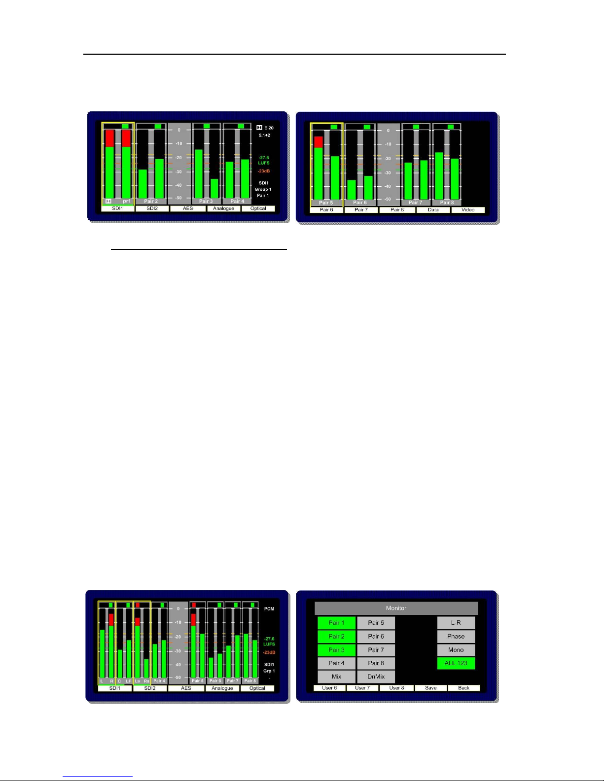
Once the Assign Matrix routing is completed and the matrix activated the following bargraph display
is represented across the left and right OLED screens respectively.
The left hand screen shows a bargraph representation of the output channels with a default condition
of a stereo Downmix whilst the right hand screen provides a reference to the status of the input
channels as defined by the Assign Matrix. The sources of the surround sound components are
denoted by yellow boxes and text identification below the bargraphs. The setup could then be stored
directly to a User Preset button for instant recall.
The Assign Matrix may be used for non-surround applications and is ideal for creating customised
stereo or mono mixes from multiple mono sources (by using Downmix) or for applications such as
‘Solo in Place’ and LCR monitoring.
It is important to note that the Assign Matrix will remain active when associated with a User Preset
state until the Inactive button is pressed.
Page 36
P a g e | 36
PAM2-3G16 User Handbook Issue 4
2.14 Loudness Measurement
ITU-R BS1770 Loudness Setup menu is accessed from the Main Menu.
PAM2-3G16 aims to provide the user with a set of tools which comply with the recommendations of
both the ATSC (A85) and EBU (R128) Loudness committees whilst giving the flexibility to tailor
operation to suit local requirements.
The Loudness Setup menu may be used to define the parameters used to measure Loudness using
the ITU-R BS1770 algorithm, to select and set the specific audio channels under test and to start/stop
measurement manually. The resultant Loudness measurement may be observed via either the
Bargraph Display or from the Loudness Histogram which is accessed via the Data button.
The Loudness implementation does not require the operator to listen to the audio components being
measured as the location of the Hear Box and Loudness Cursor may be independent of one another
(Fixed and Dolby source modes).
2.14.1 Source Selection.
The PAM2-3G16 comprises 4 modes of operation for use when measuring Loudness from a User
determined audio signal. In Fixed mode the user is able select whichever channels are subject to
measurement, Follow mode takes a measurement of a 5.0 signal determined by the location of the
yellow ‘Hear’ box and finally Dolby mode automatically selects the surround sound components of a
decoded Dolby E, Digital or Digital Plus signal.
Off Mode: The Loudness menu Source Selection includes an OFF position for use when the
Loudness measurement is not required. This switch position disables all onscreen representation of
Loudness measurement including the Target value, Measured value, Histogram and Menu
selection
Page 37

P a g e | 37
PAM2-3G16 User Handbook Issue 4
Fixed Mode: Fixed Mode should be used when the audio signal under test should not change despite
the position of the yellow ‘Hear Box’. In the example shown below, channels 1, 2, 3, 5 and 6 are
selected as the L, R, C, Ls and Rs components respectively.
Their selection is denoted by the horizontal green cursor displayed below the ‘pair’ identification.
Providing the user does not switch away from the selected signal input or User Preset, then the
PAM2-3G16 will continue to measure the Loudness of the highlighted audio components. In this mode
of operation PAM2-3G16 does not make the assumption that the audio signals are present in the
correct SMPTE channel order for 5.1 sound – by selecting the channel components individually, non
SMPTE order 5.1 audio can be chosen and measured. Unused channels can also be turned ‘OFF’ for
Stereo, 4.0 or other custom applications. As per the ITU-R guidelines, the LF channel is not subject to
measurement.
Follow Mode: Follow Mode should be used when the audio signal under test is determined by the
position of the yellow Hear Box. In operation, as the user scrolls to hear audio components of the
displayed audio signal, the green Loudness cursor will move accordingly and measure the 5
component signals to the right of the selected source. In this mode of operation PAM2-3G16 makes
the assumption that the audio signals are present in the correct SMPTE channel order for 5.1 sound.
As per the ITU-R guidelines, the LF channel is not subject to measurement.
Dolby Mode: When decoding a Dolby signal, the Loudness measurement feature can be set to
automatically select the appropriate audio components of the 5.1 programme. Since the PAM2-3G16
identifies the channel configuration via the embedded Dolby Metadata, the Loudness feature uses
this information to define the signal under test.
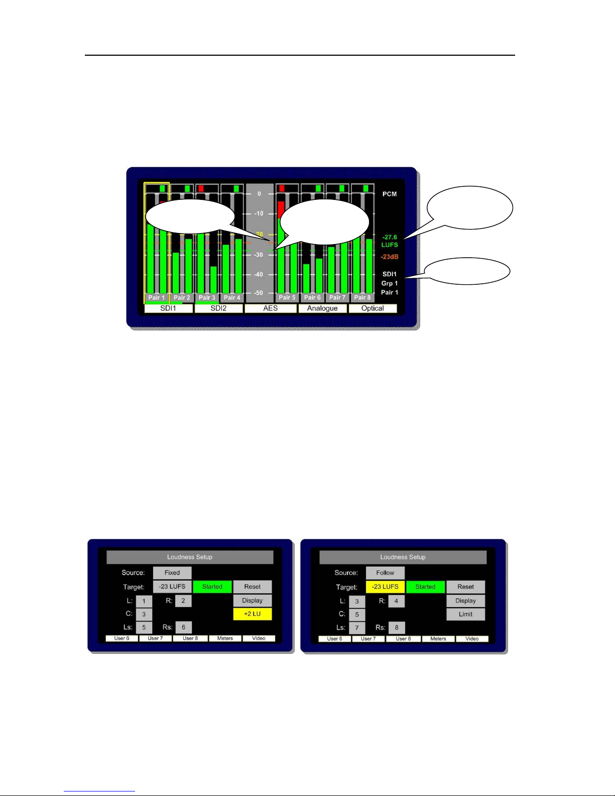
2.14.2 Target Level, Limit Threshold and Red Line Alarm
Page 38
P a g e | 38
PAM2-3G16 User Handbook Issue 4
The purpose of Loudness measurement is to ensure that TV programme audio content is produced,
distributed and ultimately transmitted at a level which does not inconvenience the listener and/or
contravene any local or national regulations. PAM2-3G16 helps the broadcaster to monitor the
Loudness of programme audio content by comparing the measured level against a user defined
Target Level (this might be figure determined by a regulator). A threshold Limit above or below the
Target value determines the point at which the Loudness value displayed changes from green to red.
The onscreen information is described below.
The Target Level can be set within a range of +13 to -30 or it can be defined by the Dialnorm of a
decode Dolby signal. The value is displayed as an orange numerical value to the right of the left
OLED screen. An orange reference cursor is also displayed across the bargraphs.
The derived Loudness figure is indicated as a dynamic red or green numerical value using either
LKFS or LUFS units of measurement. A moving cursor follows the LFS value as it changes
dynamically with both number and cursor changing colour from green to red as the Target Value plus
Limit (if set) is exceeded.
The Limit Value at which a Loudness value ‘red lines’ can be set at up to +6 LU above the Target
Value. At the point at which the ‘Red Line’ limit is reached, PAM2-3G16 triggers an output GPI via
the D15 rear connector. This can be used for external Alarm notification and/or to control a third party
Loudness control device.
Target Value
Measured
Dynamic
Value
Measured
Value – Moving
Cursor
Target Value –
Reference Line
Page 39

P a g e | 39
PAM2-3G16 User Handbook Issue 4
2.14.3 Start, Stop and Reset Triggers
In order that Loudness measurement is targeted towards specific programme content, PAM2-3G16 is
equipped with the ability to Start and Stop (pause) measurement cycles. These functions can either
be triggered manually from the on screen button or from a GPI via the D15 connector at the rear of the
unit.
The action of restarting measurement after a ‘stop’ is executed recommences calculation of
Loudness from the previous value or values. This methodology ensures that programme loudness
measurement can be achieved outside of scheduled interruptions such as commercial breaks or
announcements. A means to integrate this could be to use studio or playout automation to
start/stop measurement via the GPI.
The Reset button discards any previously measured values enabling a new calculation to begin once
the Start button is activated once more.
2.14.4 Histogram Display and Integration Settings
The Display button within the Loudness Setup menu provides access to three integration modes by
which the resultant loudness level can be displayed as either a numerical value, moving line or via the
Histogram.
The sample for all Loudness measurement is set internally at 400ms. The 3 modes of display are as
follows;
• A 3 Second sliding window.
• Integrated Measurement over the entire duration of any clip/programme. Control achieved via the
Start/Stop/Reset buttons (soft or GPI)
• Gated: Similar to Integrated except that any sample lower than the a -8dB gating level is discarded.
At the time of writing (September 2010) the use of gating for ITU-R BS1770 loudness measurement
was being discussed and 8dB suggested as a suitable threshold value pending agreement.
Page 40

P a g e | 40
PAM2-3G16 User Handbook Issue 4
The Loudness Histogram is recalled via the 9th button at the Top (Bargraph) Level by toggling the
DATA button between Data/Loud/Meter modes. The Histogram view can display loudness against
time over a 2, 10, 20, 40 and 80 minute period. The scale shows variation of +/- 6 LU either side of
the user defined Target Level. There are direct access buttons at the top of the display which can be
used to toggle between the two time period displays, three Integration modes and the Loudness
Setup menu (via the Loudness History button).
Any measured values which exceed the Target level are shown in red. Over Target values which
then exceed Limit are then clipped and do not extend to show peak. This gives the user a
comprehensive and instantaneous reference to the behaviour of audio within the tested programme
material.
The diagram below shows a programme Histogram displaying a Target level measurement with a
Limit level set at +4 LU which is being exceeded at three points
Page 41

P a g e | 41
PAM2-3G16 User Handbook Issue 4
2.15 Preset Standard Rules
The Preset Standard Rules feature within the Setup 2 menu enables PAM2-3G16 to automatically
switch between User Presets depending on the input signal format. Each SDI monitoring mode or
User Preset is subject to the action defined by the Preset Standard (Pst Std) button however the
default operating condition renders the setting irrelevant unless the button is pushed and a change
activated.
The Preset Standard (Pst Std) button has 3 user states.
• ALL is the default condition and is used in normal operation. By definition, when Preset
Standard is set to ALL, the PAM2-3G16 operates as usual and is oblivious to changes to
input signal types, auto sensing and functions as normal.
• HD Only should be selected as part of a User Preset which is intended to be automatically
activated whenever an HD signal is received.
• SD Only should be selected as part of a User Preset which is intended to be automatically
activated whenever an SD signal is received.
In use, when monitoring modes are being setup and saved as a User Preset which will be subject to
Preset Standard rules, the Pst Std selection must be made and saved as part of the preset or
presets.
Important: For Preset Standard to work, the SD preset should be stored to the left and directly
adjacent to the HD preset on a pair of front panel User Preset buttons. The SD button must first be
pressed to recall said mode in order to activate automatic switching operation.
Application Example; SDI 1 input is cabled across a TV Station transmission which switches
between SD and HD material. The SD signal always contains an embedded stereo audio programme
on Group 1 Pair 1; the HD signal comprises a Dolby E signal on pair 2 with an encoded 5.1
programme. The operator wants to hear the stereo programme when an SD signal is present and the
Lt Rt Downmix decoded from the Dolby E signal when HD is present without having to remember to
switch between listening modes manually. Preset Standard Rules can be used to configure two
independent User Presets between which the PAM2-3G16 will automatically switch as the input
signal standard changes.
The images below show how the application example would appear in operation with the Data button
active and SD Only and HD Only Preset Standard Rules applied to User Preset buttons 6 and 7.
Page 42

P a g e | 42
PAM2-3G16 User Handbook Issue 4
Page 43

P a g e | 43
PAM2-3G16 User Handbook Issue 4
2.16 Auxiliary Input Mixer
The Auxiliary Input Mixer (AIM) is intended for use in environments where users of PAM2-3G16
wear headphones during normal operation and need to listen to an additional audio input signal such
as Intercom (Talkback) mixed into their monitoring feed.
The Auxiliary Input Mixer provides the ability to select exclusively from either an Analogue or AES
audio input and to mix that audio signal into the PAM2-3G16 monitoring output buss. The resultant
signal can be heard through either headphone or the loudspeaker outputs. The selected auxiliary
input signal can be defined as either mono or stereo in order that an associated input signal (such as
a line level mono output from an Intercom Panel or Matrix) can be plugged into the left or right leg of
the selected input and heard through the left, right or stereo outputs of the PAM2-3G16.
Auxiliary Input Mixer can be accessed via the Setup 2 menu where 3 buttons allow the user to
select the desired input, define whether it is mono or stereo and adjust an input level trim. In order that
the input level can be quickly adjusted, the level trim control is duplicated on the Input menu screen.
Auxiliary Input Mixer is a global feature whose parameters and settings are not saved as part of a
User Preset.
Access to the Auxiliary Input Mixer is via the Setup 2 menu.
Aux Source; By using the encoder to select the
Aux Source button, the user can scroll through
the inputs and select the required source to
route to the Auxiliary Input Mixer. Analogue
Stereo Inputs 1 to 6 and AES pairs 1 to 8 are
available for exclusive selection.
Page 44

P a g e | 44
PAM2-3G16 User Handbook Issue 4
Aux M/S; By using the encoder to select the Aux M/S button, the user can define whether the
selected input is to be mixed within AIM as a mono or stereo signal. For example; a mono line level
input from a local Intercom panel might be connected to the left channel XLR connector of analogue
input 1. In order that the operator can hear Intercom audio through both left and right headphone
earpieces he would select the input to be mono so that the left and silent right inputs are summed
together with equal signal sent to both left and right outputs.
Aux Level; The Aux Level control enables the user to trim the level of the selected Aux Input between
‘Off’ and +12dB of gain with respect to the signal monitored by the main PAM2-3G16 monitoring
function. The level adjustment is graduated in incremental steps as the user pushes and rotates the
encoder control.
Note; As the encoder is pushed and turned, the change in trim level cannot be heard until the control
is released.
Aux Level control is duplicated within the Input menu screen in order to provide the user with rapid
access to the trim control.
Page 45

P a g e | 45
PAM2-3G16 User Handbook Issue 4
2.17 System Upgrade, Default Restore and CAT552 Reset
PAM2-3G16 is designed to be field upgradeable. The user will need an SD memory card, a PC and a
card reader.
Format the memory card to FAT16 (or FAT as described in Windows XP). PAM2-3G16 operating
software and occasional Dolby CAT552 updates will be sent to you by TSL in the form of a ZIP file or
may be downloaded from the Product Support area at www.tsl.co.uk. These files must be extracted
directly to the memory card in order to construct the correct file structure for upload.
Once the upgrade file is saved, select the S/Ware function from the PAM2-3G16 Setup menu 2 and
view the current FP (front panel) and FPGA software versions.
Press button 10 to exit the S/Ware mode and insert the SD card.
Then re-enter S/Ware mode, a new menu option should have appeared at the bottom of the screen.
Highlight and select Perform Update.
During an update, the left hand OLED screen displays the progress of each stage of the installation
on a bargraph with a scale 0 to 100%. Front Panel (FP4), FPGA, PIC and Cat552 boards may all be
updated via the SD card procedure. Depending on the file size of the update, the procedure may take
up to 5 minutes to complete and may appear to have stopped – this is perfectly normal.
WARNING: Under no circumstances should power be interrupted during a software update. In
the unfortunate event that this has occurred, PAM2-3G16 may have to be returned to TSL
headquarters in the UK to have its operating system re-installed.
Once the update is complete, power PAM2-3G16 off and then re apply power after 30 seconds
to complete the procedure.
Note: Buttons 6, 7 and 8 should be pressed (6 and 8 to set -20 dBFS as operational default
reference level) during a post update power cycle in order to clear the system memories and
buffers. Please note that this will restore system default conditions and clear any customer
programmed User Presets.
Page 46

P a g e | 46
PAM2-3G16 User Handbook Issue 4
The optional Dolby CAT552 module can be updated using a similar procedure that described for the
PAM2-3G16 operating system. From Setup 2 select Cat 552 to review and update the Dolby card
operating software. Features such as Dolby Digital Plus decoding may be added to the CAT552
module via the update procedure.
The Dolby CAT552 card may need to be reset in the event that it ‘locks’. Select the CAT552 option
from the Setup 2 menu and then reset the card.
2.18 GPI Application
The rear panel GPI connector functionality can be used to Dim/Cut loudspeakers, to recall User
Presets and to control Loudness measurement features. The Setup 2 menu page includes a button
to access the GPI mode selector. The operator can choose to set the GPI connector to operate in
either ‘Latch’ or ‘Momentary’ modes as described in the following section.
Page 47

P a g e | 47
PAM2-3G16 User Handbook Issue 4
2.19 GPI Connectivity
The GPI operation is described pictorially by the pin out diagram shown below.
In Momentary Mode, Dim and Cut GPI's latch in a toggle manner, i.e. one closure to ground toggles
the function ON; the next ground toggles it OFF. In an ON state; the GPI pin is driven low to allow an
LED to be fed from the port. This LED drive is briefly pulsed high at about 100Hz to allow the port to
be read whilst it is driving.
The preset recall GPI’s in ‘Latching’ mode are mutually exclusive.
! Note that the +5V power from this connector is intended to drive a "1-of-N" LED. If multiple LED’s
are to be used simultaneously, then a small external supply will be needed. An internal resistor within
the PAM2-3G16 prevents the +5V rail from being shorted but limits the current available.
Page 48

P a g e | 48
PAM2-3G16 User Handbook Issue 4
2.20 Preset Memories
PAM2-3G16 features 5 Factory and 24 User Programmable Presets, for save and instant recall of
default and favourite settings.
2.20.1 Factory Presets
Rotating the Encoder counter-clockwise activates the Factory Preset window in the right hand OLED
screen. Highlight and select a preset, PAM2-3G16 will revert to Full Screen mode displaying the
selected audio from the preset list shown below.
Last User State returns the PAM2-3G16 to the operational mode last used when the operator
entered the User or Factory Preset condition.
1. SDI 1
2. SDI 2
3. AES
4. Analogue
5. Optical
Last user State
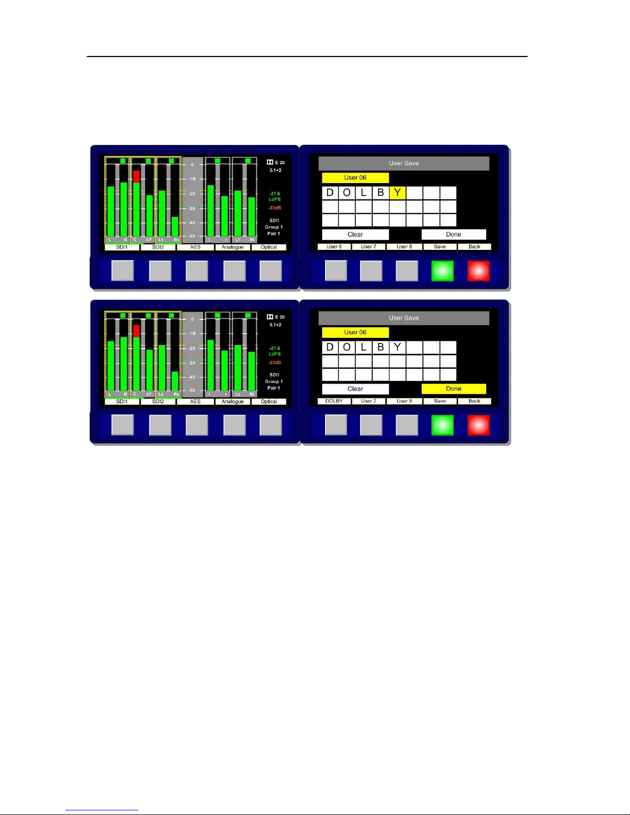
2.20.2 User Presets
In any Main Menu mode, Button 9 is illuminated Green and can be used to save the current
monitoring condition to one of 24 User Presets. By pressing Button 9 the User Preset list is
displayed in the right hand OLED screen. The image below show how a User Preset location may be
selected from a Main Menu screen.
Once the Green save button (button 9) is pressed the User Save menu is activated. Select and
highlight a User Preset location from the list U1 to U24.
Note: U1 to U8 are automatically stored on Preset Recall buttons 1-8.
Page 49
P a g e | 49
PAM2-3G16 User Handbook Issue 4
The text boxes in the User Save menu can be used to name a User Preset. Up to 18 letters or
numbers are available. The example below shows a memory being named as Dolby. Selecting and
pressing Done saves the memory to the chosen location.
Note; the text displayed above the Preset Recall button will display either the first word or 10
characters of text, whichever is shortest.
To recall a User Preset which isn’t stored on Preset Recall buttons 1-8, rotate the Encoder
clockwise to activate the User Preset window in the right hand OLED screen. Highlight and select to
recall a User Preset from locations U01 to U24.
Page 50

P a g e | 50
PAM2-3G16 User Handbook Issue 4
3.0 Connectivity and pin-out details
PAM2-3G16 uses industry standard connectivity wherever possible. The D25 connectivity used for
analogue and AES I/O adopts a pinning convention commonly used for Yamaha Commercial Audio
equipment and breakout cables are readily available at low cost from companies such as
www.cpc.farnell.com www.hosatech.com and many others.
For unbalanced AES I/O connectivity an optional BNC breakout cable, CAB-D25-BNC, is available
from TSL or your local reseller. When used in conjunction with PAM2-3G16, DIP switch 2 (AES
Impedance) must be switched to the 75 ohm position. For more information please refer to section 3.5
of this handbook.
3.1 Analogue XLR Connectors
CONN
PIN
FUNCTION
ANALOG 1
1
GND
ANALOG 1
2
1 IN+
ANALOG 1
3
1 IN-
ANALOG 2
1
GND
ANALOG 2
2
2 IN+
ANALOG 2
3
2 IN-
3.2 AES XLR Connectors
CONN
PIN
FUNCTION
AES1
1
GND
AES 1
2
1 IN+
AES 1
3
1 IN-
AES 2
1
GND
AES 2
2
2 IN+
AES 2
3
2 IN-
Page 51
P a g e | 51
PAM2-3G16 User Handbook Issue 4
3.3 Analogue Output Connector – D25 Socket Pinout on unit, Plug (shown) on mating
cable.
D 25 SOCKET
ON AMU
AUDIO OUT
PIN NO
FUNCTION
1
A8+ (7.1)
14
A8- (7.1)
2
Ground
15
A7+ (7.1)
3
A7- (7.1)
16
Ground
4
A6+ (RS)
17
A6- (RS)
5
Ground
18
A5+ (LS)
6
A5- (LS)
19
Ground
7
A4+ (LFE)
20
A4- (LFE)
8
Ground
21
A3+ (Centre)
9
A3- (Centre)
22
Ground
10
A2+ (FR)
23
A2- (FR)
11
Ground
24
A1+ (FL)
12
A1- (FL)
25
Ground
13
N/C
Page 52

P a g e | 52
PAM2-3G16 User Handbook Issue 4
3.4 Analogue Input Connector – D25 Socket Pinout on unit, Plug on mating cable.
D 25 SOCKET
ON AMU
AUDIO IN
PIN NO
FUNCTION
1
A6R+
14
A6R+
2
Ground
15
A6L-
3
A6L-
16
Ground
4
A5R+
17
A5R-
5
Ground
18
A5L+
6
A5L-
19
Ground
7
A4R+
20
A4R-
8
Ground
21
A4L+
9
A4L-
22
Ground
10
A3R+
23
A3R-
11
Ground
24
A3L+
12
A3L-
25
Ground
13
N/C
Page 53
P a g e | 53
PAM2-3G16 User Handbook Issue 4
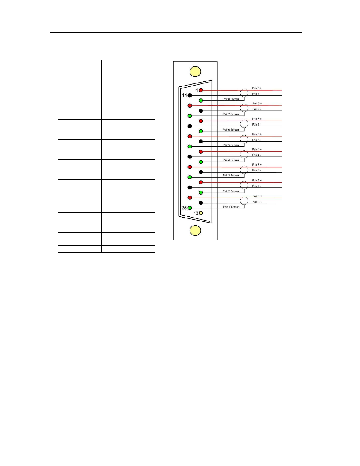
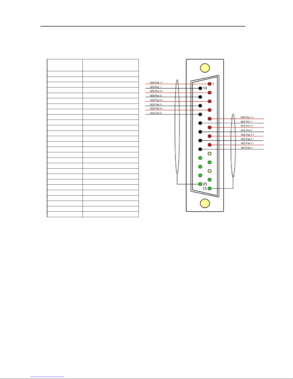
3.5 AES Input/Output Connectors 1-4 and 5-8 – D25 Socket Pinout, Plug (shown) on mating
cable.
D 25 SOCKET
ON AMU
AES INPUTS/OUTPUTS
PIN NO
FUNCTION
1
Ch1&2 / 9&10 In 1+
14
Ch1&2 / 9&10 In 1-
2
Ch3&4 / 11&12 In 2+
15
Ch3&4 / 11&12 In 2-
3
Ch5&6 / 13&14 In 3+
16
Ch5&6 / 13&14 In 3-
4
Ch7&8 / 15&16 In 4+
17
Ch7&8 / 15&16 In 4-
5
Ch1&2 / 9&10 Out 1+
18
Ch1&2 / 9&10 Out 1-
6
Ch3&4 / 11&12 Out 2+
19
Ch3&4 / 11&12 Out 2-
7
Ch5&6 / 13&14 Out 3+
20
Ch5&6 / 13&14 Out 3-
8
Ch7&8 / 15&16 Out 4+
21
Ch7&8 / 15&16 Out 4-
9
N/C
22
Ground
10
Ground
23
Ground
11
N/C
24
Ground
12
Ground
25
Ground
13
Ground
AES connectors may be wired using unbalanced terminations for SPDIF and 75R coaxial
systems.
Optional AES breakout cable CAB-D25-BNC-2 is available from TSL Sales (+44 1628 676200)
and provides BNC Socket to D25 connectivity.
Please note that when using PAM2-3G16 with unbalanced AES audio connections that the
75/110 ohm DIP Switch must be selected prior to use.
When using the D25 for unbalanced AES, AES XLR connectors 1 and 2 may not be used for
balanced AES connectivity.
Page 54

P a g e | 54
PAM2-3G16 User Handbook Issue 4
3.6 GPI Connector – D15 Plug Pinout, Socket on mating cable.
D 15 PLUG
ON AMU
GPI
PIN NO
FUNCTION
1
0V
9
+5V
2
GPI 13 – Loud Alarm
10
GPI 12 – Loud Reset
3
GPI 11 – Loud Start/Stop
11
GPI 10 – Preset 8
4
GPI 9 – Preset 7
12
GPI 8 – Preset 6
5
GPI 7 – Preset 5
13
GPI 6 – Preset 4
6
GPI 5 – Preset 3
14
GPI 4 – Preset 2
7
GPI 3 – Preset 1
15
GPI 2 – CUT
8
GPI 1 – DIM
3.7 Remote Control Connector/ RS 422 - D9 Socket
This is wired for RS422 slave operation.
D9
CONTROL
1
0V 6 0V 2 TX- 7 TX+
3
RX+ 8 RX- 4 0V 9 0V 5 N/C
Page 55

P a g e | 55
PAM2-3G16 User Handbook Issue 4
3.8 Metadata - D9 Socket
This is wired for RS422 master operation.
D9
CONTROL
1
0V 6 0V 2 RX-
7
RX+
3
TX+ 8 TX- 4 0V 9 0V 5 N/C
3.9 DIP switch configuration functions
SWITCH
FUNCTION
1
Video aspect ratio (16:9 Up/4:3 Dn)
2
AES Impedance (75R Up/110R Dn)
3
Internal speaker mute - Up
4
Analogue variable – Up
5
AES variable - Up
6
XLR fixed Out (when set)
7
Not Used
8
Composite Up/SDI Dn
Page 56
P a g e | 56
PAM2-3G16 User Handbook Issue 4
4.0 Notes
There are no user adjustable assemblies/components within this unit.
This unit requires rear support when rack mounted.
In order to affect status changes of the unit using the rear DIP switch, the unit will require re powering
before the changes take effect.
Output analogue levels are adjustable over the following range:
0dBm = 0.775V into 600 i.e. 1mW power dissipation.
0dBu = 0.775V RMS = PPM 4.
Shipping condition, -18 dB ref 0FS = 0dBu output.
Typical European line up: -18 dBu
Typical American line: -20 dBu
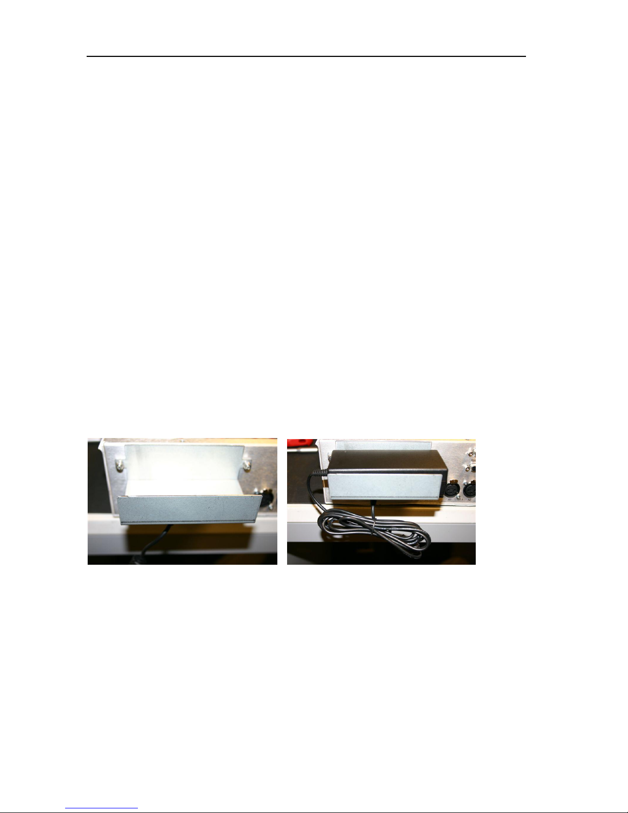
5.0 Power Supply Mounting Bracket
PAM2-3G16 is powered via a supplied external 12 volt, DC supply. For your convenience a rear panel
mounting bracket is also included with the product in order that the power supply can be held in place.
Threaded studs are built onto the back panel of PAM2-3G16 so that the bracket can be attached
simply using a pair of ‘nyloc’ nuts.
Please see the photograph sequence below for details of how to mount the bracket and fit the power
supply.
Page 57

P a g e | 57
PAM2-3G16 User Handbook Issue 4
6.0 General Notes
Please note that some American equipment has the function of the XLR pins 2 & 3 reversed.
TSL product is wired to the European standard
The screw locks on the D25 connectors use UNC 4-40 standard threads.
7.0 PAM2 - 3G8 Technical Specifications
Power Supply
Supply Voltage 12V DC
Power Consumption bc.
Physical Dimensions
Height 88mm (2RU)
Width 483mm (19”)
Depth 320mm
Weight 5100g
Analogue Inputs 1 – 2 ( Input 3-6 refer to section 3.4)
Connector Type XLR Female 3 pin. Pin 1 Gnd, Pin 2 hot, Pin 3 cold.
Signal Balanced line level audio.
Frequency Response 30Hz to 25kHz
Impedance >20k
Inputs AES 1&2
Connector Type XLR Female 3 pin. Pin 1 Gnd, Pin 2 hot, Pin 3 cold.
Standard AES3 (1994) at 48kHz, 44.1kHz or 32kHz
Impedance 110 ohm (balanced.)
Inputs AES 1 to 8 AES I/O, 25 way D type (See elsewhere for details)
Input, HD/SDV 1 &2
Connector Type BNC.
Standard 4:2:2 component with embedded 48Khz audio.
(SMPTE 259M, 292M and 424M)
Impedance 75ohm
Line Output.
Connector XLR 3 pin Male
Impedance 50
Output Levels Through level control with 0dB gain.
Fixed Line O/P Available on D25 (If selected on front panel)
Headphone Output.
Connector Stereo Jack socket type A
Impedance 50
Output Levels Through level control with 0dB gain.
De embedded output
Connector 25 way D type
Impedance 110 Ohm
Output Groups 1, 2, 3 and 4
Page 58

P a g e | 58
PAM2-3G16 User Handbook Issue 4
Video Output
Connector BNC
Impedance 75 Ohm
Output Composite video or SDI (selectable)
Re-clocked Output
Connector BNC
Impedance 75 Ohm
Output Re-clocked serial output of the SELECTED input HD/SDV
AES Output
Connector AES I/O, 25 way D type (See elsewhere for details)
Impedance 110 Ohm
Output Selected SDI Group. decoded Dolby signal or AES I/P 1-
HD Standards Supported
1080i/50 1080p/23.98 1035i/30
1080i/59.94 1080p/24 1035i/29.94
1080i/60 1080p/25 1080sf/30
1080P/50 1080p/29.97 1080sf/29.97
1080P/59.94 1080p/30 1080sf/25
1080P/60 1080i/25 1080sf/24
720p/50 1080i/24.94 1080sf/23.98
720p/59.94 1080i/30
720p/60
480i/30.00 (SD - NTSC)
576i/25.00 (SD - PAL)
Performance
Response 70Hz to 20KHz
Electrical Distortion Better than 0.1%
Hum and noise Better than -80dB
SPL >98dB at 0.6 m
Amplifier Output 40 watts total power output
Digital Sample Rate 32 to 48KHz auto select
Page 59

P a g e | 59
PAM2-3G16 User Handbook Issue 4
8.0 Installed HDC-2T Audio Monitor Module Specification (including ‘add on’ expansion
board).
Overview
This specification describes the HDC-2T Audio Monitor Module.
This module has been designed to monitor a combination of analogue audio, AES3 digital audio and
AES or Dolby E digital audio embedded in SMPTE 259M or SMPTE 292M video data streams,
together with the video content which is output as composite and/or SDI. HD formats are passed
through a simple down-conversion process to the monitoring output.
Mechanical
PCB: 4 layer, 120mm x 376mm with integral BNC and XLR connectors
Component Height: <30mm above pcb surface, <2mm below
<65mm above pcb surface with Dolby E fitted
Power
The module assumes the supply of regulated power will be made available via the power input
connector. Poorly regulated or noisy supply rails may affect the quality of the analogue outputs.
The HDC-2T will accept two feeds of +12V to +24V DC power, approximately 60W typical when using
loudspeaker outputs. This allows dual redundant or external battery operation.
Inputs
HD/SDI
Connector Type: BNC
Receiver type: AC coupled, auto equalising with clock regeneration
Impedance: 75, return loss ≥15dB to 1.5GHz
Standards: SMPTE 259M-C with embedded 48kHz audio per SMPTE 272M-A
SMPTE 292M with embedded 48kHz audio per SMPTE 299M
Performance: ≥300m of high quality cable at 270Mbit (eg Belden 1694)
≥100m of high quality cable at 1.5Gbit
AES 3 or AES 3id
Connector type: Inputs 1 & 2, XLR 3 pin. (can be built for unbalanced BNC input)
Inputs 1, 2, 3 & 4. 25way D-type 4 stereo pairs, pin-out as per Yamaha
Impedance: 75 unbalanced or 110 balanced. Impedance is switch selected via DIP
Switch 2. To obtain an unbalanced connection one line of the input needs to be grounded at an
electrically convenient point.
Input Sensitivity: < 200mV p-p per AES3.
Standards: AES3-1992 at 96 kHz, 48kHz, 44.1kHz or 32kHz
Analogue Inputs
Connector type: 4 x XLR 3 pin, (Two stereo pairs)
Board header Further 4 stereo pairs (8 channels)
Remote control
Connector type: Header, 10way to connect to 9pin D-type (RS422)
Outputs
Video
Connector Type: BNC
Output 1 Equalised active loop-through
Impedance: 75
Amplitude: 800mV p-p ±10%
Output 2 Composite SD (Down-converted when input is HD)
Format: PAL or NTSC according to standard on SDI input
Impedance: 75
Amplitude: 1V p-p ±5%
Output 3 - Optional SDI version of image on composite output
Impedance: 75
Amplitude: 800mV p-p ±10%
Page 60

P a g e | 60
PAM2-3G16 User Handbook Issue 4
AES
Eight AES (16 channels) may be output from analogue audio, embedded audio or from decoded
Dolby E/D when the option is fitted
Connector type: 25way D-type 4 AES pairs (In and Out), pin-out as per Yamaha Standard
Impedance: 75 unbalanced or 110 balanced. Impedance is switch selected with onboard transformer balancing. To obtain an unbalanced connection one line of the output needs to be
grounded at an electrically convenient point.
Amplitude: 1V into 75 or >2V into 110
Analogue Audio
Eight analogue channels (4 stereo pairs) that may be output from AES, embedded audio or from
decoded Dolby E/D when the option is fitted
Connector Type: XLR one pair fixed or variable
25 way D type 4 stereo pairs, pin-out as per Yamaha/Tascam
Format: Electronically balanced, centre ground.
D/A Conversion: 24 bit resolution.
THD+N: >80dB referred to 0dBFS
Loudspeakers
Connector Type: 0.156” board header
Format: Two active cross-over or 4 broad-band loudspeaker outputs
10 to 40W (4) per channel into depending on input power supply
GPI inputs
Connector type: Header to 9-way D-type plug
Control
Connector type: Header for current AMU-1 operator control board
Connector type: Header, serial bus for future operator control/display panels
 Loading...