

Page 1

PAM1-3G8
AUDIO MONITORING
UNIT
Handbook – Version 7
TSL
Vanwall Road, Maidenhead, Berkshire, SL6 4UB
Telephone +44 (0)1628 676200, FAX +44 (0)1628 676299
Page 2

PAM1-3G8 Version 7
This Page is Blank
Page 3

PAM1-3G8 Version 7
SAFETY
Installation.
Unless otherwise stated TSL equipment may be installed at any angle or position within an
operating temperature range of 5 - 30C.
All TSL equipment conforms to the EC Low Voltage Directive:
EC Low Voltage Directive (73/23/EEC)(OJ L76 26.3.73)(LVD).
Amendment: (93/68/EEC) (OJ L220 30.8.93).
In all cases the frame of the equipment must be earthed on installation.
Where appropriate, the earth pin on the IEC mains inlet connector is connected to the metal frame
of the equipment, to 0 volts on the internal DC PSU and to signal ground unless otherwise stated.
All metal panels are bonded together.
Check that the voltage selector setting (if fitted) and the fuse rating is correct for the local mains
supply.
Due consideration for cooling requirements must be given when mounting the equipment. It is
recommended that a 1RU of rack space, or a vent panel, should be left above and below the unit.
WARRANTY, MAINTENANCE AND REPAIR
Page 4

PAM1-3G8 Version 7
All TSL product has a one year warranty period starting from the date it leaves the factory.
A repair warranty is to apply. That is, the product is to be returned for repair with no
replacement and an exchange shipping policy is also to apply.
TSL offers a seven day DOA policy together with an exchange shipping policy. That is, if a
product has been declared „dead on arrival‟ within a seven day period a warranty
replacement will be shipped.
A temporary replacement may be available where, for operational reasons, it is imperative
that service is continued. The customer will be asked to enter into a „loan agreement‟ for
the duration of repair.
All faulty equipment returned to TSL for repair will, where possible, be returned to the
customer within seven working days.
TSL Returns Procedure
Please telephone +44 (0)1628 676200 (Fax: +44 (0)1682 676299) and ask for Customer Support,
detailing the model and serial number of the equipment, who will provide a Returns Number. This
will enable us to track the unit effectively and will provide some information prior to the unit
arriving.
For each item, this unique Returns Number must be included with the Fault Report sent with the
unit.
A contact name and telephone number are also required with the Fault Report sent with the unit.
Fault report details required.
Company:
Name:
Address:
Contact Name:
Telephone number:
Fax number:
Email address:
Returns Number:
Symptoms of the fault (to include switch setting positions, input signals etc):
Packing
Please ensure that the unit is well packed as all mechanical damage is chargeable. TSL
recommends that you insure your equipment for transit damage.
The original packaging, when available, should always be used when returning equipment.
If returned equipment is received in a damaged condition, the damage should be reported
both to TSL and the carrier immediately.
Page 5

PAM1-3G8 Version 7
EC DECLARATION OF CONFORMITY
Application of Council Directives Nos:
EC Low Voltage Directive (73/23/EEC)(OJ L76 26.3.73)(LVD).
Amendment: (93/68/EEC) (OJ L220 30.8.93).
Conformity Standards Declared:
EN 60950
EMC Directive: 89/336/EEC, Amended 92/31/EEC.
Conformity Standards Declared:
EN 50081-1: 1992- EMC- Generic Emissions, Part 1.
EN50082-1: 1997- EMC- Generic Immunity, Part 1.
EN61000-3-2:1995- Current Harmonic Emissions.
EN61000-3-3:1995- Voltage Fluctuations & Flicker.
Manufacturer‟s Name: TSL
Manufacturer‟s Address: Vanwall Road
Maidenhead SL6 4UB
England
United Kingdom
Type of Equipment: Audio Monitoring Unit
Model No: PAM1-3G8
Date CE Mark Affixed: 26/01/09
I, the undersigned, declare that the equipment specified above conforms to the quoted Directives
and Standards.
Place: Maidenhead, England Signature:
Date: 26/01/2009 Print: M Dyster
Position: PRODUCT MANAGER
Page 6

PAM1-3G8 Version 7
This Page is Blank
Page 7

PAM1-3G8 Version 7
Contents
1.0 Introduction
2.0 Operation
2.1 Control and Displays
2.2 Main Menu
2.2.1 Dolby E Timing and Rate Information
2.3 Input Selection
2.3.1 SDI Input and Video Confidence Window
2.3.2 AES Input
2.3.3 Analogue Input
2.4 Monitor Menu
2.4.1 Scroll to Hear
2.4.2 Mono and Stereo monitoring (Non Dolby or Discrete Multichannel)
2.4.3 Dolby E or Dolby Digital Monitoring
2.4.4 Monitoring using external loudspeakers
2.4.5 Internal and External Monitoring Modes
2.5 Metadata Menu
2.6 Setup Menu
2.6.1 Bargraph Settings
2.6.2 Dolby E Programme Number
2.6.3 Dolby E Video Delay Compensation
2.6.4 Video Confidence Monitoring
2.6.5 Mixer/Downmix Mode
2.6.6 Setup Menu 2
2.7 Preset Memories
2.7.1 Factory Presets
2.7.2 User Presets
2.7.3 Hotkeys
2.7.4 Locking Presets
2.8 System Upgrade
2.9 GPI Application
3.0 Pin-out Details
3.1 Analogue XLR Connectors
3.2 AES XLR connectors
3.3 Analogue Output connector – D25 Socket Pin out
3.4 AES Input/Output connector – D25 Socket Pin out
3.5 DIP switch configuration functions
Page 8

PAM1-3G8 Version 7
4.0 Notes
5.0 General Notes
6.0 Specifications
7.0 HDC-2T Audio Monitor Module Specification
Page 9

PAM1-3G8 Version 7
1.0 Introduction
The PAM1-3G8 is a 1RU x 320mm deep Audio Monitoring Unit with two OLED displays for audio
level measurement and metadata status indication.
The following features are standard:
Dual auto-sensing, 1080p (60, 59, 94 and 50Hz), HD/SDI video inputs
De-embedded audio monitoring from video (HD/SDI) with intuitive selection from up to sixteen
channels (four groups)
ITU BS1770/71 loudness indication (Q2 2010)
Dolby E and D decoding from HD.SDI signal sources
Video confidence monitoring
Re-clocked HD/SDI with down converted SDI or composite (PAL.NTSC) video outputs selected via
rear panel Config. Switch.
Dual high resolution OLED screens for 8 bargraphs, setup and metadata display.
Choice of user selectable bargraph scales (BBC PPM, EBU PPM, EBU Digital, Nordic and DIN)
User programmable presets. 3 by hardware buttons, 4 GPI and 12 internal, accessible by high level
menu selection
Fixed or variable analogue multichannel outputs (8 mono)
Fixed or variable AES multichannel outputs (4pairs)
Variable stereo analogue outputs
High quality internal full range loudspeaker system
Dual 12V DC inputs
Serial remote control
Headphone output with LS muting
Compact, lightweight (3.6 Kg) 1RU case, 320mm deep
The TSL PAM1-3G8 offers the best sound quality and level ever obtained from a 1U box. It does
this because the sonic properties have received the same attention to detail as the rest of the unit.
The PAM1-3G8 has a custom-designed woofer of extremely slim construction, despite which it
out-performs many drive units built with no such constraint. The large aluminium voice coil and
rare earth magnets make the unit relatively efficient and combined with the switched-mode
amplifiers a remarkable sound pressure and wide frequency response can be obtained without
excessive power dissipation. As a result of the efficiency, traditional techniques such as reflex
ports are not needed, and the timing and phase errors these cause are eliminated.
The sound quality could easily be compromised if the enclosure were allowed to resonate. In the
PAM1-3G8 the enclosure was designed from the outset to damp unwanted vibrations. Even the
grill material was selected for the most transparent sonics. It is the same material that is used to
protect many of the world‟s finest microphones.
In traditional loudspeakers, the crossover is responsible for a lot of quality loss. A crossover should
produce a pair of signals which, if added back together, should recreate the original input. In most
loudspeakers, this doesn‟t happen, whereas in all of TSL‟s active speakers that performance is
standard. In the PAM1-3G8 the crossover is performed in the digital domain and the accuracy
obtained contributes to the smooth sound and fatigue-free listening characteristics.
John Watkinson, February 2009
Page 10

PAM1-3G8 Version 7
Operation.
The PAM1-3G8 is designed to be user friendly and intuitive to operate. The menus and
functions will be familiar to both users of other TSL multichannel audio monitoring
products and those buying a TSL solution for the first time.
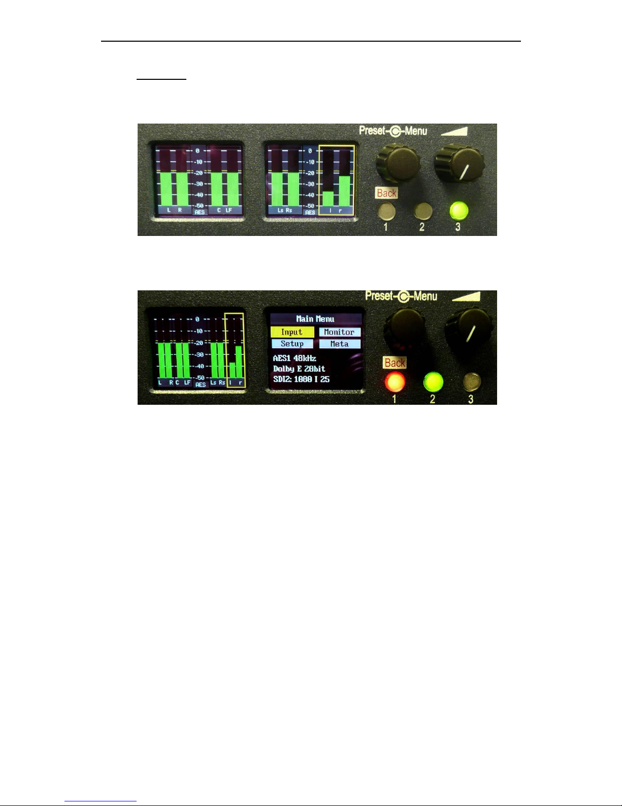
2.1 Controls and Displays
1. The left hand OLED screen displays bargraphs 1-4 in Full-screen mode and bargraphs 1-
8 in Menu mode (shown).
2. The right hand OLED screen displays Bargraphs 5-8 in Full-screen mode, Menu, Preset
and Metadata information in Menu mode (shown). The right hand OLED screen also
displays the Video Confidence Window.
3. The rotary encoder performs multiple functions. Push and rotate actives the „Scroll to
Hear‟ monitoring feature. Push and Release enter the Menu mode. Rotate is used to
recall Factory and User presets.
4. The loudspeaker volume control varies the level of audio to the internal loudspeakers,
external analogue and AES (on D25 connectors when set to Variable mode) and
headphone socket.
5. Hotkey button 3 instantly recalls an assigned User or Factory preset state.
6. Hotkey button 2 instantly recalls an assigned User or Factory preset state. In Menu
mode, button 2 is illuminated green and is used to activate the Save to Preset function.
7. Hotkey button 1 instantly recalls an assigned User or Factory preset state. In Menu
mode, button 1 is illuminated red and is used to scroll Back through the Menu modes.
8. The bargraphs pertaining to the audio being routed to the internal and external
loudspeakers is outlined by the yellow Hear Box.
Page 11
PAM1-3G8 Version 7
2.2 Main Menu
The example below shows PAM1-3G8 in normal dual screen Metering Mode listening to
the LtRt Downmix from a decoded Dolby Digital audio bitstream.
Press the Encoder to access Main Menu. The encoder is then used to highlight and
select from the displayed Menu options. From any Menu, pressing Hotkey 1 (illuminated
red) will exit the current menu page.
The Main Menu screen also displays information about the current selected input signal as
shown in the photo above.
2.2.1 Dolby E Timing and Rate Information
From software version X06, the top level menu of the PAM1-3G8 shows extended
information about any Dolby E sources. This shows the frame rate of the Dolby E
information and its timing relative to a video source where available.
For AES inputs, the frame rate information is displayed as a minimum, eg:
Dolby E 20bit 29.97 - or - Dolby E 16bit 25Hz
For embedded Dolby E sources, the start line position is displayed, eg:
Dolby E 16bit L11
This functionality is also extended to mixed sources. If an AES source is selected for
monitoring, whilst a video source is selected with the same frame rate, then the display will
give the approximate line position of the AES Dolby E start relative to the video. This
allows the timing of an AES signal to be checked either before embedding or after
extraction (note the embedder / extractor delays need to be accounted for in a system).
For sources of different frame rates, the display reverts to the Dolby E frame rate. The
video frame rate is already displayed on the top level menu.
Dolby Digital sources are also identified, although no further information is provided
without a decoder.
All of the above functions are available both with and without on-board Dolby decoding,
providing the source has a correctly formatted SMPTE 337M header
Page 12

PAM1-3G8 Version 7
2.3 Input Selection
By highlighting and selecting the Input option, SDI, AES and Analogue inputs can be
accessed. A shortcut button enables the user to „jump‟ to the Monitor Menu once the
desired input is selected.
2.3.1 SDI Input and Video Confidence Window
Select either SDI Input 1 or 2 and choose which pair of embedded groups is to be
decoded and displayed. Default selection is Group 1 and Group 2, by de-selecting a
group and then selecting another choice, any pair can be decoded.
Note:
If a selected audio pair is encoded with either Dolby E or Dolby Digital, it will be decoded
automatically and the discrete audio stems displayed.
A Video Confidence Window may be displayed on the right hand OLED screen. This
feature is selected and enabled using the Setup Menu as shown on the following screen.
By selecting the Video menu option, the select SDI video source is displayed on the
OLED screen. The Video button allows the user to manually select the input video aspect
ratio. A 16:9 or 4:3 aspect ratio video output to the OLED screen and Downconverted
output is selected using the appropriate DIP switch located at the rear of the unit.
Save your SDI input selection to a User Preset –
See the Using Presets section of this Handbook.
Page 13

PAM1-3G8 Version 7
2.3.2 AES Inputs
Selecting AES simultaneously displays AES inputs 1, 2, 3 and 4.
Note:
If a selected audio pair is encoded with either Dolby E or Dolby Digital, it will be decoded
automatically and the discrete audio stems displayed.
PAM1-3G8 detects the channel coding information of a Dolby E or Dolby Digital
bitstream and identifies the audio stems accordingly (as shown in the example below).
Save your AES input selection to a User Preset –
See the Using Presets section of this Handbook.
2.3.3 Analogue Inputs
Selecting Anlg simultaneously displays stereo Analogue inputs 1 and 2
Page 14

PAM1-3G8 Version 7
2.4 Monitoring and Monitor Menu
The Monitor Menu has been adapted since this Handbook was written and the images
used to describe the menu are partially incorrect. The graphic below shows the revised
Monitor Menu including adapted features described below.
The Monitor Menu includes a „Phase Swap‟ feature which enables the user to reverse the
phase of the right signal of a selected audio pair. In order to accommodate this feature a
fundamental change to mono audio selection functions has been implemented.
The former „Left‟ button now becomes “L – R”. The choice of mode is selected by
pushing the encoder and turning giving „Left‟, „Right‟ and „Swap‟ to stereo outputs. The
function is enabled when highlighted “green)
The former „Right‟ button becomes „Phase‟. When highlighted (green) this reverses the
phase of the selected right audio signal through 180 degrees.
2.4.1 Scroll to Hear
! Introduced on PAM1-3G8 from January 2010 via the X06 software release, the Scroll to
Hear function fundamentally changes the way the navigation encoder works. Within
previous versions the encoder was used to select presets and to activate and navigate
through the PAM1-3G8 menu structure.
Note that the push and rotate action used to implement the „Scroll to Hear‟ feature is now
active within some but not all of the PAM1-3G8 menu pages. Please take time to
familiarise yourself with the new look and feel of PAM1-3G8.
The encoder may be used to move the „Hear Box‟ dynamically across the bargraph
display without reverting to the monitor menu. The operation is described below.
Page 15

PAM1-3G8 Version 7
The Scroll to Hear function can only be activated when the PAM1-3G8 is operating at a
top level view and is inoperative when the menu or metadata screens are active.
Using „Scroll to Hear‟ with Dolby encoded audio
If the source audio pair selected is encoded with a Dolby E or Dolby Digital then the
PAM1-3G8 will automatically decode the signal and display the component parts of the
Dolby signal as soon as the encoder is released. The individual components (as pairs) of
the Dolby signal can then be selected using the „Scroll to Hear‟ function and if the „Hear
Box‟ is scrolled to the right of the bargraph display, then an Lt Rt or Lo Ro Downmix will
be automatically selected and represented on bargraph pair 4.
To deactivate the Dolby encoded screen, simply push and hold the rotary encoder for
more than one second without turning it and the display will revert to display the
associated top level or non decoded audio signals associated with the currently selected
input type.
By highlighting and selecting the Monitor option from the Main Menu, bargraph pairs,
multiple audio stems and downmixes may be routed to the internal and external
loudspeakers.
2.4.2 Mono and Stereo Monitoring (Non Dolby or Discrete Multichannel)
Individual bargraph pairs can be selected from the Monitor Menu as shown below. The
Yellow Hear Box denotes which audio pair is routed to the internal loudspeakers and
headphone socket. Left/Right/Mono options can be chosen so that individual stems can
be isolated or mixed (shown).
Page 16

PAM1-3G8 Version 7
2.4.3 Dolby E or Dolby Digital Monitoring
When a Dolby E or Dolby Digital encoded audio pair is selected, PAM1-3G8 will
automatically decode the signal into its component parts and name the stems according to
the Channel Coding information carried within the Metadata. The Monitor Menu screen
changes dynamically to reflect the selection of a Dolby encoded source and the Monitor
buttons now include options pertinent to the Dolby signal (see below).
A Dolby Lt/Rt (or Lo/Ro if selected via the rear panel DIP switch) option appears and
when selected, a Dolby Downmix is derived by PAM1-3G8 and routed to the
loudspeakers. The Lt/Rt (or Lo/Ro) level is displayed on the 4th bargraph pair (see below).
Dolby monitoring modes allow the user to select to hear individual audio
pairs and stems. The example in the screenshot below shows how to „solo‟ the Centre
Channel and listen to it through the internal or external loudspeakers.
Monitoring using external loudspeakers
De-embedded or decoded multichannel audio (Dolby or discrete PCM) is automatically
routed to the AES and analogue outputs connectors. The rear panel located DIP Switch
includes a selection to mute internal loudspeakers and to set AES and analogue outputs
to variable level (adjusted by the volume control).
Stereo or 5.1 external loudspeakers can be connected (see the application diagram
below).
Dolby E and Dolby Digital
The Dolby monitoring menu includes options called ALL and DRC. When used with a 5.1
loudspeaker monitoring system ALL routes the decoded 5.1 audio to the multichannel
outputs. In DRC mode, the Dolby decoded 5.1 output is affected by Dolby DRC metadata
and adjusted accordingly. If the monitoring mode is switched away from ALL or DRC then
the Centre, Lfe, Ls and Rs speaker channels are muted and only the Left and Right
channels are active. The 5.1 monitoring selections enable a user to „solo‟ individual
surround sound signals to check the integrity of the audio mix.
Page 17

PAM1-3G8 Version 7
Discrete PCM 5.1
The non-Dolby monitoring menu also includes an ALL option. By selecting ALL the
operator can select the group of 6 audios from 2 groups which corresponds to the 5.1
audio signal. Once a 5.1 group has been defined, the 5.1 audio stems are routed to the
external speaker outputs in the correct SMPTE order (L,R,C,Lfe,Ls,Rs). Monitoring
selection options now function similarly to those within the Dolby Menu and include an
ITU775 Downmix option similar to the LtRt mode.
By pressing ALL for a second time (illustrated below), the yellow HEAR box shifts to
highlight an alternative group of 6 audio stems. This function ensures that an embedded
discrete 5.1 signal can be monitored regardless of the location of the 5.1 stems. The user
can store different settings for monitoring discrete 5.1 audio in their User Presets.
The Downmix listening mode is also useful when using the internal loudspeakers to
monitor discrete 5.1 audio channels.
Page 18

PAM1-3G8 Version 7
2.4.4 Internal and External Monitoring Modes
The table below indicates the various monitoring modes available to PAM1-3G8 users and
the audio signals presented to internal loudspeakers and external connectors when each
mode is selected.
M onito ring
M ode Int e rnal LS
Ext F ixed -
D25 (Int LS
On)
Ext F ixed -
D25 (Int LS
Of f )
Ext e rnal
Va riable
Int e rnal LS
Ext F ixed D25 (Int LS
On)
Ext F ixed D25 (Int LS
Of f )
Ext e rnal
Va riable
All Muted Full Full Full Muted Full Full Full
DRC Muted Full Full Full M uted Full Full Full
Lt R t Lt Rt Full
Lt Rt (1st pair
only) 2-4
muted
Lt Rt (1st pair
only) 2-4
muted
N/A N/A N/A N/A
Lo R o Lo Ro Full
Lo Ro (1st pair
only) 2-4
muted
Lo Ro (1st pair
only) 2-4
muted
N/A N/A N/A N/A
DM ix DMix Full
DM ix (1st pair
only) 2-4
muted
DM ix (1st pair
only) 2-4
muted
DM ix Full
DM ix (1st pair
only) 2-4
muted
DM ix (1st pair
only) 2-4
muted
* Individual Individual Full
Indiv. (1st pair
only) 2-4
muted
Indiv. (1st pair
only) 2-4
muted
Individual Full
Indiv. (1st pair
only) 2-4
muted
Indiv. (1st pair
only) 2-4
muted
* Individual refers to single, paired or multiple audio channels selected from the monitoring menu.
Do lby Enco ded Audio
Dis c rete A udio
See 5.1 Loudspeaker Application Diagram on following page
Page 19

PAM1-3G8 Version 7
Page 20

PAM1-3G8 Version 7
2.5 Metadata Menu
Primarily for use with Dolby E and Dolby Digital encoded audio signals, the Metadata
Menu accesses a user selectable group of 7 Dolby Metadata parameters. By highlighting
and selecting any of the 7 options, the user can use the encoder to scroll through a list of
25 commonly used Metadata settings for Dolby E and Dolby Digital audio and create
their own Metadata monitoring view.
Dolby E signals might consist of up to 8 separate programmes (ie: 5.1+2 contains 2
programmes, 2+2+2+2 contains 4 programmes etc) and each programme may be
configured with different Metadata parameters. The Setup Menu allows the user to select
which programme the Metadata is read from. The screen below shows the E prg#
selection on the Setup window. By selecting E prg# the user may scroll through Dolby E
programme numbers 1 to 8 and select the appropriate programme number. This setting
may be saved as part of a user preset.
The example below shows the selection of Dolby E PGM 1 as the default for the Metadata
screen associated with the selected 5.1 audio signal.
The examples below show Metadata displays configured to monitor Dolby Digital and
Dolby E respectively.
Metadata screens can be customised and stored as User Presets.
Page 21

PAM1-3G8 Version 7
2.6 Setup Menu 1 and 2
Setup Menu 1 includes options for different Scales, Reference Levels, Peak Hold,
Dolby E programme, Dolby E Video compensation delay, Video Window, Mix mode
select and Bargraph Styles. By highlighting and selecting a parameter, the user can
scroll through the available options and tailor PAM1-3G8 for their particular application.
2.6.1 Bargraph Settings
The bargraph example below shows a selected EBU Digital scale with -18dBFs reference
level, Peak Hold is „on‟.
The example below shows the previous EBU Digital bargraph scale changed to display a
BBC PPM bargraph.
The dBFS parameter can be used to alter the 0dB reference level from between -12 and 24 dBFS. The Zero parameter selects the offset level between the Zero dBFS setting and
the onset of Peak indication (the point where the bargraph changes colour to red).
When set to Block mode, the Peak parameter enables the user to choose to illuminate the
indication between zero dBFS and the peak level in yellow.
The Hold parameter activates a peak hold indication when switched on.
2.6.2 Dolby E Programme No.
The function of the Dolby E Programme Number selector is described in Section 2.5
2.6.3 Dolby E Video Delay
The PAM1-3G8 features a 1 frame (40 ms) video delay setting which can be inserted
into the Downconverted video display to compensate for the latency caused by decoding
a Dolby E signal. If selected and activated, the delay will be switched into the video signal
path automatically when a Dolby E input signal is detected and decoded. The Video
Confidence window on PAM1-3G8 will be subject to a 1 frame delay when the video
delay mode is active.
Page 22

PAM1-3G8 Version 7
2.6.4 Video Confidence Monitor
The function of the Video Confidence Monitor selector is described in Section 2.3.1
2.6.5 Mixer / Downmix Mode Selector
When monitoring Dolby encoded or discrete surround sound audio, it is often desirable to
listen to a Downmix (stereo fold down) of the multichannel signal. The Mixer / Downmix
Mode Selector activates an ITU-R BS.775-1 Downmix algorithm. The Downmix function
is then made available on the Monitor Menu page for both Dolby and discrete
applications. Where a Dolby encoded signal exists, the Downmix feature offers an
alternative to the Dolby Lt Rt and Lo Ro fold down. In the case of a discrete 5.1 signal,
the Downmix feature can be „toggled‟ between the audio pairs 1/2/3 and pairs 2/3/4 giving
complete flexibility when monitoring embedded signals with multiple audio „programmes‟.
In the example below, a Dolby E signal is Downmixed using the ITU-R BS.775-1
algorithm instead of Dolby Lt Rt.
2.6.6 Setup Menu 2
Setup Menu 2 is used to access the system software page described in Section 2.8 and
also to enable a supervisory user to lock User and Hotkey presets (see Section 2.7.4)
From software version X06 onwards, Setup 2 also provides access to GPI modes as
described.
Page 23

PAM1-3G8 Version 7
2.7 Preset Memories
PAM1-3G8 features 12 Factory and 12 User Programmable Presets, plus 3 Hotkey
buttons for fast save and instant recall of favourite settings.
2.7.1 Factory Presets
Rotating the Encoder counter-clockwise activates the Factory Preset window in the right
hand OLED screen. Highlight and select a preset, PAM1-3G8 will revert to Full Screen
mode displaying the selected audio from the preset list shown below.
1. Last User State
2. HD/SDI Input 1, Group 1 (and 2) Pair 1
3. HD/SDI Input 2, Group 1 (and 2) Pair 1
4. HD/SDI Input 1, Group 2 (and 3) Pair 1
5. HD/SDI Input 2, Group 2 (and 3) Pair 1
6. HD/SDI Input 1, Group 3 (and 4) Pair 1
7. HD/SDI Input 2, Group 3 (and 4) Pair 1
8. HD/SDI Input 1, Group 1 (and 2) Pair 2
9. HD/SDI Input 2, Group 1 (and 2) Pair 2
10. HD/SDI Input 1, Group 2 (and 3) Pair 2
11. HD/SDI Input 2, Group 2 (and 3) Pair 2
12. AES Input
The picture below shows the Factory Preset list followed by the selection of Factory
Preset 1
Factory Presets default to listening to Pair 1. Edit a Factory Preset and save it to a
User Preset.
2.7.2 User Presets
In any Main Menu mode, Button 2 is illuminated Green and can be used to save the
current monitoring condition to one of 12 User Presets. By pressing Button 2 the User
Page 24

PAM1-3G8 Version 7
Preset list is displayed in the right hand OLED screen. The images below show how a
User Preset location may be selected from a Main Menu screen.
Once the Green save button is pressed the User Save menu is activated. Select and
highlight a User Preset location from the list U1 to U12.
The text boxes in the User Save menu can be used to name a User Preset. Up to 18
letters or numbers are available. The example below shows a memory being named as Lt
Rt. Selecting and pressing Done saves the memory to the chosen location.
To recall a User Preset, rotate the Encoder clockwise to activate the User Preset window
in the right hand OLED screen. Highlight and select to recall a User Preset.
Page 25

PAM1-3G8 Version 7
2.7.3 Hotkeys
Hotkeys 1, 2 and 3 can be used to store and recall user settings instantly. By pressing
and holding a Hotkey the current monitoring condition is saved to the Hotkey user
memory. Momentarily pressing a Hotkey recalls a previously stored user memory
instantly.
2.7.4 Locking Presets
Both Hotkey and User Presets can be locked to prevent them from being accidentally
overwritten. To access the Hot and User preset Lock feature the operator must access
Setup Menu 2 as described in Section 2.6
The example below shows the Menu Setup 2 screen followed by the User and Hot save
modes switched to „Lock‟ respectively. When User Lock is activated, the Save button is
deactivated and the User Presets can only be recalled but not edited. Similarly, Hot Lock
prevents the Hot Keys from being overwritten.
Page 26

PAM1-3G8 Version 7
2.8 System Upgrade and CAT552 Reset
PAM1-3G8 is designed to be field upgradeable. The user will need an SD memory card, a
PC and a card reader.
Format the memory card to FAT16 (or FAT as described in Windows XP). The update will
be sent to you by TSL in the form of ZIP file. This must be extracted directly to the
memory card in order to construct the correct file structure for upload.
Once the upgrade file is saved, select the S/Ware function from the PAM1-3G8
Setup menu 2 and view the current FP (front panel) and FPGA software versions.
Press button 1 to exit the S/Ware mode and insert the SD card.
Then re-enter S/Ware mode, a new menu option should have appeared at the
bottom of the screen. Highlight and select Perform Update.
The status of the update is shown by the rising „bargraph‟ as shown below.
Once the update is done, power cycle PAM1-3G8 to complete the procedure.
Page 27

PAM1-3G8 Version 7
The Dolby CAT552 card may need to be reset in the event that it „locks‟. Select the
CAT552 option from the Setup 2 menu and then reset the card.
2.9 GPI Application
The rear panel GPI connector functionality can be used to provide two basic modes of
operation. The Setup 2 menu page now includes a button to access the GPI mode
selector. The operator can choose to set the GPI connector to operate in either „Normal‟
or „Custom1‟ modes.
GPI Mode Application
The two modes of GPI operation are described pictorially by the pin out diagram shown
below.
All of the GPI's other than the preset recalls latch in a toggle manner, i.e. one closure to
ground toggles the function ON; the next ground toggles it OFF. In an ON state; the GPI
pin is driven low to allow an LED to be fed from the port. This LED drive is briefly pulsed
high at about 100Hz to allow the port to be read whilst it is driving.
The preset recall GPI‟s in „Normal‟ are mutually exclusive.
! Note that the +5V power from this connector is intended to drive a "1-of-N" LED. If
multiple LED‟s are to be used simultaneously, then a small external supply will be
needed. An internal resistor within the PAM1-3G8 prevents the +5V rail from being
shorted but limits the current available.
Normal Mode
Page 28

PAM1-3G8 Version 7
Normal mode is intended to enable instant remote recall of user presets 1-4 from an
external manual or automated selector. The ability to remotely Dim or Cut the internal and
external stereo loudspeaker outputs is also featured.
Custom 1 Mode
Custom 1 mode enables remote access to some of the monitor menu features and
additionally the ability to remotely Dim or Cut the internal and external stereo loudspeaker
outputs.
! Note that within GPI mode select, the „Normal‟ operation is the default operational
state. If an operator chooses to use the „Custom1‟ setting he/she must select and save
this mode for each preset saved to memory.
Page 29

PAM1-3G8 Version 7
3.0 Pin-out Details
3.1 Analogue XLR Connectors
C
PIN
FUNCTION
ANALOG 1 1 GND
ANALOG 1 2 1 IN+
ANALOG 1 3 1 IN-
ANALOG 2 1 GND
ANALOG 2 2 2 IN+
ANALOG 2 3 2 IN-
3.2 AES XLR Connectors
C
PIN
FUNCTION
AES1 1 GND
AES 1 2 1 IN+
AES 1 3 1 IN-
AES 2 1 GND
AES 2 2 2 IN+
AES 2 3 2 IN-
3.3 Analogue Output Connector – D25 Socket Pinout on unit, Plug (shown) on mating
cable.
D 25 SOCKET
ON AMU
AUDIO OUTPUTS
PIN NO
FUNCTION
1
A8+ (7.1)
14
A8- (7.1)
2
Ground
15
A7+ (7.1)
3
A7- (7.1)
16
Ground
4
A6+ (RS)
17
A6- (RS)
5
Ground
18
A5+ (LS)
6
A5- (LS)
19
Ground
7
A4+ (LFE)
20
A4- (LFE)
8
Ground
21
A3+ (Centre)
9
A3- (Centre)
22
Ground
10
A2+ (FR)
23
A2- (FR)
11
Ground
24
A1+ (FL)
12
A1- (FL)
25
Ground
13
N/C
Page 30

PAM1-3G8 Version 7
3.4 AES Input/Output Connector – D25 Socket Pinout, Plug (shown) on mating cable.
D 25 SOCKET
ON AMU
AES INPUTS/OUTPUTS
PIN NO
FUNCTION
1
Ch1&2 Input 1+
14
Ch1&2 Input 1-
2
Ch3&4 Input 2+
15
Ch3&4 Input 2-
3
Ch5&6 Input 3+
16
Ch5&6 Input 3-
4
Ch7&8 Input 4+
17
Ch7&8 Input 4-
5
Ch1&2 Output 1+
18
Ch1&2 Output 1-
6
Ch3&4 Output 2+
19
Ch3&4 Output 2-
7
Ch5&6 Output 3+
20
Ch5&6 Output 3-
8
Ch7&8 Output 4+
21
Ch7&8 Output 4-
9
N/C
22
Ground
10
Ground
23
Ground
11
N/C
24
Ground
12
Ground
25
Ground
13
Ground
3.5 DIP switch configuration functions
SWITCH
FUNCTION
1
Video aspect ratio (4:3 Up/16:9 Dn)
2
AES Impedance (75R Up/110R Dn)
3
Internal speaker mute - Up
4
Analogue variable – Up
5
AES variable - Up
6
XLR fixed output (when set)
7
Stereo Mix LoRo Up/Lt Rt Dn
8
Composite Up/SDI Dn
Page 31

PAM1-3G8 Version 7
Notes
There are no user adjustable assemblies/components within this unit.
This unit requires rear support when rack mounted.
In order to affect status changes of the unit using the rear DIP switch, the unit will require re
powering before the changes take effect.
Output analogue levels are adjustable over the following range:
0dBm = 0.775V into 600 i.e. 1mW power dissipation.
0dBu = 0.775V RMS = PPM 4.
Shipping condition, -18 dB ref 0FS = 0dBu output.
Typical European line up: -18 dBu
Typical American line: -20 dBu
5.0 General Notes
Please note that some American equipment has the function of the XLR pins 2 & 3 reversed.
TSL product is wired to the European standard
The screw locks on the D25 connectors use UNC 4-40 standard threads.
6.0 PAM1 - 3G8 Technical Specifications
Power Supply
Supply Voltage 12V DC
Power Consumption 50 watts.
Physical Dimensions
Height 44mm (1RU)
Width 483mm (19”)
Depth 320mm
Weight 6900g
Analogue Inputs 1 - 2
Connector Type XLR Female 3 pin. Pin 1 Gnd, Pin 2 hot, Pin 3 cold.
Signal Balanced line level audio.
Frequency Response 30Hz to 25kHz
Impedance >20k
Inputs AES 1&2
Connector Type XLR Female 3 pin. Pin 1 Gnd, Pin 2 hot, Pin 3 cold.
Standard AES3 (1994) at 48kHz, 44.1kHz or 32kHz
Impedance 110 ohm (balanced.)
Inputs AES 1, 2, 3 & 4 AES I/O, 25 way D type (See section 3.4 for details)
Page 32

PAM1-3G8 Version 7
Input, HD/SDV 1 &2
Connector Type BNC.
Standard 4:2:2 component with embedded 48Khz audio.
(SMPTE 259M, 292M and 424M)
Impedance 75ohm
Line Output.
Connector XLR 3 pin Male
Impedance 50
Output Levels Through level control with 0dB gain.
Fixed Line O/P Available on D25 (If selected on front panel)
Headphone Output.
Connector Stereo Jack socket type A
Impedance 50
Output Levels Through level control with 0dB gain.
De embedded output
Connector 25 way D type
Impedance 110 Ohm
Output Groups 1, 2, 3 and 4
Video Output
Connector BNC
Impedance 75 Ohm
Output Composite video or SDI (selectable)
Re-clocked Output
Connector BNC
Impedance 75 Ohm
Output Re-clocked serial output of the SELECTED input HD/SDV
AES Output
Connector AES I/O, 25 way D type (See section 3.4 for details)
Impedance 110 Ohm
Output Selected SDI Group. decoded Dolby signal or AES I/P 1-
HD Standards Supported
1080i/50 1080p/23.98 1035i/30
1080i/59.94 1080p/24 1035i/29.94
1080i/60 1080p/25 1080sf/30
1080P/50 1080p/29.97 1080sf/29.97
1080P/59.94 1080p/30 1080sf/25
1080P/60 1080i/25 1080sf/24
720p/50 1080i/24.94 1080sf/23.98
720p/59.94 1080i/30
720p/60
480i/30.00 (SD - NTSC)
576i/25.00 (SD - PAL)
Page 33

PAM1-3G8 Version 7
Performance
Response 70Hz to 20KHz
Electrical Distortion Better than 0.1%
Hum and noise Better than -80dB
SPL >98dB at 0.6 m
Amplifier Output 40 watts total power output
Digital Sample Rate 32 to 48KHz auto select
Page 34

PAM1-3G8 Version 7
Installed HDC-2T Audio Monitor Module Specification
Overview
This specification describes the HDC-2T Audio Monitor Module.
This module has been designed to monitor a combination of analogue audio, AES3 digital audio
and AES or Dolby E digital audio embedded in SMPTE 259M or SMPTE 292M video data
streams, together with the video content which is output as composite and/or SDI. HD formats are
passed through a simple down-conversion process to the monitoring output.
Mechanical
PCB: 4 layer, 120mm x 376mm with integral BNC and XLR connectors
Component Height: <30mm above pcb surface, <2mm below
<65mm above pcb surface with Dolby E fitted
Power
The module assumes the supply of regulated power will be made available via the power input
connector. Poorly regulated or noisy supply rails may affect the quality of the analogue outputs.
The HDC-2T will accept two feeds of +12V to +24V DC power, approximately 60W typical when
using loudspeaker outputs. This allows dual redundant or external battery operation.
Inputs
HD/SDI
Connector Type: BNC
Receiver type: AC coupled, auto equalising with clock regeneration
Impedance: 75, return loss ≥15dB to 1.5GHz
Standards: SMPTE 259M-C with embedded 48kHz audio per SMPTE 272M-A
SMPTE 292M with embedded 48kHz audio per SMPTE 299M
Performance: ≥300m of high quality cable at 270Mbit (eg Belden 1694)
≥100m of high quality cable at 1.5Gbit
AES 3 or AES 3id
Connector type: Inputs 1 & 2, XLR 3 pin. (can be built for unbalanced BNC input)
Inputs 1, 2, 3 & 4. 25way D-type 4 stereo pairs, pin-out as per Yamaha
Impedance: 75 unbalanced or 110 balanced. Impedance is switch selected via
DIP Switch 2. To obtain an unbalanced connection one line of the input
needs to be grounded at an electrically convenient point.
Input Sensitivity: < 200mV p-p per AES3.
Standards: AES3-1992 at 96 kHz, 48kHz, 44.1kHz or 32kHz
Analogue Inputs
Connector type: 4 x XLR 3 pin, (Two stereo pairs)
Board header Further 4 stereo pairs (8 channels)
Remote control
Connector type: Header, 10way to connect to 9pin D-type (RS422)
Outputs
Video
Connector Type: BNC
Output 1 Equalised active loop-through
Impedance: 75
Amplitude: 800mV p-p ±10%
Output 2 Composite SD (Down-converted when input is HD)
Format: PAL or NTSC according to standard on SDI input
Impedance: 75
Amplitude: 1V p-p ±5%
Output 3 - Optional SDI version of image on composite output
Impedance: 75
Amplitude: 800mV p-p ±10%
Page 35

PAM1-3G8 Version 7
AES
Four AES (8 channels) may be output from analogue audio, embedded audio or from decoded
Dolby E/D when the option is fitted
Connector type: 25way D-type 4 stereo pairs, pin-out as per Yamaha/Tascam Standard
Impedance: 75 unbalanced or 110 balanced. Impedance is switch selected with
on-board transformer balancing. To obtain an unbalanced connection one
line of the output needs to be grounded at an electrically convenient point.
Amplitude: 1V into 75 or >2V into 110
Analogue Audio
Eight analogue channels (4 stereo pairs) that may be output from AES, embedded audio or from
decoded Dolby E/D when the option is fitted
Connector Type: XLR one pair fixed or variable
25 way D type 4 stereo pairs, pin-out as per Yamaha/Tascam
Format: Electronically balanced, centre ground.
D/A Conversion: 24 bit resolution.
THD+N: >80dB referred to 0dBFS
Loudspeakers
Connector Type: 0.156” board header
Format: Two active cross-over or 4 broad-band loudspeaker outputs
10 to 40W (4) per channel into depending on input power supply
GPI inputs
Connector type: Header to 9-way D-type plug
6.0 Control
Connector type: Header for current AMU-1 operator control board
Connector type: Header, serial bus for future operator control/display panels
 Loading...