

TSL MPA1 Series, MPA1-SOLO-MADI, MPA1-SOLO-SDI, MPA1-MIX-DANTE, MPA1-MIX-MADI Installation And Operation Manual
...Page 1
MPA1 Audio Monitoring Range
Installation and Operation Manual
Version 1.0
Page 2
Page 2 of 72
Version History
Issue
Date
Change Details
1
01/02/18
Preliminary Guide
2
05/10/18
Version 1.0
Page 3
Page 3 of 72
Contents
Introduction .................................................................................................................................................... 5
MPA1-SOLO-SDI Installation ........................................................................................................................... 6
MPA1-SOLO-SDI Functional Schematic ........................................................................................................... 7
MPA1-MIX-SDI Installation ............................................................................................................................. 8
MPA1-MIX-SDI Functional Schematic ............................................................................................................. 9
MPA1-SOLO-MADI Installation .....................................................................................................................10
MPA1-SOLO-MADI Functional Schematic .....................................................................................................11
MPA1-MIX-MADI Installation .......................................................................................................................12
MPA1-MIX-MADI Functional Schematic .......................................................................................................13
MPA1-SOLO-DANTE Installation ...................................................................................................................14
MPA1-SOLO-DANTE Functional Schematic ...................................................................................................15
MPA1-MIX-DANTE Installation .....................................................................................................................16
MPA1-MIX-DANTE Functional Schematic .....................................................................................................17
Initial Setup ...................................................................................................................................................18
Accessing the Webpage of your MPA1 .........................................................................................................19
MPA1-SOLO-SDI Webpage ............................................................................................................................20
MPA1-SOLO-MADI Web Page .......................................................................................................................24
MPA1-SOLO-DANTE Web Page .....................................................................................................................28
MPA1-MIX-SDI Web Page .............................................................................................................................32
MPA1-MIX-MADI Web Page .........................................................................................................................39
MPA1-MIX-DANTE Web Page .......................................................................................................................46
Operation ......................................................................................................................................................53
MPA1-SOLO-SDI Operation ...........................................................................................................................54
MPA1-SOLO-MADI Operation .......................................................................................................................55
MPA1-SOLO-DANTE Operation .....................................................................................................................56
MPA1-MIX-SDI Operation .............................................................................................................................57
MPA1-MIX-MADI Operation .........................................................................................................................59
MPA1-MIX-DANTE Operation .......................................................................................................................61
MPA1-SOLO-SDI Front Panel Display ............................................................................................................63
MPA1-MIX-SDI Front Panel Display ..............................................................................................................65
MPA1-SOLO-MADI Front Panel Display ........................................................................................................66
MPA1-MIX-MADI Front Panel Display ..........................................................................................................68
MPA1-SOLO-DANTE Front Panel Display ......................................................................................................69
MPA1-MIX-DANTE Front Panel Display ........................................................................................................71
Page 4

Page 4 of 72
Page 5
Page 5 of 72
Introduction
The MPA1 Range of Audio Monitors provide high-quality confidence monitoring in a compact 1RU design.
At just 100mm deep and less than 4kg, MPA1 Audio Monitors are ideally suited for environments where
space and weight is a premium, such as OB Trucks and Flyaways.
Designed for ease of use, all MPA1 Audio Monitors can be controlled directly from the front panel, or
remotely over an Ethernet network using a suitable Web-Browser or control system using SNMP.
This manual covers the following Audio Monitoring Products within the MPA1 Range:
The MPA1-SOLO variants provide instantaneous selection and monitoring of any incoming audio source,
whilst the MPA1-MIX variants also allow for multiple monitor mixes, comprising up to 8 audio pairs, to be
created, stored and recalled with ease.
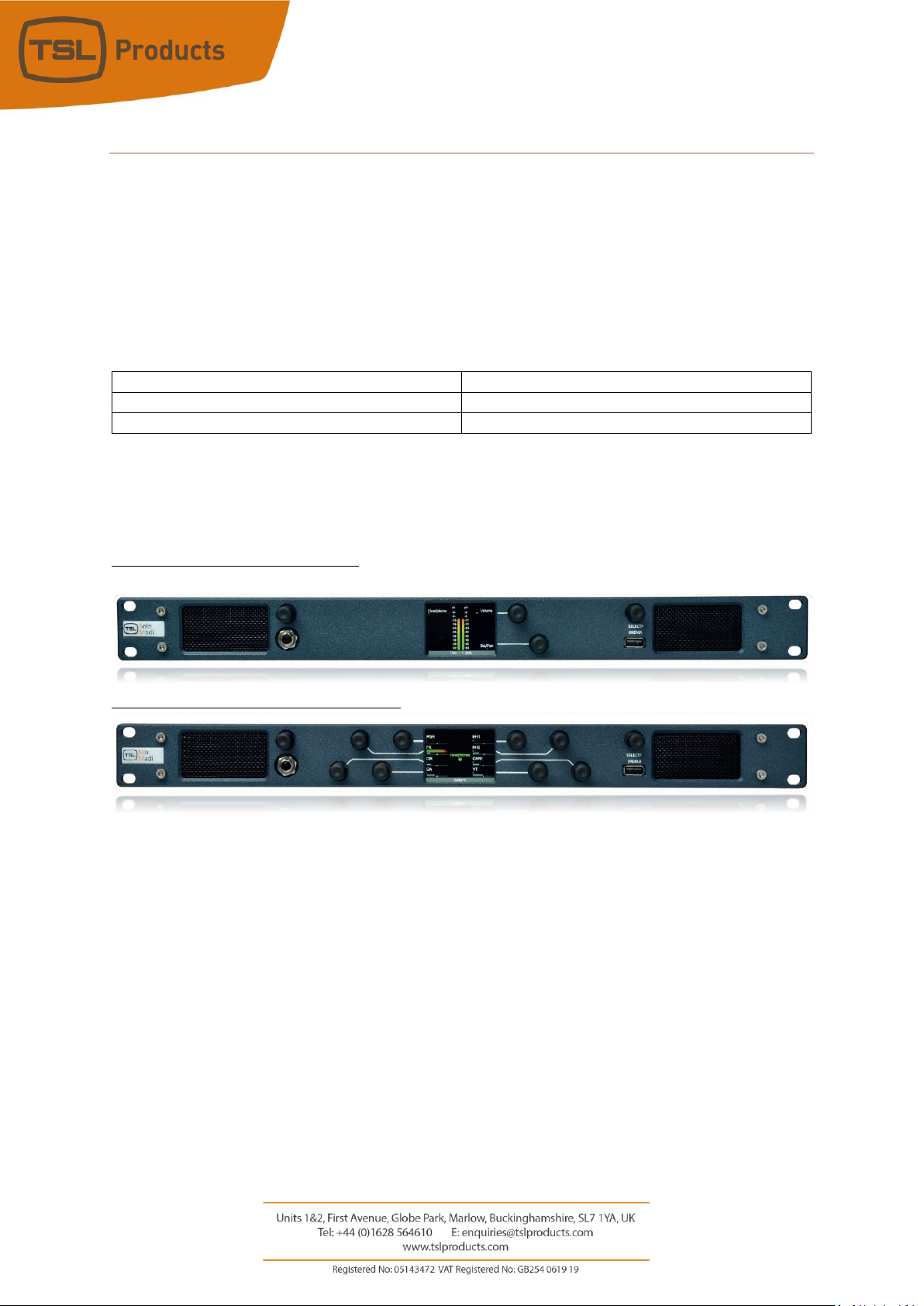
Front Panel for MPA1-SOLO Variants
Front Panel Layout for MPA1-MIX-Variants
MPA1-SOLO-SDI
MPA1-MIX-SDI
MPA1-SOLO-MADI
MPA1-MIX-MADI
MPA1-SOLO-DANTE
MPA1-MIX-DANTE
Page 6

Page 6 of 72
MPA1-SOLO-SDI Installation
The MPA1 Audio Monitoring Range has been designed to be quick and easy to install, requiring minimal
installation effort. Input and output connectivity for each MPA1 Model can be seen below:
MPA1-SOLO-SDI
Product
Inputs
Outputs
Other
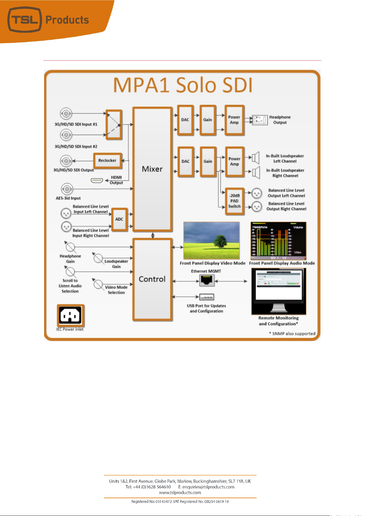
MPA1-SOLO-SDI
2 x 3G/HD/SD-SDI
1 x AES3 (75 ohm)
2 x Analogue Inputs
(Balanced)
1 x 3G/HD/SD-SDI
(reclocked)
2 x Analogue Outputs
(Balanced)
1 x Headphone Output
1 x HDMI Monitoring
Output
1 x 1Gig/E Ethernet
Port (Management and
Control)
1 x USB Port (Software
Updates and
Configuration)
1 x IEC Power Inlet
Page 7
Page 7 of 72
MPA1-SOLO-SDI Functional Schematic
Page 8

Page 8 of 72
MPA1-MIX-SDI Installation
The MPA1 Audio Monitoring Range has been designed to be quick and easy to install, requiring minimal
installation effort. Input and output connectivity for each MPA1 Model can be seen below:
MPA1-MIX-SDI
Product
Inputs
Outputs
Other
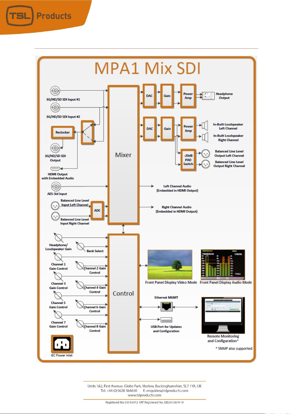
MPA1-MIX-SDI
2 x 3G/HD/SD-SDI
1 x AES3 (75 ohm)
2 x Analogue Inputs
(Balanced)
1 x 3G/HD/SD-SDI
(reclocked)
2 x Analogue Outputs
(Balanced)
1 x Headphone Output
1 x HDMI Monitoring
Output
1 x 1Gig/E Ethernet
Port (Management and
Control)
1 x USB Port (Software
Updates and
Configuration)
1 x IEC Power Inlet
Page 9
Page 9 of 72
MPA1-MIX-SDI Functional Schematic
Page 10
Page 10 of 72
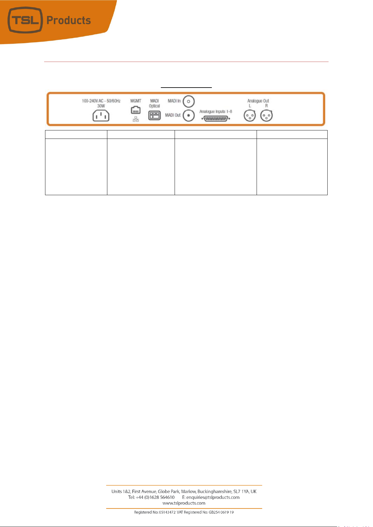
MPA1-SOLO-MADI Installation
MPA1-SOLO-MADI
Product
Inputs
Outputs
Other
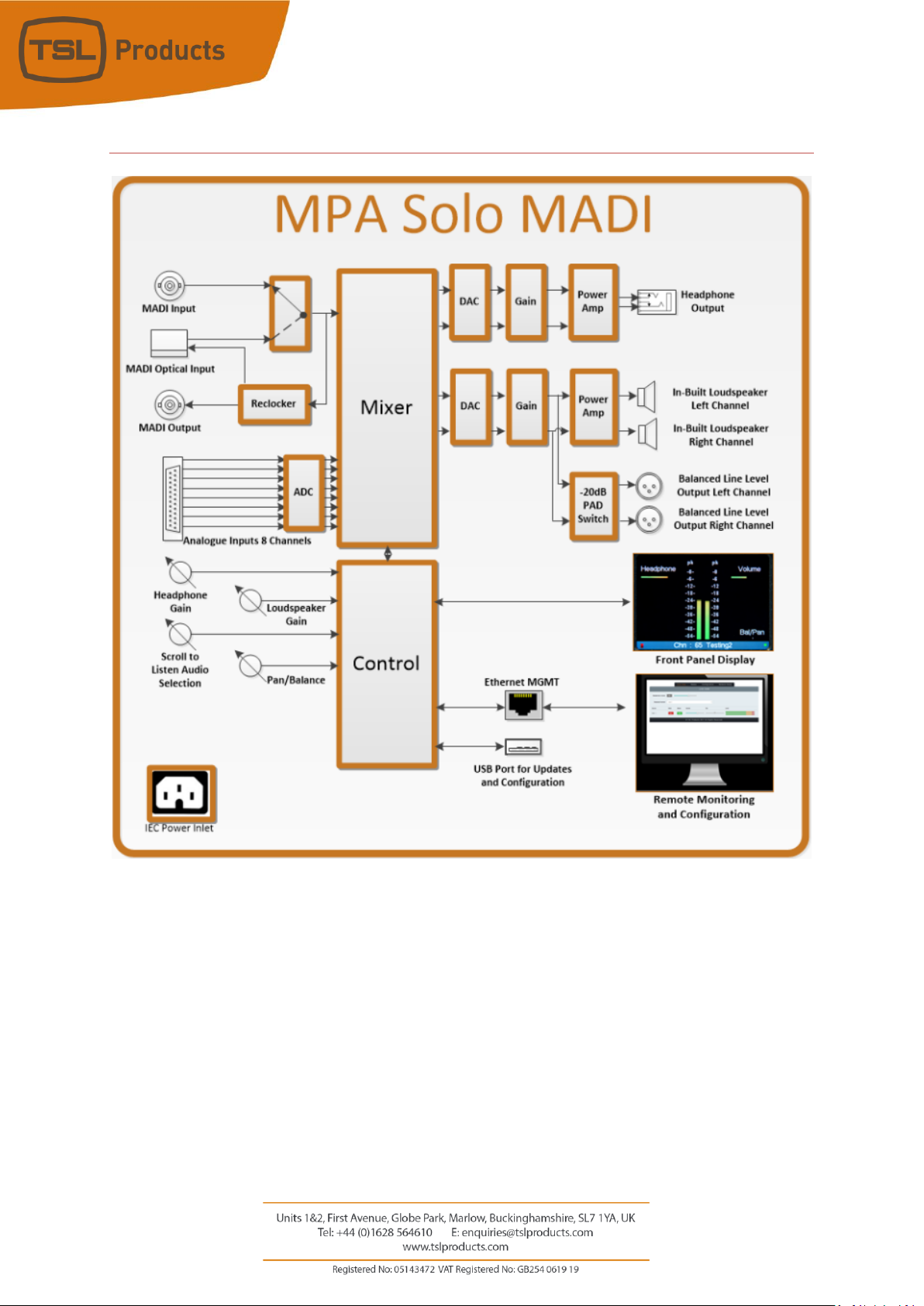
MPA1-SOLO-MADI
1 x MADI (75 ohm)
1 x MADI (SFP cage for
optional SFP module)
8 x Analogue Inputs
(Balanced)
1 x MADI (75 ohm)
reclocked
2 x Analogue Outputs
(Balanced)
1 x Headphone Output
1 x 1Gig/E Ethernet
Port (Management and
Control)
1 x USB Port (Software
Updates and
Configuration)
1 x IEC Power Inlet
Page 11
Page 11 of 72
MPA1-SOLO-MADI Functional Schematic
Page 12

Page 12 of 72
MPA1-MIX-MADI Installation
MPA1-MIX-MADI
Product
Inputs
Outputs
Other
MPA1-MIX-MADI
1 x MADI (75 ohm)
1 x MADI (SFP cage for
optional SFP module)
8 x Analogue Inputs
(Balanced)
1 x MADI (75 ohm)
reclocked
2 x Analogue Outputs
(Balanced)
1 x Headphone Output
1 x 1Gig/E Ethernet
Port (Management and
Control)
1 x USB Port (Software
Updates and
Configuration)
1 x IEC Power Inlet
Page 13
Page 13 of 72
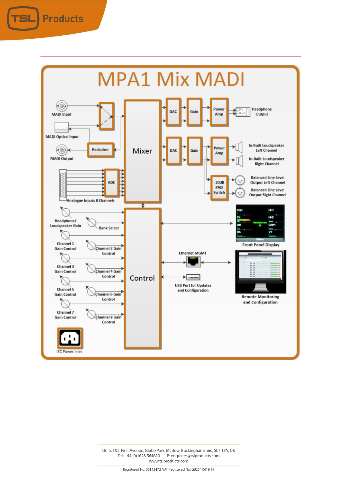
MPA1-MIX-MADI Functional Schematic
Page 14
Page 14 of 72
MPA1-SOLO-DANTE Installation
MPA1-SOLO-DANTE
Product
Inputs
Outputs
Other
MPA1-SOLO-DANTE
1 x 1Gig/E Ethernet
Port (Dante/AES67)
1 x MADI (75 ohm)
1 x MADI (SFP cage for
optional SFP module)
8 x Analogue Inputs
(Balanced)
1 x MADI (75 ohm)
reclocked
2 x Analogue Outputs
(Balanced)
1 x Headphone Output
1 x 1Gig/E Ethernet
Port (Management and
Control)
1 x USB Port (Software
Updates and
Configuration)
1 x IEC Power Inlet
Page 15
Page 15 of 72
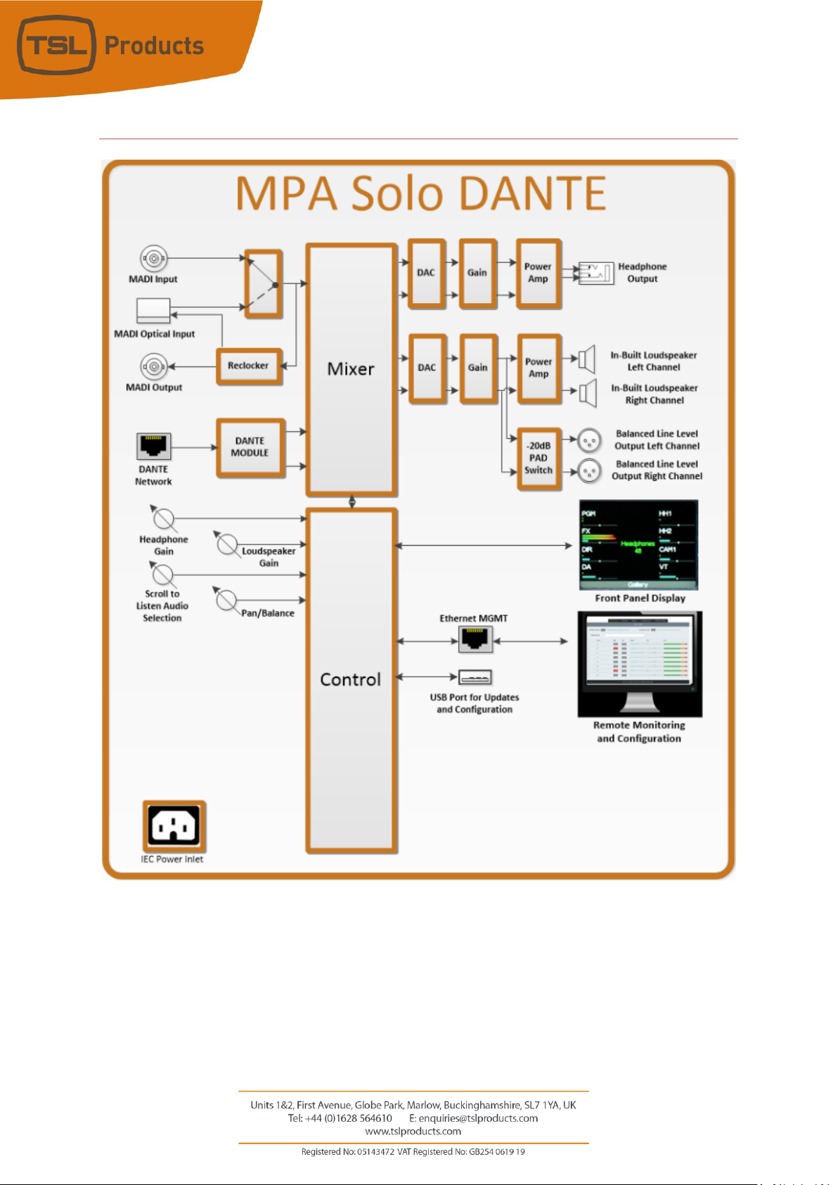
MPA1-SOLO-DANTE Functional Schematic
Page 16

Page 16 of 72
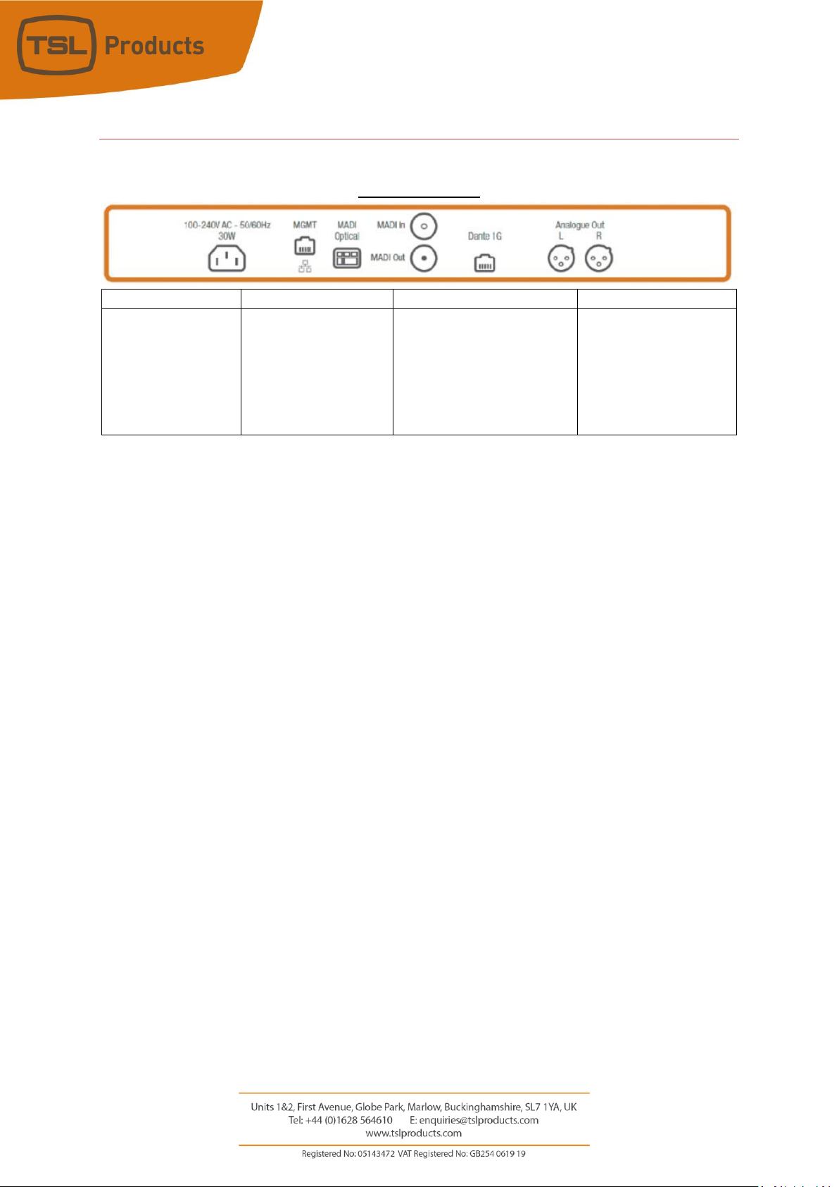
MPA1-MIX-DANTE Installation
MPA1-MIX-DANTE
Product
Inputs
Outputs
Other
MPA1-MIX-DANTE
1 x 1Gig/E Ethernet
Port (Dante/AES67)
1 x MADI (75 ohm)
1 x MADI (SFP cage for
optional SFP module)
8 x Analogue Inputs
(Balanced)
1 x MADI (75 ohm)
reclocked
2 x Analogue Outputs
(Balanced)
1 x Headphone Output
1 x 1Gig/E Ethernet
Port (Management and
Control)
1 x USB Port (Software
Updates and
Configuration)
1 x IEC Power Inlet
Page 17

Page 17 of 72
MPA1-MIX-DANTE Functional Schematic
Page 18
Page 18 of 72
Initial Setup
TSL Products recommends connecting your MPA1 Audio Monitor to an Ethernet network during initial setup and configuration.
Full configuration of your MPA1 Audio Monitor can be achieved by way of a suitable Client PC and Webbrowser.
Setting the Control IP Address of your MPA1 Audio Monitor
All MPA1 Audio Monitors are shipped with a DHCP setting default to ‘DHCP ‘On’.
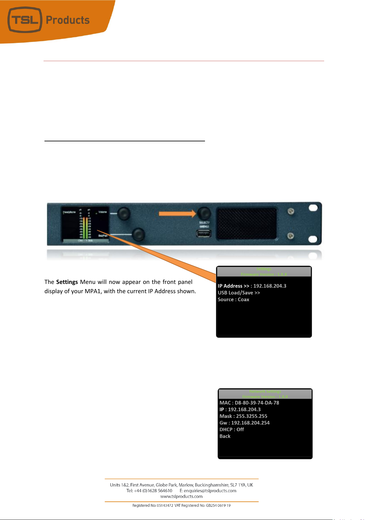
To determine the current IP address of your MPA1, push and hold the SELECT/MENU encoder for 3 seconds
to access the Settings Menu.
The Settings Menu will now appear on the front panel
display of your MPA1, with the current IP Address shown.
Using the SELECT/MENU encoder, you can scroll through the
Settings Menu to highlight a Settings Sub-Menu of your choice.
The availability of Sub-Menus is depicted by the presence of the
following symbol: >>
With the IP Address Sub-Menu highlighted as shown, briefly push the SELECT/MENU encoder to access the
Network Settings Menu (see below).
The SELECT/MENU encoder will now allow you to scroll through,
select and modify the Network Settings of your MPA1 in
accordance with the guidelines set by your Network
Administrator.
Once complete, select BACK to return to the Settings Menu. You
can exit the Settings Menu by pushing and holding the
SELECT/MENU encoder for 3 seconds once more.
Page 19
Page 19 of 72
Accessing the Webpage of your MPA1
Configuring your MPA1 Audio Monitor using a Client PC and Web-Browser
With your MPA1 connected to an Ethernet network, you can remotely control and configure your MPA1
using a Client PC and Web-Browser.
The MPA1 Webpage allows you to optimise your MPA1 for your environment and the workflow you need
to support.
Settings such as the brightness of the front panel display, which sources may be selected from the front
panel of the unit and the behaviour of the MPA1 when used with Headphones can all be set using the
MPA1 Webpage.
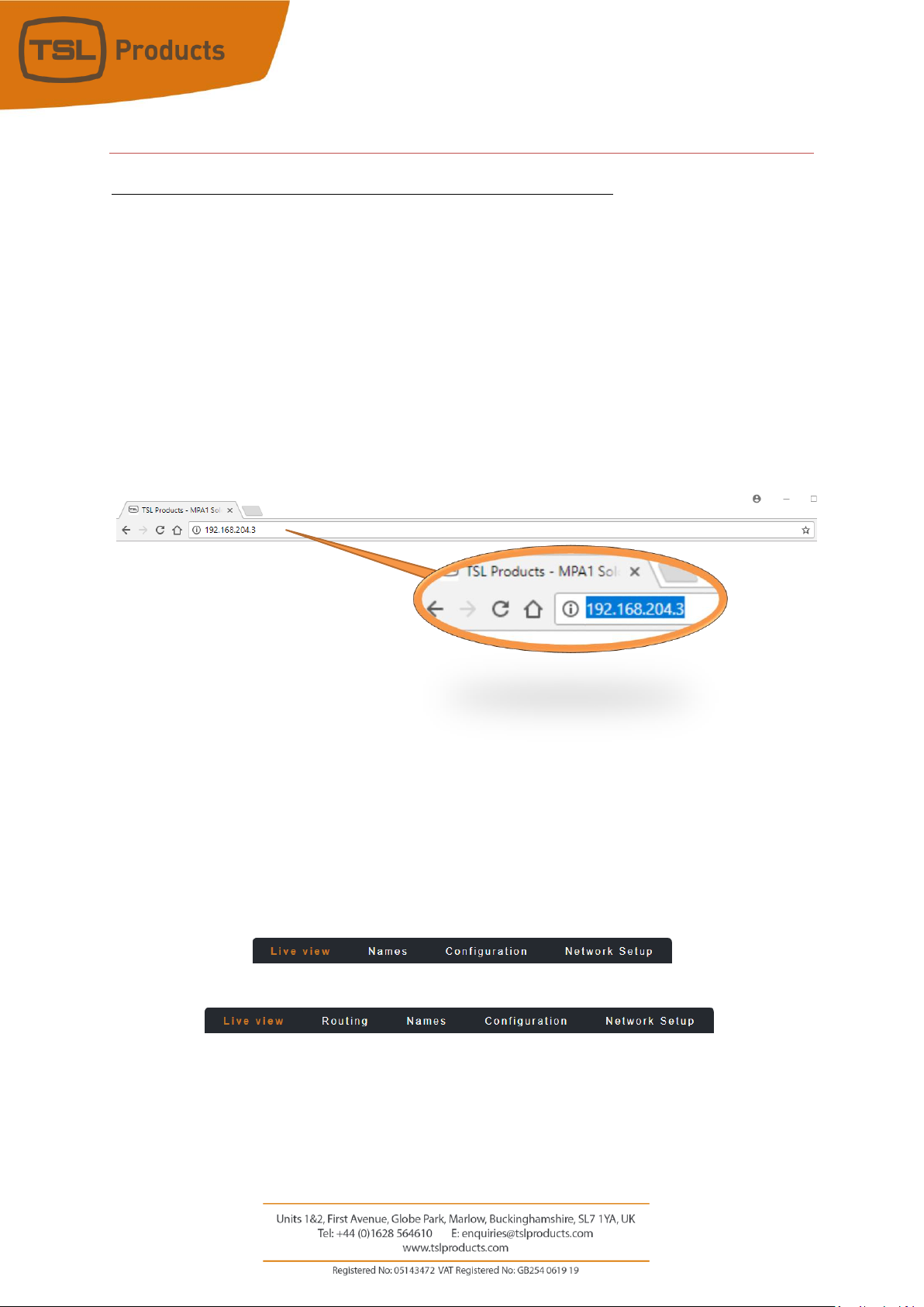
Enter the IP Address of your MPA1 into a Web-Browser
The MPA1 Webpage comprises multiple Tabs, providing quick navigation to specific sections of the MPA1
configuration, providing quick and easy setup.
Separate Tabs for LIVE VIEW, NAMES, CONFIGURATION and NETWORK SETUP are present on the Webpage
belonging to all MPA1-SOLO variants, whilst an extra ROUTING Tab can be found on all MPA1-MIX variants.
MPA1-SOLO- SDI, MPA1-SOLO-MADI and MPA1-SOLO-DANTE
MPA1-MIX- SDI, MPA1-MIX-MADI and MPA1-MIX-DANTE
The following pages detail the contents and settings available using the MPA1 Model.
Page 20
Page 20 of 72
MPA1-SOLO-SDI Webpage
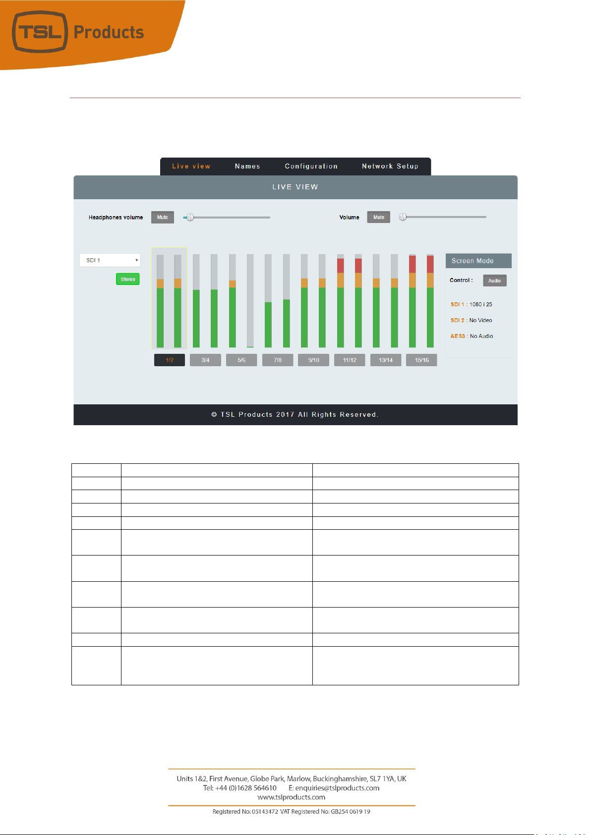
Clicking on the LIVE VIEW Tab of the MPA1-SOLO-SDI Webpage displays the following:
Element
Function
Notes
1
Switch to Mute Headphone Output
Red when Muted, Grey when Active
2
Headphone Output Level adjustment
Adjust as required
3
Switch to Mute the Loudspeaker Output
Red when Muted, Grey when Active
4
Loudspeaker Output Level adjustment
Adjust as required
5
Input Selection
Switches between SDI 1, SDI 2 and AES +
Analogue Input Monitoring
6
Audio Level Meter Display
Displays Audio Levels in accordance with Input
Selection
7
Stereo/Mono Switch
Switches Audio Monitoring Selectors between
Single Audio Channel and Audio Pair mode.
8
Screen Mode Switch
Switches front panel display between Audio
Metering and SDI Video Source.
9
Signal Format Display
Format display of SDI 1, SDI 2 and AES3 Inputs
10
Audio Monitor Selectors
Selects the Single Audio Channel or Audio Pair
routed to the Headphone and Loudspeaker
Outputs.
1
2 3 4 5 7
10 6 8
9
Page 21
Page 21 of 72
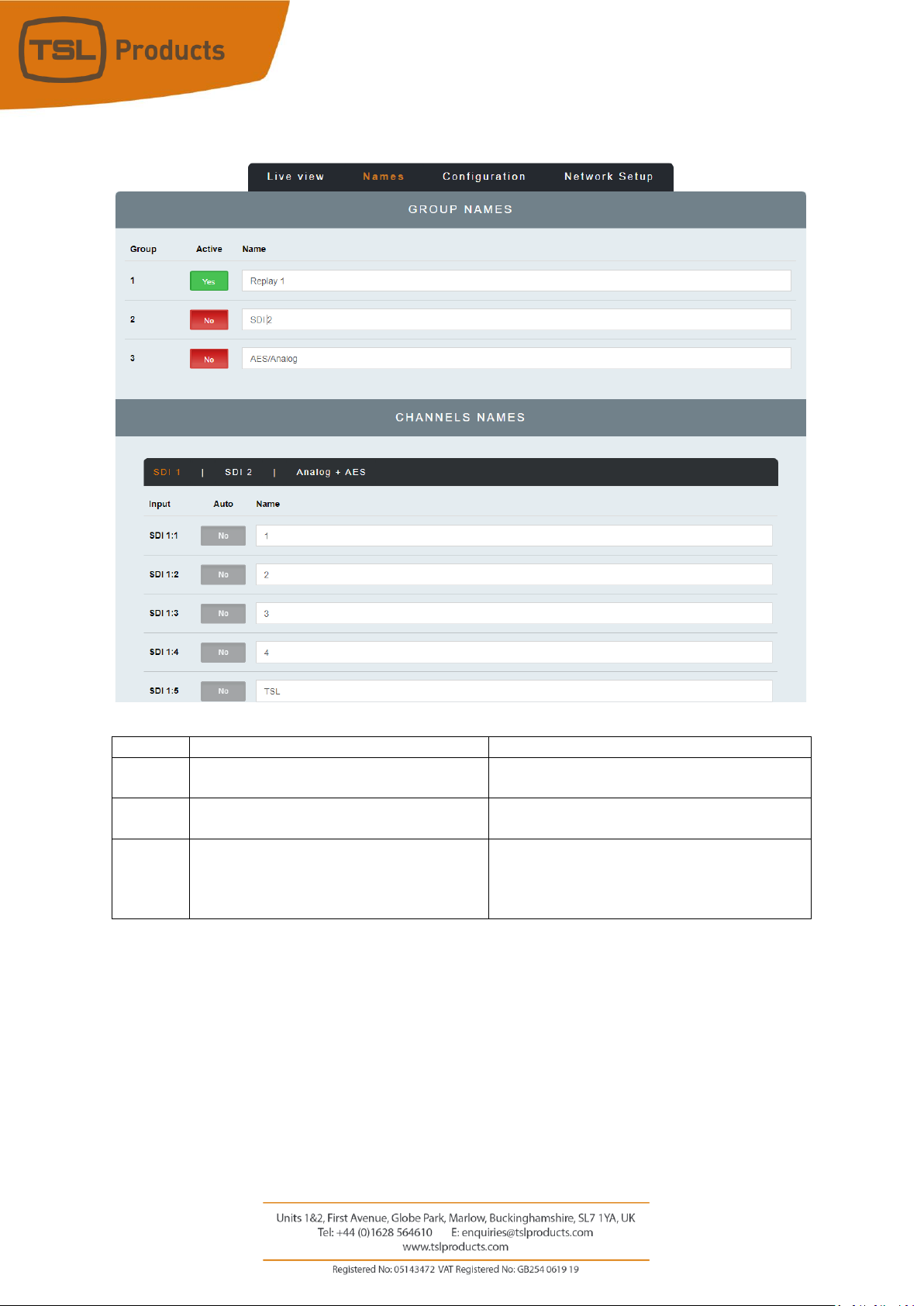
Clicking on the NAMES Tab of the MPA1-SOLO-SDI Webpage displays the following:
Element
Function
Notes
1
Input Active Buttons
Allows unused inputs to be hidden from the
Operator
2
Input Names
Allows friendly names to be applied to SDI 1,
SDI 2 and AES/Analog Input Groups
3
Channel Names
Allows friendly names to be applied to all 16
Embedded Audio Channels belonging to SDI 1
and SDI 2 Inputs and AES and Analogue
Channels.
1 2 3
Page 22
Page 22 of 72
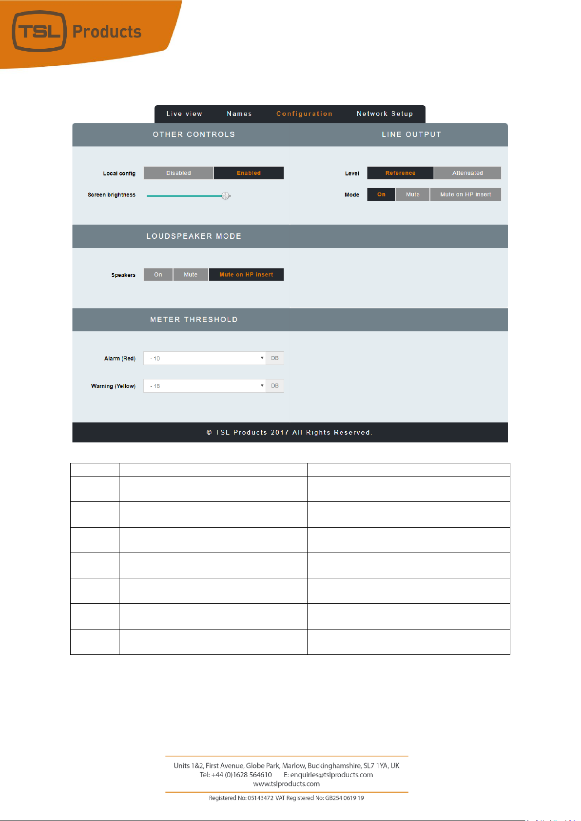
Clicking on the CONFIGURATION Tab of the MPA1-SOLO-SDI Webpage displays the following:
Element
Function
Notes
1
Local Config
Enables/Disables configuration from the front
panel of the MPA1-SOLO-SDI
2
Line Output Level
Sets the Output Level of the Balanced Line
Level Outputs on the MPA1-SOLO-SDI
3
Screen Brightness
Sets the Brightness Level of the front panel
display
4
Line Output Mode
Determines behaviour of Balanced Line Level
Outputs upon insertion of Headphones.
5
Loudspeaker Mode
Determines behaviour of Internal
Loudspeakers upon insertion of Headphones.
6
Meter Threshold RED
Sets audio threshold at which audio level
meters begin to display RED
7
Meter Threshold YELLOW
Sets audio threshold at which audio level
meters begin to display YELLOW
1 3 2 4 5 6 7
Page 23

Page 23 of 72
Clicking on the NETWORK SETTINGS Tab of the MPA1-SOLO-SDI Webpage displays the following:
Element
Function
Notes
1
DHCP
Enables/Disables DHCP Mode
2
IP Address
Displays current IP Address and allows new IP
Address to be entered.
3
Subnet Mask
Displays current Subnet Mask and allows new
Subnet Mask to be entered.
4
Gateway Address
Displays current Gateway Address and allows
new Gateway Address to be entered.
5
Apply IP Address
Button to apply IP, Subnet and Gateway
addresses to the MPA1-SOLO-SDI
1 2 3
4
5
Page 24

Page 24 of 72
MPA1-SOLO-MADI Web Page
Clicking on the LIVE VIEW Tab of the MPA1-SOLO-MADI Webpage displays the following:
Element
Function
Notes
1
Switch to Mute Headphone Output
Red when Muted, Grey when Active
2
Headphone Output Level adjustment
Adjust as required
3
Displayed Channel
Drop down list allowing Input selection of
MADI Sources 1-64 and Analog Sources 1-8.
4
Source Name
Displays friendly name of selected source as
entered in NAMES Tab.
5
Mute Switch
Mutes Headphone, Internal Loudspeakers and
Balanced Line Level Outputs.
6
Stereo/Mono Switch
Switches between Mono and Stereo
monitoring modes.
7
Source Volume
Adjusts Internal Loudspeaker and Balanced
Line Level Outputs.
8
Pan
Pan control of selected source on Headphone,
Internal Loudspeakers and Balanced Line Level
Outputs.
9
Audio Level Meter Display
Displays Audio Levels in accordance with Input
Selection
1 2 3 4 5 6 7 8 9
Page 25

Page 25 of 72
Clicking on the NAMES Tab of the MPA1-SOLO-MADI Webpage displays the following:
…
Element
Function
Notes
1
MADI/Analogue Channel Number
2
Source Channel Names
Allows friendly names to be applied to MADI
Channels 1-64 and Analogue Channels 1-8*
* Please note that the Auto Naming function is fixed to NO on the MP1-SOLO-MADI
1
2
Page 26

Page 26 of 72
Clicking on the CONFIGURATION Tab of the MPA1-SOLO-MADI Webpage displays the following:
Element
Function
Notes
1
Local Config
Enables/Disables configuration from the front
panel of the MPA1-SOLO-MADI
2
Line Output Level
Sets the Output Level of the Balanced Line
Level Outputs on the MPA1-SOLO-MADI
3
Screen Brightness
Sets the Brightness Level of the front panel
display
4
Line Output Mode
Determines behaviour of Balanced Line Level
Outputs upon insertion of Headphones.
5
Source I/O
Switch to set whether the Coaxial BNC or
Optical SFP input is to be used to receive MADI
6
Loudspeaker Mode
Determines behaviour of Internal
Loudspeakers upon insertion of Headphones.
1 2 3 4 5
6
Page 27

Page 27 of 72
Clicking on the NETWORK SETTINGS Tab of the MPA1-SOLO-MADI Webpage displays the following:
Element
Function
Notes
1
DHCP
Enables/Disables DHCP Mode
2
IP Address
Displays current IP Address and allows new IP
Address to be entered.
3
Subnet Mask
Displays current Subnet Mask and allows new
Subnet Mask to be entered.
4
Gateway Address
Displays current Gateway Address and allows
new Gateway Address to be entered.
5
Apply IP Address
Button to apply IP, Subnet and Gateway
addresses to the MPA1-SOLO-MADI
1 2 3
4
5
Page 28

Page 28 of 72
MPA1-SOLO-DANTE Web Page
Clicking on the LIVE VIEW Tab of the MPA1-SOLO-DANTE Webpage displays the following:
Element
Function
Notes
1
Switch to Mute Headphone Output
Red when Muted, Grey when Active
2
Headphone Output Level adjustment
Adjust as required
3
Displayed Channel
Drop down list allowing Input selection of
DANTE Sources 1-64 and MADI Sources 1-64
4
Source Name
Displays friendly name of selected source as
entered in NAMES Tab.
5
Mute Switch
Mutes Headphone, Internal Loudspeakers and
Balanced Line Level Outputs.
6
Stereo/Mono Switch
Switches between Mono and Stereo
monitoring modes.
7
Source Volume
Adjusts Internal Loudspeaker and Balanced
Line Level Outputs.
8
Pan
Pan control of selected source on Headphone,
Internal Loudspeakers and Balanced Line Level
Outputs.
9
Audio Level Meter Display
Displays Audio Levels in accordance with Input
Selection
1 2 5 6 7 8 9 4 3
Page 29

Page 29 of 72
Clicking on the NAMES Tab of the MPA1-SOLO-DANTE Webpage displays the following:
…
Element
Function
Notes
1
DANTE/MADI Channel Number
2
Source Channel Names
Allows friendly names to be applied to DANTE
Channels 1-64 and MADI Channels 1-64*
* Please note that the Auto Naming function is fixed to NO on the MP1-SOLO-MADI for MADI
Sources. When Auto Naming is set to ‘YES’ for DANTE sources, friendly names will be ignored,
with Source Names as set in DANTE Controller
Clicking on the CONFIGURATION Tab of the MPA1-SOLO-DANTE Webpage displays the following:
1
2
Page 30

Page 30 of 72
Element
Function
Notes
1
Local Config
Enables/Disables configuration from the front
panel of the MPA1-SOLO-DANTE
2
Line Output Level
Sets the Output Level of the Balanced Line
Level Outputs on the MPA1-SOLO-DANTE
3
Screen Brightness
Sets the Brightness Level of the front panel
display
4
Line Output Mode
Determines behaviour of Balanced Line Level
Outputs upon insertion of Headphones.
5
Source I/O
Switch to set whether the Coaxial BNC or
Optical SFP input is to be used to receive MADI
6
Loudspeaker Mode
Determines behaviour of Internal
Loudspeakers upon insertion of Headphones.
Clicking on the NETWORK SETTINGS Tab of the MPA1-SOLO-MADI Webpage displays the following:
1 2 3
4 5 6
Page 31

Page 31 of 72
Element
Function
Notes
1
DHCP
Enables/Disables DHCP Mode
2
IP Address
Displays current IP Address and allows new IP
Address to be entered.
3
Subnet Mask
Displays current Subnet Mask and allows new
Subnet Mask to be entered.
4
Gateway Address
Displays current Gateway Address and allows
new Gateway Address to be entered.
5
Apply IP Address
Button to apply IP, Subnet and Gateway
addresses to the MPA1-SOLO-MADI
1 2 3
4
Page 32

Page 32 of 72
MPA1-MIX-SDI Web Page
Clicking on the LIVE VIEW Tab of the MPA1-MIX-SDI Webpage displays the following:
Element
Function
Notes
1
Switch to Mute Headphone Output
Red when Muted, Grey when Active
2
Headphone Output Level adjustment
Adjust as required
3
Switch to Mute the Loudspeaker Output
Red when Muted, Grey when Active
4
Loudspeaker Output Level adjustment
Adjust as required
5
Mix Bank Selection
Drop down list allowing recall of one of 16
Audio Mix Banks (A-P)
6
Display
Switches Front Panel Display of MPA1-MIX-SDI
between Audio Meters and SDI Video Source
7
Source Name
Displays Source and Friendly Name*
8
Channel Mute
Mutes Selected Channel
9
Channel Solo
Places Selected Channel in Solo Mode (Click
and Hold)
10
Channel Volume
Adjusts channel Volume within overall Mix
11
Channel Pan
Adjusts channel Pan within overall Mix
12
Audio Level Meters
Audio Level Display
* Friendly Names can be set in the NAMES Tab
1 2 3 4 5 6 7 8 9
10
11
12
Page 33

Page 33 of 72
Clicking on the ROUTING Tab of the MPA1-MIX-SDI Webpage displays the following:
…
Element
Function
Notes
1
Mix Bank Identifier
Identifies one of the 16 Mix Banks (A-P)
2
Channel Number
Channel number of source contributing to Mix
Bank (1-8)
3
Audio Channel Gain Preset
Allows +20dB, +10db, 0dB, -10dB or -20dB to
be applied to Audio Channel Input
4
Stereo/Mono Switch
Switches Input Channel between Audio
Channel and Audio Pair Mode
5
Audio Channel Selector
Selects Audio Channels contributing to chosen
Mix Bank. Audio Channels Embedded in SDI 1,
SDI 2 and AES and Analogue Inputs can be
selected.
2 3 1
2
4
5
Page 34

Page 34 of 72
Clicking on the NAMES Tab of the MPA1-MIX-SDI Webpage displays the following:
…
…
…
1 2 3 4 5 6 7
Page 35

Page 35 of 72
Element
Function
Notes
1
Mix Bank Identifier
Identifies one of the 16 Mix Banks (A-P)
2
Active Switch
Determines which MIX Banks are available for
selection on the front panel of the MPA1-MIXSDI.
3
Video Switch
Determines which SDI Video Source is
displayed on the front panel, reclocked SDI
Output and HDMI Output for each MIX Bank
4
Mix Bank Name
Friendly Name of MIX Bank*
5
Physical Input Identifier
Physical Input and Channel Number
6
Auto Naming Function
Not Supported
7
Friendly Name
Allows friendly names to be applied to SDI
Embedded Audio, AES and Analogue Audio
Channels
Page 36

Page 36 of 72
Clicking on the CONFIGURATION Tab of the MPA1-MIX-SDI Webpage displays the following:
Element
Function
Notes
1
Channel Knob Push
Enables/Disables ‘Push to Mute’ function of
Channel Rotary Encoders on front panel of
MPA1-MIX-SDI
2
Channel Knob Push and Rotate
Determines ‘Push and Rotate’ behaviour of
Channel Rotary Encoders on the front panel of
the MPA1-MIX-SDI. When set to Balance, the
Audio Balance of the selected Audio Channel
can be adjusted. When set to Mapping, the
Physical Audio Channel assigned to the Mix
Channel can be selected.
3
Channel Knob Push and Hold
Enables/Disables ‘Push and Hold to Solo’
function of Channel Rotary Encoders on front
panel of MPA1-MIX-SDI
4
Input Status
Displays the Status and Signal Format of SDI
and AES Sources
5
Gain Bar Display
Enables/Disables the Gain Bar Display from the
front panel of the MPA1-MIX-SDI.
6
Local Config
Enables/Disables configuration from the front
panel of the MPA1-MIX-SDI
7
Line Output Level
Sets the Output Level of the Balanced Line
Level Outputs on the MPA1-MIX-SDI
8
Line Output Mode
Determines behaviour of Balanced Line Level
Outputs upon insertion of Headphones.
1 2 3 4 5 6 9 7 8
10
Page 37

Page 37 of 72
9
Screen Brightness
Sets the Brightness Level of the front panel
display
10
Loudspeaker Mode
Determines the behaviour of Internal
Loudspeakers upon insertion of Headphones
Page 38

Page 38 of 72
Clicking on the NETWORK SETTINGS Tab of the MPA1-MIX-SDI Webpage displays the following:
Element
Function
Notes
1
DHCP
Enables/Disables DHCP Mode
2
IP Address
Displays current IP Address and allows new IP
Address to be entered.
3
Subnet Mask
Displays current Subnet Mask and allows new
Subnet Mask to be entered.
4
Gateway Address
Displays current Gateway Address and allows
new Gateway Address to be entered.
5
Apply IP Address
Button to apply IP, Subnet and Gateway
addresses to the MPA1-MIX-SDI
Page 39

Page 39 of 72
MPA1-MIX-MADI Web Page
Clicking on the LIVE VIEW Tab of the MPA1-MIX-MADI Webpage displays the following:
Element
Function
Notes
1
Switch to Mute Headphone Output
Red when Muted, Grey when Active
2
Headphone Output Level adjustment
Adjust as required
3
Switch to Mute the Loudspeaker Output
Red when Muted, Grey when Active
4
Loudspeaker Output Level adjustment
Adjust as required
5
Mix Bank Selection
Drop down list allowing recall of one of 16
Audio Mix Banks (A-P)
6
Source Name
Displays Source and Friendly Name*
7
Channel Mute
Mutes Selected Channel
8
Channel Solo
Places Selected Channel in Solo Mode (Click
and Hold)
9
Channel Volume
Adjusts channel Volume within overall Mix
10
Channel Pan
Adjusts channel Pan within overall Mix
11
Audio Level Meters
Audio Level Display
* Friendly Names can be set in the NAMES Tab
1 2 3 4 5 6 7 8 9
10
11
Page 40

Page 40 of 72
Clicking on the ROUTING Tab of the MPA1-MIX-MADI Webpage displays the following:
…
Element
Function
Notes
1
Mix Bank Identifier
Identifies one of the 16 Mix Banks (A-P)
2
Channel Number
Channel number of source contributing to Mix
Bank (1-8)
3
Audio Channel Gain Preset
Allows +20dB, +10db, 0dB, -10dB or -20dB to
be applied to Audio Channel Input
4
Stereo/Mono Switch
Switches Input Channel between Audio
Channel and Audio Pair Mode
5
Audio Channel Selector
Selects Audio Channels contributing to chosen
Mix Bank. MADI Channels 1-64 can be
selected.
2 3 1 4 5
Page 41

Page 41 of 72
Clicking on the NAMES Tab of the MPA1-MIX-MADI Webpage displays the following:
…
…
…
1 2 3 4 5 6 7
Page 42

Page 42 of 72
Element
Function
Notes
1
Mix Bank Identifier
Identifies one of the 16 Mix Banks (A-P)
2
Active Switch
Determines which MIX Banks are available for
selection on the front panel of the MPA1-MIXSDI.
3
Video Switch
Determines which SDI Video Source is
displayed on the front panel, reclocked SDI
Output and HDMI Output for each MIX Bank
4
Mix Bank Name
Friendly Name of MIX Bank*
5
Physical Input Identifier
Physical Input and Channel Number
6
Auto Naming Function
Not Supported
7
Friendly Name
Allows friendly names to be applied to MADI
Channels (1-64) and Analogue Audio Channels
Page 43

Page 43 of 72
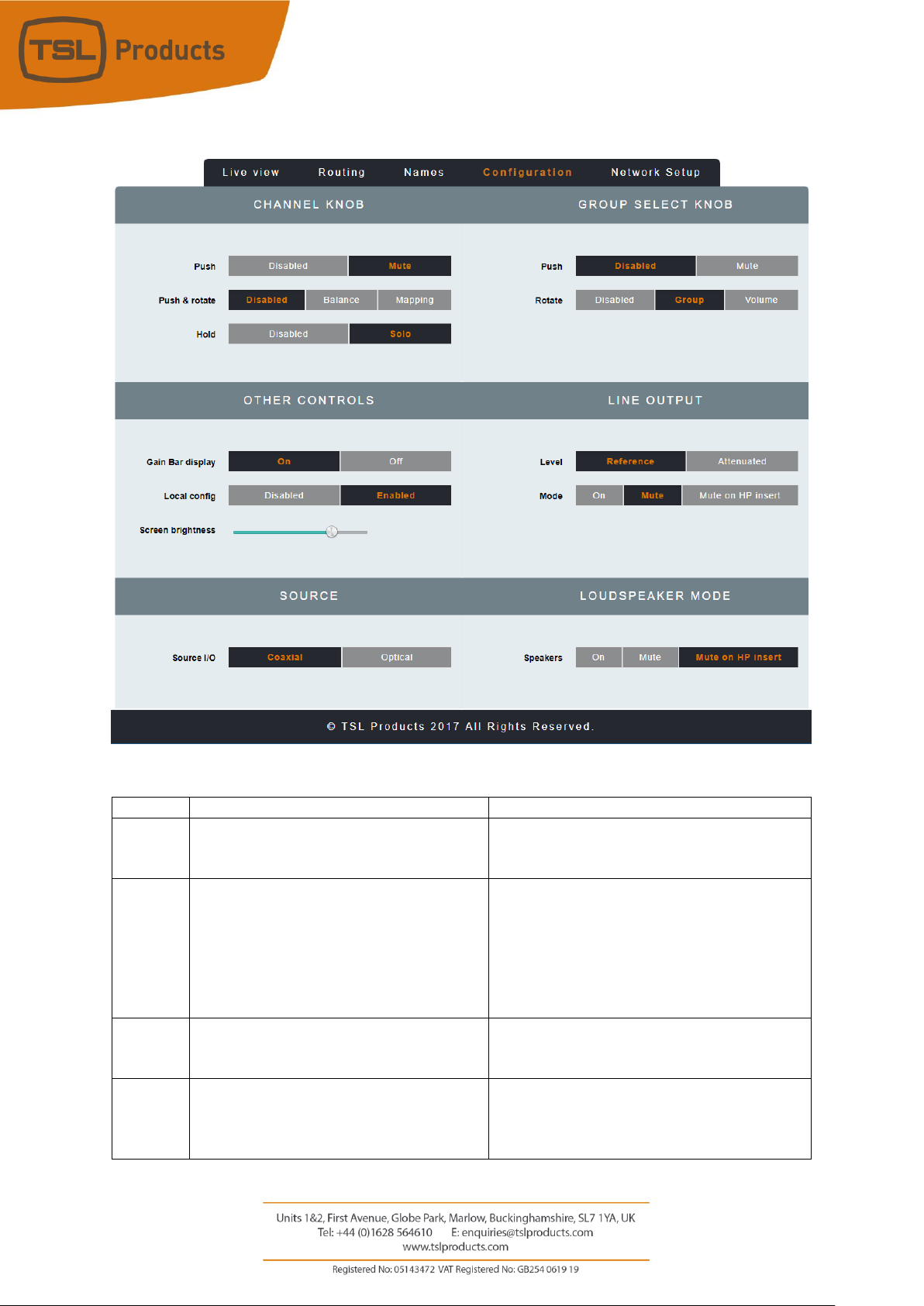
Clicking on the CONFIGURATION Tab of the MPA1-MIX-MADI Webpage displays the following:
Element
Function
Notes
1
Channel Knob Push
Enables/Disables ‘Push to Mute’ function of
Channel Rotary Encoders on front panel of
MPA1-MIX-MADI
2
Channel Knob Push and Rotate
Determines ‘Push and Rotate’ behaviour of
Channel Rotary Encoders on the front panel of
the MPA1-MIX-MADI. When set to Balance,
the Audio Balance of the selected Audio
Channel can be adjusted. When set to
Mapping, the Physical Audio Channel assigned
to the Mix Channel can be selected.
3
Channel Knob Push and Hold
Enables/Disables ‘Push and Hold to Solo’
function of Channel Rotary Encoders on front
panel of MPA1-MIX-MADI
4
Group Select Knob Push
Enables/Disables Push to MUTE function of
Headphone, Internal Loudspeakers and
Balanced Line Outputs using Group Select
Knob
1 2 3 45
6 7 8 9 10
11
12
Page 44

Page 44 of 72
5
Group Select Knob Rotate
Determines whether Group Select Knob is
Enabled/Disabled. Selecting Group allows Mix
Groups to be selected from the front panel of
the MPA-MIX-MADI, whilst selecting Volume
allows level adjustment on the Internal
Loudspeakers and Balanced Line Level
Outputs.
6
Gain Bar Display
Enables/Disables the Gain Bar Display from the
front panel of the MPA1-MIX-MADI
7
Local Config
Enables/Disables configuration from the front
panel of the MPA1-MIX-SDI
8
Line Output Level
Sets the Output Level of the Balanced Line
Level Outputs on the MPA1-MIX-SDI
9
Line Output Mode
Determines behaviour of Balanced Line Level
Outputs upon insertion of Headphones.
10
Screen Brightness
Sets the Brightness Level of the front panel
display
11
MADI Source
Determines if MADI Sources are derived from
Coaxial BNC or Optical SFP Input.
12
Loudspeaker Mode
Determines the behaviour of Internal
Loudspeakers upon insertion of Headphones
Page 45

Page 45 of 72
Clicking on the NETWORK SETUP Tab of the MPA1-MIX-MADI Webpage displays the following:
Element
Function
Notes
1
DHCP
Enables/Disables DHCP Mode
2
IP Address
Displays current IP Address and allows new IP
Address to be entered.
3
Subnet Mask
Displays current Subnet Mask and allows new
Subnet Mask to be entered.
4
Gateway Address
Displays current Gateway Address and allows
new Gateway Address to be entered.
5
Apply IP Address
Button to apply IP, Subnet and Gateway
addresses to the MPA1-MIX-MADI
Page 46

Page 46 of 72
MPA1-MIX-DANTE Web Page
Clicking on the LIVE VIEW Tab of the MPA1-MIX-DANTE Webpage displays the following:
Element
Function
Notes
1
Switch to Mute Headphone Output
Red when Muted, Grey when Active
2
Headphone Output Level adjustment
Adjust as required
3
Switch to Mute the Loudspeaker Output
Red when Muted, Grey when Active
4
Loudspeaker Output Level adjustment
Adjust as required
5
Mix Bank Selection
Drop down list allowing recall of one of 16
Audio Mix Banks (A-P)
6
Source Name
Displays Source and Friendly Name*
7
Channel Mute
Mutes Selected Channel
8
Channel Solo
Places Selected Channel in Solo Mode (Click
and Hold)
9
Channel Volume
Adjusts channel Volume within overall Mix
10
Channel Pan
Adjusts channel Pan within overall Mix
11
Audio Level Meters
Audio Level Display
1 2 3 4 5 6 7 8 9
10
Page 47

Page 47 of 72
Clicking on the ROUTING Tab of the MPA1-MIX-DANTE Webpage displays the following:
…
Page 48

Page 48 of 72
Clicking on the NAMES Tab of the MPA1-MIX-DANTE Webpage displays the following:
…
…
…
1 2 3 4 5 6 7
Page 49

Page 49 of 72
Element
Function
Notes
1
Mix Bank Identifier
Identifies one of the 16 Mix Banks (A-P)
2
Active Switch
Determines which MIX Banks are available for
selection on the front panel of the MPA1-MIXSDI.
3
Video Switch
Determines which SDI Video Source is
displayed on the front panel, reclocked SDI
Output and HDMI Output for each MIX Bank
4
Mix Bank Name
Friendly Name of MIX Bank*
5
Physical Input Identifier
Physical Input and Channel Number
6
Auto Naming Function
Not Supported
7
Friendly Name
Allows friendly names to be applied to MADI
Channels (1-64) and Analogue Audio Channels
Page 50
Page 50 of 72
Clicking on the CONFIGURATION Tab of the MPA1-MIX-DANTE Webpage displays the following:
Element
Function
Notes
1
Channel Knob Push
Enables/Disables ‘Push to Mute’ function of
Channel Rotary Encoders on front panel of
MPA1-MIX-DANTE
2
Channel Knob Push and Rotate
Determines ‘Push and Rotate’ behaviour of
Channel Rotary Encoders on the front panel of
the MPA1-MIX-DANTe. When set to Balance,
the Audio Balance of the selected Audio
Channel can be adjusted. When set to
Mapping, the Physical Audio Channel assigned
to the Mix Channel can be selected.
3
Channel Knob Push and Hold
Enables/Disables ‘Push and Hold to Solo’
function of Channel Rotary Encoders on front
panel of MPA1-MIX-DANTE
4
Group Select Knob Push
Enables/Disables Push to MUTE function of
Headphone, Internal Loudspeakers and
Balanced Line Outputs using Group Select
Knob
Page 51

Page 51 of 72
5
Group Select Knob Rotate
Determines whether Group Select Knob is
Enabled/Disabled. Selecting Group allows Mix
Groups to be selected from the front panel of
the MPA-MIX-MADI, whilst selecting Volume
allows level adjustment on the Internal
Loudspeakers and Balanced Line Level
Outputs.
6
Gain Bar Display
Enables/Disables the Gain Bar Display from the
front panel of the MPA1-MIX-MADI
7
Local Config
Enables/Disables configuration from the front
panel of the MPA1-MIX-SDI
8
Line Output Level
Sets the Output Level of the Balanced Line
Level Outputs on the MPA1-MIX-SDI
9
Line Output Mode
Determines behaviour of Balanced Line Level
Outputs upon insertion of Headphones.
10
Screen Brightness
Sets the Brightness Level of the front panel
display
11
MADI Source
Determines if MADI Sources are derived from
Coaxial BNC or Optical SFP Input.
12
Loudspeaker Mode
Determines the behaviour of Internal
Loudspeakers upon insertion of Headphones
Page 52

Page 52 of 72
Clicking on the NETWORK SETUP Tab of the MPA1-MIX-DANTE Webpage displays the following:
Element
Function
Notes
1
DHCP
Enables/Disables DHCP Mode
2
IP Address
Displays current IP Address and allows new IP
Address to be entered.
3
Subnet Mask
Displays current Subnet Mask and allows new
Subnet Mask to be entered.
4
Gateway Address
Displays current Gateway Address and allows
new Gateway Address to be entered.
5
Apply IP Address
Button to apply IP, Subnet and Gateway
addresses to the MPA1-MIX-SDI
Page 53

Page 53 of 72
Operation
The MPA1 Range has been designed to provide quick and easy selection of any desired audio source in an
intuitive manner that requires little in the way of training.
One of the key benefits of the MPA1 is the ability to personalise or tailor its configuration and behaviour
to suit a specific workflow, application or environment If the behaviour or configuration of your MPA1 is
not as expected or required, please check the configuration and settings made in the webpage belonging
to your MPA1.
All these settings can be made via the webpage of your MPA1 (see appropriate chapter earlier in this
manual).
The following chapters present an operational overview of each MPA1 variant.
Page 54

Page 54 of 72
MPA1-SOLO-SDI Operation
The front panel of the MPA1-SOLO-SDI is equipped with four rotary controllers as follows:
Encoder
Function
Notes
1
Headphone Volume
Rotate to adjust Headphone level as required.
PUSH to MUTE/UNMUTE currently selected
audio source.
2
Output Volume
Rotate to adjust the Audio Level of the Internal
Loudspeakers and/or Balanced Analogue
Audio Outputs.
PUSH to MUTE/UNMUTE Internal
Loudspeakers and/or Balanced Analogue
Audio Outputs.
NOTE: The exact behaviour of this control can
be modified using the MPA1-SOLO-SDI
Webpage, see Settings 2,4 and 5 on Page 19 of
this manual for further information.
3
Select/Menu
Rotate to Scroll through SDI Embedded Audio
Channels and/or AES and Analogue Audio
Channels.
PUSH to switch between Stereo and Mono
Audio Monitoring.
NOTE: Audio Sources available for selection
are determined by the settings found in
section 1 of the MPA1-SOLO-SDI Webpage.
See Page 20 of this manual for further
information.
The Select Menu Encoder is also used to access
the Settings Menu of the MPA-SOLO-SDI.
Further information can be found in the Initial
Setup chapter found on Page 17 of this
manual.
4
Video
PUSH to Switch between Audio Meter Display
and Video Display.
1 2 3
4
Page 55

Page 55 of 72
MPA1-SOLO-MADI Operation
The front panel of the MPA1-SOLO-MADI is equipped with four rotary controllers as follows:
Encoder
Function
Notes
1
Headphone Volume
Rotate to adjust Headphone level as required.
PUSH to MUTE/UNMUTE currently selected
audio source.
2
Output Volume
Rotate to adjust the Audio Level of the Internal
Loudspeakers and/or Balanced Analogue
Audio Outputs.
PUSH to MUTE/UNMUTE Internal
Loudspeakers and/or Balanced Analogue
Audio Outputs.
NOTE: The exact behaviour of this control can
be modified using the MPA1-SOLO-MADI
Webpage, see Settings 2,4 and 6 on Page 25 of
this manual for further information.
3
Select/Menu
Rotate to Scroll through MADI Audio Channels
and/or Analogue Audio Channels.
PUSH to switch between Stereo and Mono
Audio Monitoring.
The Select Menu Encoder is also used to access
the Settings Menu of the MPA-SOLO-MADI.
Further information can be found in the Initial
Setup chapter found on Page 17 of this
manual.
4
Balance/Pan
Provides Balance Control of Stereo Audio
Sources and Pan Control of Mono Audio
Sources. Setting affects Headphone, Internal
Loudspeakers and Balanced Analogue Audio
Outputs.
1 2 3
4
Page 56

Page 56 of 72
MPA1-SOLO-DANTE Operation
The front panel of the MPA1-SOLO-DANTE is equipped with four rotary controllers as follows:
Encoder
Function
Notes
1
Headphone Volume
Rotate to adjust Headphone level as required.
PUSH to MUTE/UNMUTE currently selected
audio source.
2
Output Volume
Rotate to adjust the Audio Level of the Internal
Loudspeakers and/or Balanced Analogue
Audio Outputs.
PUSH to MUTE/UNMUTE Internal
Loudspeakers and/or Balanced Analogue
Audio Outputs.
NOTE: The exact behaviour of this control can
be modified using the MPA1-SOLO-DANTE
Webpage, see Settings 2,4 and 6 on Page 29 of
this manual for further information.
3
Select/Menu
Rotate to Scroll through DANTE and/or MADI
Audio Channels.
PUSH to switch between Stereo and Mono
Audio Monitoring.
The Select Menu Encoder is also used to access
the Settings Menu of the MPA-SOLO-DANTE.
Further information can be found in the Initial
Setup chapter found on Page 17 of this
manual.
4
Balance/Pan
Provides Balance Control of Stereo Audio
Sources and Pan Control of Mono Audio
Sources. Setting affects Headphone, Internal
Loudspeakers and Balanced Analogue Audio
Outputs.
1 2 3
4
Page 57
Page 57 of 72
MPA1-MIX-SDI Operation
The front panel of the MPA1-MIX-SDI is equipped with ten rotary controllers as follows:
Encoder
Function
Notes
1-8
Audio Level
Rotate to adjust relative contribution of Sources 1-8 to Stereo
Monitoring Mix.
NOTE: Sources available are determined by the currently selected
Mix Bank (A-P) and the contributing audio channels for each Mix
Bank as set in the Routing Tab of the MPA-MIX-SDI. See Page 32 of
this manual for further information.
PUSH to MUTE/UNMUTE contribution of Sources 1-8 to Stereo Mix.
NOTE: PUSH to MUTE/UNMUTE functionality can be disabled by
Setting 1 of the MPA-MIX-SDI Webpage, see Page 35 of the manual
for further information.
PUSH and ROTATE to adjust Balance of selected source or to map
alternate audio source to encoder.
NOTE: PUSH and ROTATE functionality is determined by Setting 2 on
the MPA-MIX-SDI Webpage, see Page 35 of the manual for further
information
PUSH and HOLD to enable SOLO Monitoring of selected source.
NOTE: PUSH and HOLD to enable SOLO Monitoring can be disabled
using Setting 3 of the MPA-MIX-SDI Webpage, see Page 35 of the
manual for further information.
9
Headphone Volume
Rotate to adjust Headphone level as required.
PUSH to MUTE/UNMUTE entire Stereo Monitoring Mix from the
Headphone Output.
10
Select/Menu
Rotate to Scroll through Mix Banks A-P or to adjust Level of Stereo
Monitoring Mix.
NOTE: The behaviour of the Select/Menu encoder is determined by
PUSH to MUTE/UNMUTE Internal Loudspeakers and Balanced
Analogue Audio Outputs.
9 2 1 3 4 5 6 8 7
10
Page 58

Page 58 of 72
The Select Menu Encoder is also used to access the Settings Menu
of the MPA-MIX-SDI. Further information can be found in the Initial
Setup chapter found on Page 17 of this manual.
Page 59

Page 59 of 72
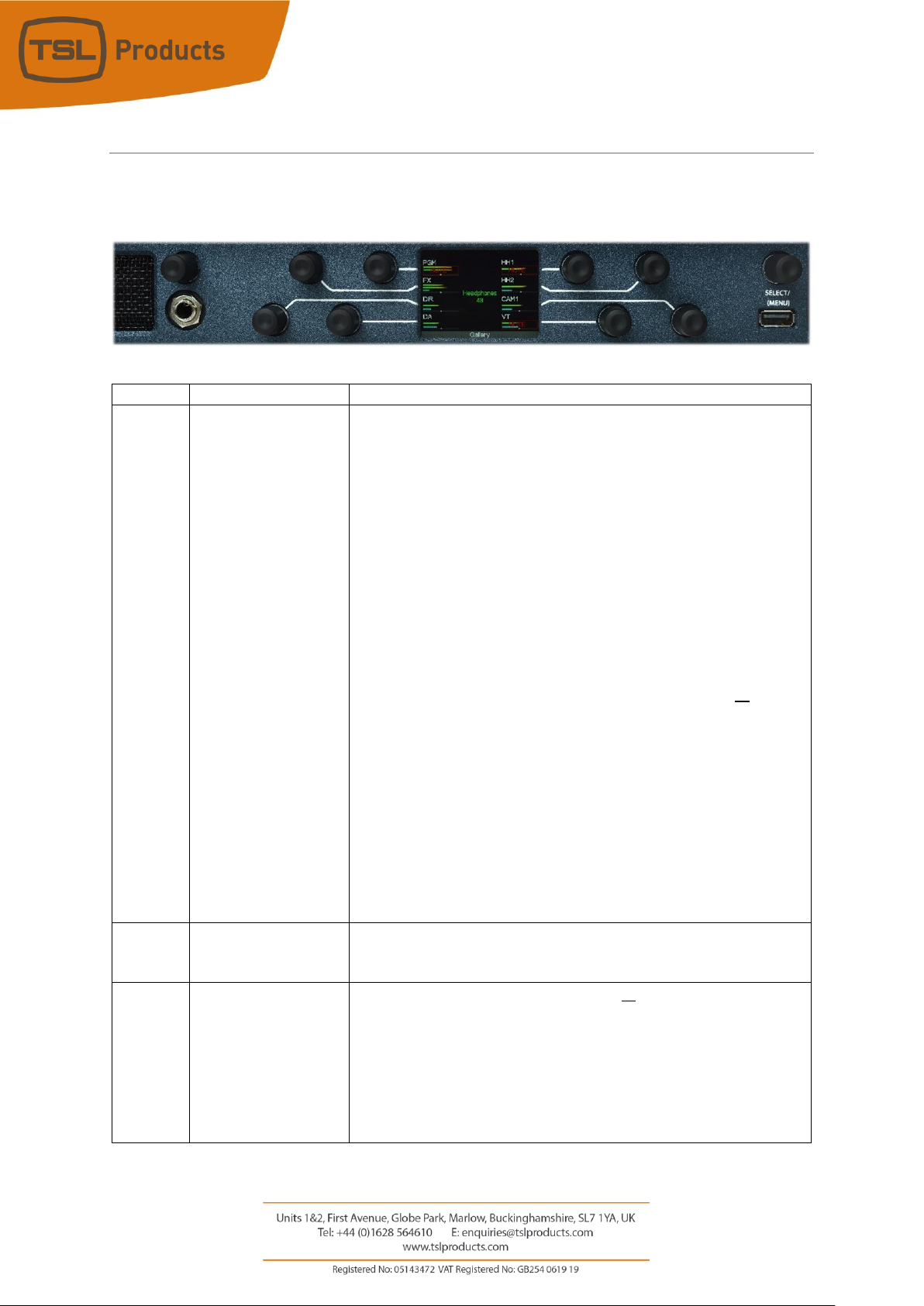
MPA1-MIX-MADI Operation
The front panel of the MPA1-MIX-MADI is equipped with ten rotary controllers as follows:
Encoder
Function
Notes
1-8
Audio Level
Rotate to adjust relative contribution of Sources 1-8 to Stereo
Monitoring Mix.
NOTE: Sources available are determined by the currently selected
Mix Bank (A-P) and the contributing audio channels for each Mix
Bank as set in the Routing Tab of the MPA-MIX-MADI. See Page 32
of this manual for further information.
PUSH to MUTE/UNMUTE contribution of Sources 1-8 to Stereo Mix.
NOTE: PUSH to MUTE/UNMUTE functionality can be disabled by
Setting 1 of the MPA-MIX-MADI Webpage, see Page 35 of the
manual for further information.
PUSH and ROTATE to adjust Balance of selected source or to map
alternate audio source to encoder.
NOTE: PUSH and ROTATE functionality is determined by Setting 2 on
the MPA-MIX-MADI Webpage, see Page 35 of the manual for further
information
PUSH and HOLD to enable SOLO Monitoring of selected source.
NOTE: PUSH and HOLD to enable SOLO Monitoring can be disabled
using Setting 3 of the MPA-MIX-MADI Webpage, see Page 35 of the
manual for further information.
9
Headphone Volume
Rotate to adjust Headphone level as required.
PUSH to MUTE/UNMUTE entire Stereo Monitoring Mix from the
Headphone Output.
10
Select/Menu
Rotate to Scroll through Mix Banks A-P or to adjust Level of Stereo
Monitoring Mix.
NOTE: The behaviour of the Select/Menu encoder is determined by
PUSH to MUTE/UNMUTE Internal Loudspeakers and Balanced
Analogue Audio Outputs.
9 2 1 3 4 5 6 8 7
10
Page 60

Page 60 of 72
The Select Menu Encoder is also used to access the Settings Menu
of the MPA-MIX-MADI. Further information can be found in the
Initial Setup chapter found on Page 17 of this manual.
Page 61

Page 61 of 72
MPA1-MIX-DANTE Operation
The front panel of the MPA1-MIX-DANTE is equipped with ten rotary controllers as follows:
Encoder
Function
Notes
1-8
Audio Level
Rotate to adjust relative contribution of Sources 1-8 to Stereo
Monitoring Mix.
NOTE: Sources available are determined by the currently selected
Mix Bank (A-P) and the contributing audio channels for each Mix
Bank as set in the Routing Tab of the MPA-MIX-SDI. See Page 32 of
this manual for further information.
PUSH to MUTE/UNMUTE contribution of Sources 1-8 to Stereo Mix.
NOTE: PUSH to MUTE/UNMUTE functionality can be disabled by
Setting 1 of the MPA-MIX-SDI Webpage, see Page 35 of the manual
for further information.
PUSH and ROTATE to adjust Balance of selected source or to map
alternate audio source to encoder.
NOTE: PUSH and ROTATE functionality is determined by Setting 2 on
the MPA-MIX-SDI Webpage, see Page 35 of the manual for further
information
PUSH and HOLD to enable SOLO Monitoring of selected source.
NOTE: PUSH and HOLD to enable SOLO Monitoring can be disabled
using Setting 3 of the MPA-MIX-SDI Webpage, see Page 35 of the
manual for further information.
9
Headphone Volume
Rotate to adjust Headphone level as required.
PUSH to MUTE/UNMUTE entire Stereo Monitoring Mix from the
Headphone Output.
10
Select/Menu
Rotate to Scroll through Mix Banks A-P or to adjust Level of Stereo
Monitoring Mix.
NOTE: The behaviour of the Select/Menu encoder is determined by
PUSH to MUTE/UNMUTE Internal Loudspeakers and Balanced
Analogue Audio Outputs.
9 2 1 3 4 5 6 8 7
10
Page 62

Page 62 of 72
The Select Menu Encoder is also used to access the Settings Menu
of the MPA-MIX-SDI. Further information can be found in the Initial
Setup chapter found on Page 17 of this manual.
Page 63
Page 63 of 72
MPA1-SOLO-SDI Front Panel Display
Page 64

Page 64 of 72
Display
Function
Notes
1
Channel Label
Label displaying Channel friendly name.
NOTE: Friendly names can be entered in the Channel Names section
displayed within the Names Tab of the MPA1-MIX-MADI Webpage.
See Page 40 of this manual for further information.
2
Audio Level Meters
Displays Audio Level of associated Source Channel
3
Gain Bar Display
Level of Channel contribution to Stereo Monitoring Mix.
NOTE: Inclusion of the Gain Bar Display is determined by setting 6 in
the Configuration Tab of the MPA-MIX-MADI Webpage. See Page 42
of this manual for further information.
4
Balance/Pan Display
The relative contribution to the Left and Right channels of the Stereo
Monitoring Mix is identified by the position of the Balance/Pan
5
Headphone and
Speakers Level
Displays
Display of current Headphone and Loudspeaker Output Level settings
(0 Min – 100 Max).
6
Mix Bank Name
Label displaying friendly name of currently selected Mix Bank.
NOTE: Friendly names can be entered in the Group Names section
displayed within the Names Tab of the MPA1-MIX-MADI Webpage.
See Page 40 of this manual for further information
Page 65

Page 65 of 72
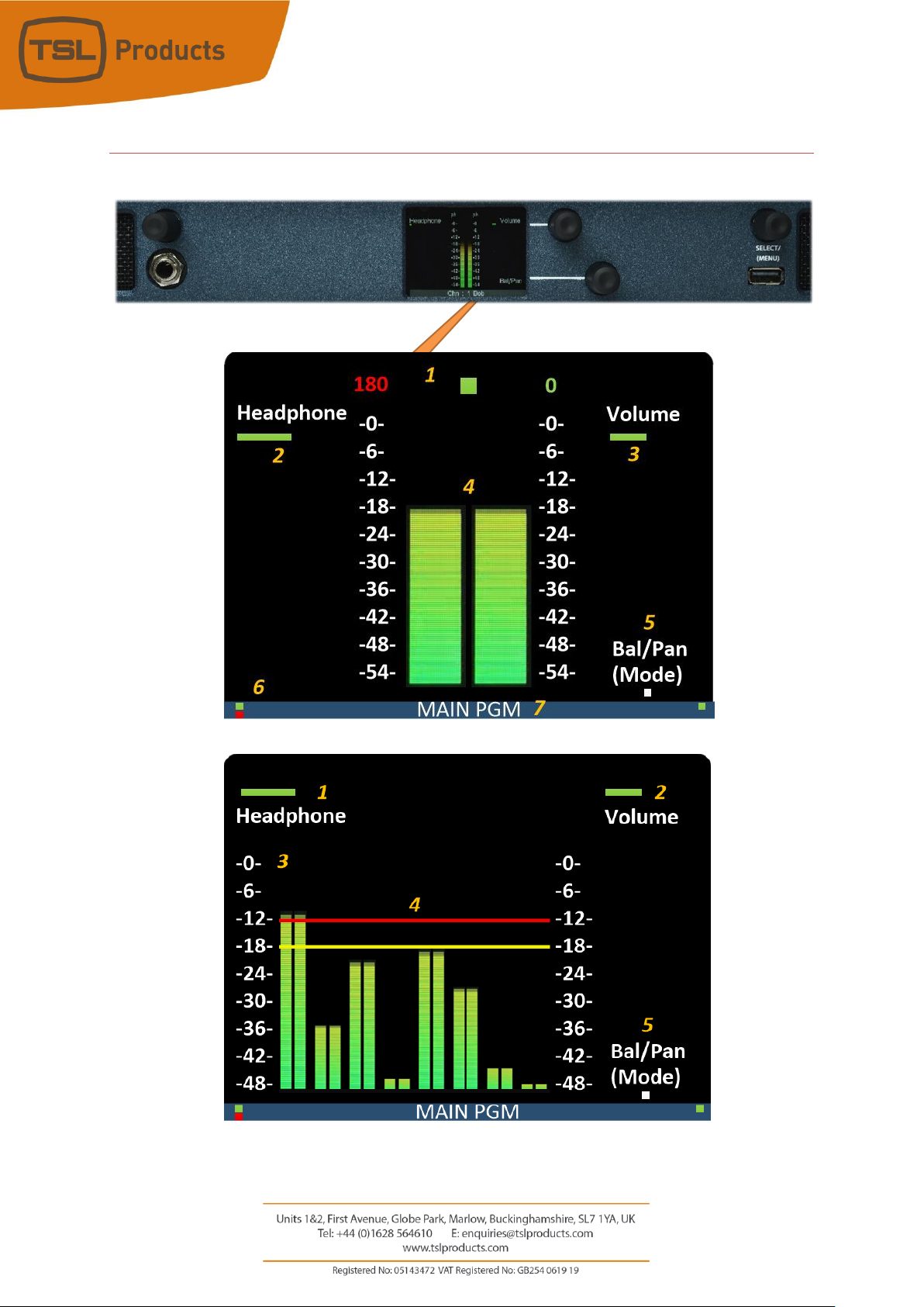
MPA1-MIX-SDI Front Panel Display
Display
Function
Notes
1
Channel Label
Label displaying Channel friendly name.
NOTE: Friendly names can be entered in the Channel Names section
displayed within the Names Tab of the MPA1-MIX-MADI Webpage.
See Page 40 of this manual for further information.
2
Audio Level Meters
Displays Audio Level of associated Source Channel
3
Gain Bar Display
Level of Channel contribution to Stereo Monitoring Mix.
NOTE: Inclusion of the Gain Bar Display is determined by setting 6 in
the Configuration Tab of the MPA-MIX-MADI Webpage. See Page 42
of this manual for further information.
4
Balance/Pan Display
The relative contribution to the Left and Right channels of the Stereo
Monitoring Mix is identified by the position of the Balance/Pan
5
Headphone and
Speakers Level
Displays
Display of current Headphone and Loudspeaker Output Level settings
(0 Min – 100 Max).
6
Mix Bank Name
Label displaying friendly name of currently selected Mix Bank.
NOTE: Friendly names can be entered in the Group Names section
displayed within the Names Tab of the MPA1-MIX-MADI Webpage.
See Page 40 of this manual for further information
Page 66

Page 66 of 72
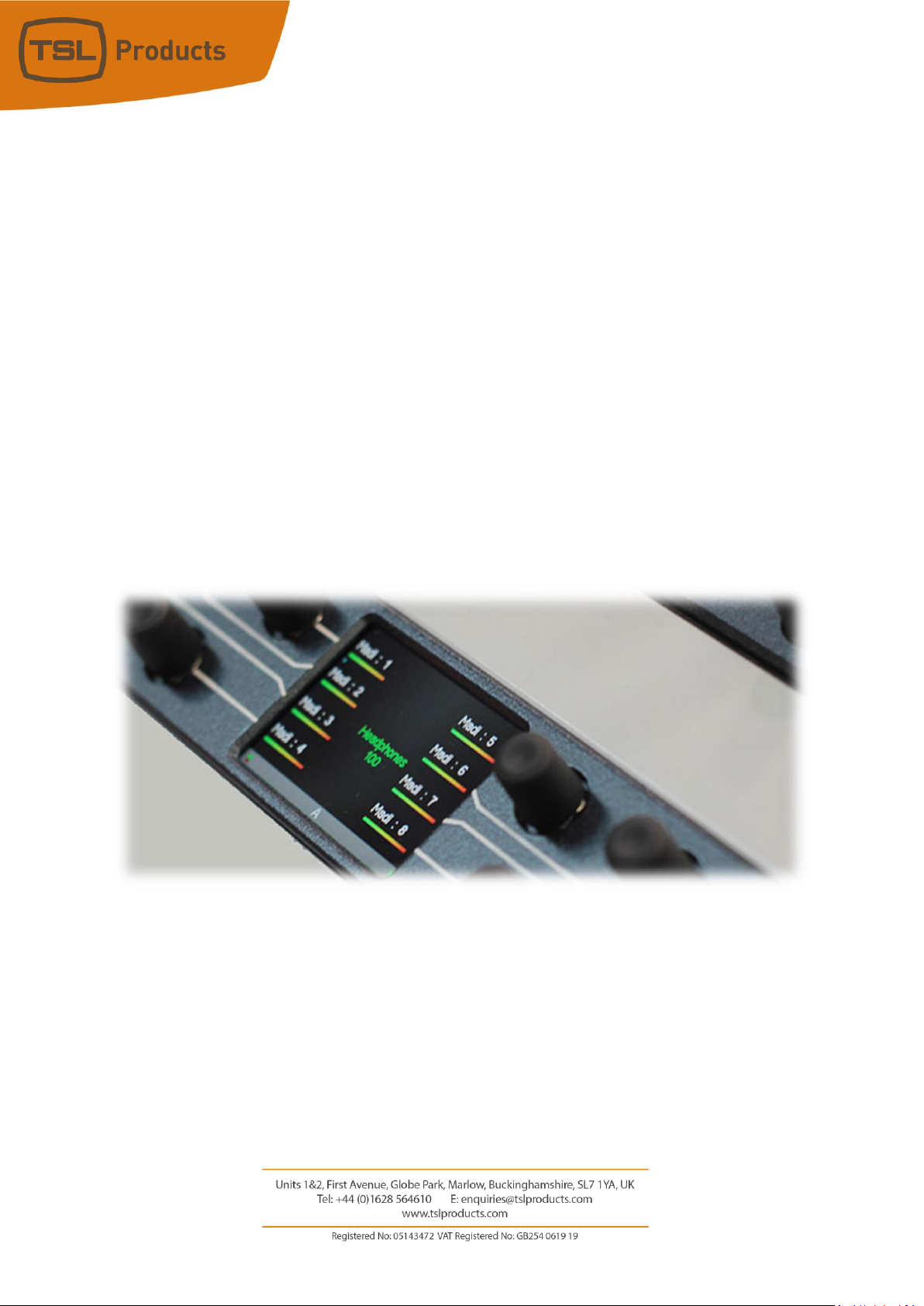
MPA1-SOLO-MADI Front Panel Display
Page 67

Page 67 of 72
Display
Function
Notes
1
Channel Label
Label displaying Channel friendly name.
NOTE: Friendly names can be entered in the Channel Names section
displayed within the Names Tab of the MPA1-MIX-MADI Webpage.
See Page 40 of this manual for further information.
2
Audio Level Meters
Displays Audio Level of associated Source Channel
3
Gain Bar Display
Level of Channel contribution to Stereo Monitoring Mix.
NOTE: Inclusion of the Gain Bar Display is determined by setting 6 in
the Configuration Tab of the MPA-MIX-MADI Webpage. See Page 42
of this manual for further information.
4
Balance/Pan Display
The relative contribution to the Left and Right channels of the Stereo
Monitoring Mix is identified by the position of the Balance/Pan
5
Headphone and
Speakers Level
Displays
Display of current Headphone and Loudspeaker Output Level settings
(0 Min – 100 Max).
6
Mix Bank Name
Label displaying friendly name of currently selected Mix Bank.
NOTE: Friendly names can be entered in the Group Names section
displayed within the Names Tab of the MPA1-MIX-MADI Webpage.
See Page 40 of this manual for further information
Page 68

Page 68 of 72
MPA1-MIX-MADI Front Panel Display
Display
Function
Notes
1
Channel Label
Label displaying Channel friendly name.
NOTE: Friendly names can be entered in the Channel Names section
displayed within the Names Tab of the MPA1-MIX-MADI Webpage.
See Page 40 of this manual for further information.
2
Audio Level Meters
Displays Audio Level of associated Source Channel
3
Gain Bar Display
Level of Channel contribution to Stereo Monitoring Mix.
NOTE: Inclusion of the Gain Bar Display is determined by setting 6 in
the Configuration Tab of the MPA-MIX-MADI Webpage. See Page 42
of this manual for further information.
4
Balance/Pan Display
The relative contribution to the Left and Right channels of the Stereo
Monitoring Mix is identified by the position of the Balance/Pan
5
Headphone and
Speakers Level
Displays
Display of current Headphone and Loudspeaker Output Level settings
(0 Min – 100 Max).
6
Mix Bank Name
Label displaying friendly name of currently selected Mix Bank.
NOTE: Friendly names can be entered in the Group Names section
displayed within the Names Tab of the MPA1-MIX-MADI Webpage.
See Page 40 of this manual for further information
Page 69

Page 69 of 72
MPA1-SOLO-DANTE Front Panel Display
Page 70

Page 70 of 72
Display
Function
Notes
1
Channel Label
Label displaying Channel friendly name.
NOTE: Friendly names can be entered in the Channel Names section
displayed within the Names Tab of the MPA1-MIX-MADI Webpage.
See Page 40 of this manual for further information.
2
Audio Level Meters
Displays Audio Level of associated Source Channel
3
Gain Bar Display
Level of Channel contribution to Stereo Monitoring Mix.
NOTE: Inclusion of the Gain Bar Display is determined by setting 6 in
the Configuration Tab of the MPA-MIX-MADI Webpage. See Page 42
of this manual for further information.
4
Balance/Pan Display
The relative contribution to the Left and Right channels of the Stereo
Monitoring Mix is identified by the position of the Balance/Pan
5
Headphone and
Speakers Level
Displays
Display of current Headphone and Loudspeaker Output Level settings
(0 Min – 100 Max).
6
Mix Bank Name
Label displaying friendly name of currently selected Mix Bank.
NOTE: Friendly names can be entered in the Group Names section
displayed within the Names Tab of the MPA1-MIX-MADI Webpage.
See Page 40 of this manual for further information
Page 71

Page 71 of 72
MPA1-MIX-DANTE Front Panel Display
Display
Function
Notes
1
Channel Label
Label displaying Channel friendly name.
NOTE: Friendly names for MADI and DANTE sources can be
entered in the Channel Names section displayed within the
Names Tab of the MPA1-MIX-DANTE Webpage. Friendly
names for DANTE sources can also be derived from the DANTE
Network when set to AUTO.
See the Channels Name section of the MPA1-MIX-DANTE
Webpage. See Page 47 of this manual for further information.
2
Audio Level Meters
Displays Audio Level of associated Source Channel
3
Gain Bar Display
Level of Channel contribution to Stereo Monitoring Mix.
NOTE: Inclusion of the Gain Bar Display is determined by
setting 6 in the Configuration Tab of the MPA-MIX-MADI
Webpage. See Page 45 of this manual for further information.
4
Balance/Pan Display
The relative contribution to the Left and Right channels of the
Stereo Monitoring Mix is identified by the position of the
Balance/Pan
5
Headphone and Speakers
Level Display
Display of current Headphone and Loudspeaker Output Level
settings (0 Min – 100 Max).
Page 72

Page 72 of 72
6
Mix Bank Name
Label displaying friendly name of currently selected Mix Bank.
NOTE: Friendly names can be entered in the Group Names
section displayed within the Names Tab of the MPA1-MIXMADI Webpage.
See Page 47 of this manual for further information
 Loading...