

Page 1

Version 01/12
Car Alarm System „A-136“
Page 2

2
Dear custom er,
In addition to th e user’s manual please note so me a dditional In formation:
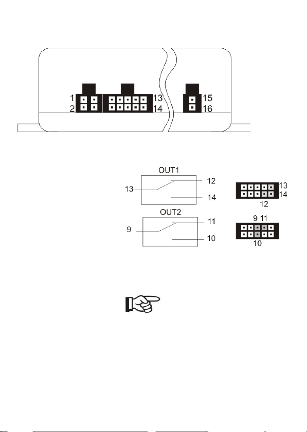
I. At the bottom of the product you see a wron g display of the pin assignment for
― Output2‖. The following Picture displays the correct assignment. Y ou can also find the right one i n
the user’s manual.
II. The Power cable of the c onnection jack 15/16 is equippe d wi th a miniature fuse. It’s
necessary to replace this fuse, if th e batt ery LE D remains d ark (in this case there is no ex ternal
voltage).
How to replace a fuse:
1. Unscrew th e circuit b reake r carefully.
2. Substitute t he mi niature fuse by a fuse o f the same type and nomin al current (5
3. Screw the circui t breaker together.
Thank you fo r your attention.
Your Mobi-Click team
x 20 mm, 250 V, 0, 63 A, slow -blow).
Page 3

3
Table of Contents
1. Intr oduc tion ................................................................................................................................. 5
2. Intended Use................................................................................................................................ 6
3. Scope of Delivery........................................................................................................................ 6
4. Explanation of Symb ols............................................................................................................. 7
5. Safety Infor mation ...................................................................................................................... 7
6. General No tes on Rech ar geable Batteries............................................................................. 8
7. Pr oduct Descr iption ................................................................................................................... 8
8. Conn ections and LEDs .............................................................................................................. 9
8.1. Casing Ove rview .............................................................................................................. 9
8.2. Description of the C onnectio ns....................................................................................12
8.3. Notes on the Installation ................................................................................................15
8.4. Notes on the Electrical Connection ..............................................................................16
9. Comm issionin g - First Steps ..................................................................................................17
9.1. Operating Voltage..........................................................................................................17
9.2. Changing the PIN Code to „1513―................................................................................18
9.3. SIM Card Insertion.........................................................................................................18
10. Gener al Desc ription s.........................................................................................................19
10.1. Product Status a nd Mode..............................................................................................19
10.2. Wireless R emot e Contr ol ..............................................................................................20
10.2.1. Product C ont rol wi th the Wireless Remote C ontrol............................................21
10.2.2. Wireless Remote Co ntrol Batt ery Change...........................................................22
10.2.3. Coupling of a Remote Cont rol to t he Device .......................................................22
11. Con figur ation via Text Message ......................................................................................22
11.1. Introduction to the Comma nd For mat ..........................................................................23
11.2. Special Co mma nds .......................................................................................................25
12. Function al Descr iption s....................................................................................................26
12.1. General C onfigu ration Commands ...............................................................................26
12.1.1. Setting Time and D ate (TIME, DATE )..................................................................26
12.1.2. Administratio n of Phone Book (TEL, TEL 1,…)....................................................27
12.1.3. Changing th e Device Name (Name) ....................................................................29
12.1.4. Changing th e PI N Code ( PIN) ...............................................................................29
12.1.5. Changing th e Calling So und and Volu me Settings (AUDIO) .............................30
12.2. In- and O utputs ..............................................................................................................31
12.2.1. Relay Out puts (O UT1, O UT2)...............................................................................31
12.2.2. Swi tching Inputs (IN1, IN2) ....................................................................................33
12.2.3. Operating Voltag e Monitoring (VOLT AGE) ..........................................................34
12.2.4. Vibration Ala rm (S CHOCK) ....................................................................................35
12.3. Additional F unctions ......................................................................................................35
Page 4

4
12.3.1. Time Limitation Alarm (HO LDA LARM) ................................................................ 35
12.3.2. Wireless Re mote Con trol a nd its Function (RFBUTTON) .................................. 37
12.3.3. Reaction at C all (INCALL) ..................................................................................... 38
12.4. Position Determination .................................................................................................. 40
12.4.1. GSM Cell Loca tion (CELL) .................................................................................... 40
12.4.2. General GPS Localisation (GPS ) ......................................................................... 41
12.4.3. Submission of a Web Link with GPS P osition (GPSMAP) ................................ 42
12.4.4. Automatic Submissi on (GPS, GPSM AP, Special Function) ............................... 43
12.4.5. Energy Savi ngs Mode (GPSSAVE ) ...................................................................... 44
12.4.6. Programming the „ GPSZONE―.............................................................................. 44
12. 5. Sys tem F unc tions ....................................................................................................... 48
12.5.1 . T ime betw een Tw o Ala rm Messa ges (ID LEALA RM) ............................... 48
12.5.2 . Voltage Hys tere sis (HYSVO LT) ................................................................... 49
12.5 .3. Rese tting t o Ba sic Setti ng (RES ET SET UP) .......................................... 50
13. Restor ing Default Settings......................................................................................................... 50
14. Maintenance................................................................................................................................ 51
15. Dispo sal ...................................................................................................................................... 51
16. Declaration of Conformity (DOC) ............................................................................................... 52
17. T echnical Data ............................................................................................................................. 52
Page 5
5
1. Introduction
Dear Customer,
Thank you for pu rch asing this product.
This product co mplies w ith the st atutory national and Eu ropean req uirements . To m aintain this
status and to ensu re safe ope rati on, you as the user must obse rve these ope rating inst ructi ons!
Read th e c om plete oper ating instru ctions befor e takin g the pr od uct into
oper ation; ob ser ve all op er ating n otes and safety in for mation.
All company names and p roduct n ames are t radem arks of th eir respec tive owners. All rig hts
reserve d.
These op eratin g instr uctio ns desc ribe th e function and operation at th e time of print
(see d ate on the top right of the titl e page).
Chang es that se rve p roduct im provem ent can be perfor me d at any tim e. The most current
opera ting inst ructions are offe red on ou r websites in the download are a for the resp ectiv e
product on our websit es in a tim ely mann er.
If ther e ar e any tec hnic al questions, con tact:
support@tslelektronik.com.pl
Please note:
Page 6

6
2. Intended Use
The product serves to monitor an obj ect. For this, s ensors like vibratio n, switchi ng in puts (up
to 32 V/ DC) and th e GPS signal are availa ble. The product must only b e install ed in the drive r
space, splash-wate r p rot ection i s requi red.
Two switching relays for 30 V/DC, 2 A can b e switch ed remo te-controll edly by co nsume rs o r
automa tically. Swi tching th e consume r must not influ ence the safe ty and operational readi ness
of the v ehicl e .
An ex ternal microphone and a speak er permit ph one call s. I nte rio r monitoring must be
according to the stat uto ry p rovisions .
Any other use tha n describ ed before is not i nte nded and may caus e loss of wa rranty/
guara ntee.
The custome r is responsibl e for applicatio n of the prod uct in acc orda nce with the law. Co nrad
Electr onic d oes not ass u me any res po nsibi lity/liabilit y ex ceeding applicatio n of the product as
descri bed here.
No pa rt of this product must be modified or converted.
Read these ope rati ng i nstructio ns t horoughly and c arefully, they con tain a lot of i m portant
info rmation for asse mbly, com missioni ng and operati on. Observe all safety info rm ation in
these opera ting instructi ons!
3. Scope of Delivery
• Car ala rm syste m
• Remote Con trol
• Microph one
• Speak ers
• Light diode
• Mains cable
• Various conn ection w ires
• Operating inst ructio ns
Page 7

7
4. Explanation of Symbols
An ex clamation ma rk in a t ria ngle indicat es im portant not es in thes e o perating
instructions that must b e strictly obse rve d.
The „hand― symb ol indicates speci al info rm ation and advic e o n opera tion.
5. Safety Information
The guar antee/w ar ranty will expir e if dam age is incurr ed resu lting from noncomplianc e with the oper ating instr uctions! We do not assume any li abili ty
fo r consequential damage !
We do not a ssume any liabili ty fo r damage to p rop erty or per sonal injur y caused by
impr op er use or the failure to o bser ve th e sa fety ins truc tions! In suc h cases th e
guar antee/w ar ranty will expir e!
• For s afety and li ce nsing reaso ns ( CE ), unaut horis ed co nversi on an d/or
modific ation of the sys t em is no t pe rmitt ed.
• The system only serves to trig ge r ala rms but d oes not reliev e the user from his
diligence oblig ation.
• Setting when the relay sw itches and what effects this has is subject to the area
of respo nsibility of the cust omer. The man ufactu re r does not as su me any liabili ty
for da ma ge th at occ urs in this cas e.
• The GPS functi o ns only serv e to monit or p roperty. Th e custome r is person ally
responsible for complianc e with the statutory require ments fo r f urth er m onito rin g.
• Du ring inst allation and oper atio n, obse rve the applicable approval provisions
and th e ro ad traffic ordi nance (Straßenv erkehrso rd nung).
• Ensu re p rope r co mmissio ning of the system. Obs erv e the ope rati ng instructions
for it.
• Avoi d st rong mec hanic al strain on the syste m comp onents.
• Do not ex pose the devic e to any high te mperatu res , dripping or spl ashing water,
strong vibratio ns or heavy mecha nical stress .
• Consult an ex pert wh en in do ubt as t o the oper atio n, the safe ty or the con necti on of the
system.
Page 8

8
• Do no t leave the p ackaging m aterial lying aroun d carelessl y si nce such mate rials ca n
become dange rous toys in the hands of chil dren.
• Keep the device out of reach of c hildren. It is no t a toy .
• Also obse rve the a dditio nal safety inf ormation in the individual cha pters of thes e
instructions .
• If you are not su re about the correct con necti on or if questi ons arise whic h are not covere d
by the op erating inst ructi ons, please do not hesitate t o co ntact us or ano ther speciali st.
6. General Notes on Rechargeable Batteries
• Keep the rech argeabl e battery out of reach of c hild ren.
• Leaking or d amaged b atteries /rechar gea ble batt eries can cause chemic al burns to skin
when t ouc hed witho ut the us e of ade quate p rotective glov es.
• The recha rgeabl e batte ry must nev er b e sho rt-ci rcuite d or thrown in to fire. Th ere is a risk of
fire and ex plosion!
• Never open or disass emble the rech a rgeable batt ery!
• If the recharg ea ble bat tery heats up strongly when char ging, in terrupt the chargi ng process!
• Never c harge the battery un observe d.
• For reas ons of s afety, only c harge th e rec ha rgeable batt ery on a heat -resista nt surface .
• If the recha rge able batt ery shows any defo rmatio n, holes or oth er obvious defects, no long er
use the recha rg ea ble b attery and do not try t o ch arge it.
• Dispose of the r echa rgeable batte ry envi ronmentally co mpatibly.
7. Product Description
The car al arm syste m can be us ed to m onit or a vehicle. The prima ry task is not i n frigh teni ng
the thief away via the sp eake r but via live tr ans mission of an ala rm mess age to up to 6 pho ne
numbe rs by tex t message.
If the senso rs and exte rnal electr onic s (co nnec ted to the swi tching i npu ts) recog nise any
Page 9

9
impermissibl e i nteraction, v arious ac tions like al arm via tex t message and calli ng or swi tchi ng
consu me rs may be triggered .
The custome r may at any time perf orm ot her actio ns by sending tex t messa ge from hi s mobile
phone, e.g. dete rmin e the cu rrent GPS position (coo rdin ation o r web link ), re quest the status,
switch the relay, c heck the switc hing i nputs o r pe rfo rm a „ sil ent call― to hear w hat is cu rrently
taking place inside the vehicle.
The mic ropho ne or s peake r can be use d t o acc ept c alls an d cal l p re-set phone numbe rs.
Many transv erse fu nctions (switc hing rel ays when deactiv ati ng the ala rm, the call c auses an
answeri ng tex t message with the cu rrent GPS position, etc) can be us ed by the custo mer to
config ure the product as desi red.
The GPS receive r is us ed to det ermine an d monit or GP S zon es (A rea, GeoFenc e), i.e. places
where the produc t may be p rese nt.
The USB -int erface, which is not mandato ry for operatio n o r c onfigu ratio n can b e used by the
custom er for fir mwa re updat es to rec eive furth er functions.
The product is s ecured against mani pulati on with an i nternal b attery.
8. Connections and LEDs
The product is ex plained s tep by step i n the fol low ing c hapte rs.
To ensu re tha t th e devic e is set up correctly, make s ure to read t hese oper atin g
instructions, includi ng the sa fety i nstructio ns, completely and attentively b efore use .
Assembly and elec trical connecti on of the syst em must be perfo rmed by a specialist.
8.1. Casing Overview
1. GSM status LED
2. Battery status LED
3. GPS st atus LED
4. RF st atus LE D (rem ote co ntrol)
5. Ex pa nsion p ort
6. Mi ni-USB
7. Ex ternal alarm LED and switchi ng plus input
Page 10

10
8. Switc hing inp uts an d rel ay conn ections
9. Microphon e/ spe aker connec tion
10. Microphon e/ spe aker connec tion
11. Ex ternal power supply
12. Prog rammin g switch (RF )
13. O pe ning GPS cable
14. SIM c a rd hold er
15. RESET
Page 11
11
In the follow ing , the PI N assi gnmen ts are d escrib ed.
All rel ays are in the co nditio n „ OFF/RESET― .
1. LE D + ex ternal ala rm LE D
2. LE D – ex ternal alarm LE D
3. P+ swi tching plus
4. No t assigned
5. IN1 switching input a
6. IN1 switc hing input b
7. IN2 switching input a
8. IN2 switching input b
9. O UT2 relay out put co mm on
10. O UT2 relay out put closer
11. O UT2 relay out put opene r
12. O UT1 relay out put opene r
13. O UT1 relay out put co mm on
14. O UT1 relay out put closer
15. VCC volta ge sup ply pl us/+
16. GND volt age su pply min us/ -
Page 12

12
8.2. Description of the Connections
GS M status LE D (1):
This LED shows the c urrent GSM st atus. For this, the LED has the f ollowing presen tati on
opti ons:
• LED is lit green: Searching fo r GSM ne twork
• LED fl ashes green (ev ery 1 s): Device registered in the netw o rk
• LED fl ashes green (ev ery 1/ 2 s): C all / ph one con necti on
• LED fl ashes red: No netw ork co nnection / PIN error / inv alid SIM ca rd / PUK / …
• LED off: No powe r supply pres ent / d evic e d efec tive i f volt age supply an d SIM ca rd are
prese nt
Batter y status LED (2) :
The internal bat tery is charged and managed via a se parate h ardwa re. Th us, the ba ttery c an
also be cha rged when no SIM c a rd is inserted and the entire GS M hardware is deactivated.
It i s unimpo rtant of wh ether the bat te ry is charged via the ex ternal voltage supply (on -b oard
voltag e) or via USB.
This LED provides the following infor mation:
• LED is lit red: The b attery is being c harged
• LED is lit green: The ba ttery is c harg ed
• LED is lit re d and green: An error was reco gnised (e.g. no batte ry present)
• LED o ff: No ex ternal voltage s u pply present
GPS sta tus LED ( 3):
This LED is used to recog nise the activity and st atus of the ex ternal GPS r eceiver.
The follow ing dis play options are av ailable for this :
• LED fl ashes blu e: Current GPS position dete rmined
• LED is lit blu e: GPS positi on not determined / det ermina ble
• LED o ff: GPS module is in sle eper m ode / sw itch ed off / not present
RF status LED (4):
This LED s hows whethe r the RF recipient of th e wireless remo te cont rol has receive d a signal
from a vali d rem ote con trol.
Page 13

13
Obse rve that only correctly coupled remo te co ntrols are recognis ed and dis playe d. How to
couple a rem ote con trol can b e taken from the co rrespondi ng c hapter.
The LED has the following display informatio n acc o rdingly:
• LED fl ashes red: Sig nal r eceived by valid rem ote co nt rol
• LED o ff: Wai ting fo r sig nal
RF bu tton:
You can reach the RF butto n wi th a pointe d object throu gh the corres ponding openi ng. This
is requi red t o couple a new / different wireless remot e cont rol wi th the produc t. For more on
this, see the co rrespon ding chapte r.
Reset bu tton :
The devic e can b e res et to fac to ry settings with a pointe d objec t. For more on this, see the
corresp onding chap te r.
Feedthr oug h GP S rec eiver :
The GPS rec eiver is delive red pre-asse mble d. The GPS receiv e r must be place d so that a sig ht
connection to the sky is p resent w ith as few obs tacles as possibl e. Partic ularly obse rve panes
that are applied w ith film or vapo rise d because th ey interf ere with o r even block the GPS sign al.
The same ap plies for fro nt or rea r win dow heati ngs.
Exter nal p ower sup ply:
Use pins 15 and 16 to supply the devic e with the vehicle’s ba ttery vol tage (permanent plus ).
The voltage range is between 6 and 3 2 V/ DC and thus match es nea rly any im portant v ehicle
volta ge.
The current lo ad may be up to 700 mA (peak ) at bad GSM rec eption, active sw itchi ng relays
and active GPS.
Two connec tion s fo r speaker / microp hone:
Eithe r the inclu ded micr oph one or the speake r can be conn ected to the two RJ12 sock ets. Both
sockets are assign ed in precisely the sam e ma nner an d switc h ed i n parallel.
The PI N assign ment co rresp onds to th at of a sta ndard phone handse t. Func tion
cannot be gu aranteed for ev ery ph on e han dset .
Exter nal LED c on nec tion :
Pins 1 and 2 are intend ed for connection of the ex ternal LED. Please use recommend ed
accessories only (see w ww.con ra d.co m)
Page 14
14
P+ switching plu s recognition:
Connect a sw itching plus signal to pin 3 and 4 . Functio nally, howev er, this input only serves
to directl y trigger an ala rm because the switching plus refers to an imp ermissi ble ac tion in the
„ ALARM ENABLE― mode.
The refer ence po te ntial is GND from the ex te rnal powe r s upply (16 ). No volta ge above 3 2 V
must be pres ent he re.
To avoid unint ended short circ uit for wi ring, only the „P+― pin (3) is assigne d. The
other pin was not c onnect ed. The refore, if no reaction appears w hen the swi tc hing
plus is activ at ed, this pin may have been c onnected.
Switch ing inp uts IN1 / IN2:
The pins 5 and 6 fo r „ IN1― , as well as 7 and 8 for „ IN2― serve to recognise vario us switching
conditio ns in the v e hicl e. Th ese lines can be directly co nnected , e.g. to lamps, door cont acts
or other sw itchable cons umers. An integ rated rectifie r and o ptoc ou pler p rotects the d evice
from pola rity reve rsal and sho rt circ uit.
It must only be e nsured that a volta ge difference of at least 4 V and no more than 32 V is pendi ng
betwee n the two pins (no ma tte r the pol arity) and the resp ective sw itching in put is recognis ed
as „HIGH― . A v oltage of less than 2. 5 V is securely interpre ted as „LOW― . The area b etween
serves to prevent multi ple ala rming and can only be assigned to a level und er specific
circums tances. For more o n this, see the c orres ponding chapt er.
Relay switch ing outputs O UT1 / OUT2:
The devic e has two relays with alte rnate cont ract that are int ended fo r a voltage o f 30 V an d
a cu rrent of 2 A.
When a high er p ower is to be sw itched, the c orresp ondi ng r elays mus t be
connected ex ternally.
The relays are not bist able and acco rdingly return to „ OFF― or „ RESET― when al l voltage
supplies (bat te ry, USB , ex ternal volta ge) dr op or a system reset is performed.
Obse rve th at the devi ce for the relays has no extra f use inst alled. Th erefore,
provide an ex ternal fuse if requi red (depe ndin g on appl ication cas e).
Impro pe r wirin g and switching of imp ermis sibl e cons umers (buzzer, igniti on plus )
may c ause a risk of sh o rt ci rcuit, fire and loss of the gene ral operating per mit.
Expansio n p ort:
This port was in tende d fo r poss i ble ex pansio ns. T his i s possi bly avail able on our
websi te: ww w.mobi-click.c om.de .
Page 15

15
USB c on nec tion :
You may us e this USB connectio n to updat e the pr oduc t firmwar e to th e latest v ersion. For this,
the co rrespo nding update prog rammes may b e provide d on the product side a t www .conrad.com.
The softw are version cu rrently inst alled on the prod uct can be taken f rom every answer t ext
mess age .
Ideas an d wi shes fo r new functio ns o f the prod uct can be put on th e forum page. Where
technic ally an d econ omical ly possi ble, we w ill alw ays try to sensi bly put this i nto p ractic e.
8.3. Notes on the Installation
• It can be installed i n any positio n.
• Observe t hat th e re is enough space for cables when c hoosi ng the instal latio n positio n.
Strongly bent cables ( particul arly ri ght behi nd the plug ) inc reas e th e risk of ca ble breaks and
may ca use contact proble ms in the pl ug. The PCB is unde r a st rong mechanical s train due
to this.
• To warrant the d evice functi on, cho ose a mo unti ng site where the GMS n etwork rec eption
is as g ood as possi ble.
• The applica tion sit e sho uld be protecte d against overheatin g of the devic e, ex cessive
moistu re and dus t.
• The product s hould be take n to a s ite where vehicle vibratio n can be measu red.
• The product must not be s ubject to c ontinuo us strong vibrations (vib rati ng machi nes, direct
motor /chassi s contact, etc .).
• The produc t is not p rotect ed against weathe r and there fore must be installe d insid e the
vehicl e .
• Observe th at the SIM ca rd h older position was placed close t o the casing hol der on pu rpos e.
You may use a co rrespondi ng screw to secu re the SI M ca rd against im permissibl e remov al.
Replacin g the batter y:
If the batte ry must be repl aced, o bserve the f ollowing i nstructio ns:
1. All removal cable c o nnectio ns mus t be removed from the device ; separat e it from the
power su pply unde r all circums tances
2. Re move th e SIM ca rd.
3. Loos en the 4 scr ews on th e p roduct bott om; tu rn it out.
Page 16

16
4. Now the casing may be used ca refully ; do not apply any fo rce!
Obse rve the GPS recei ver! It may b e necessa ry to lo osen the screws a t the G PS
cables for relief .
5. The bat tery is connected to the m ain PCB via a pl ug s ecu red agai nst pol arity reversal;
carefull y discon nect the bat te ry.
Any cha nges in the vehicle that beco me n ecessary fo r the inst allatio n of the alarm
system or oth er c ompon ents must be carried out in such a way th at n either traffic
security nor the c onst ructi onal an d func tional sta bility of the car are affect ed.
The operation permit may lapse eve n wh en saw ing out the sh eet part.
No parts must be inst alled in the airba g trigger area becaus e this may caus e injury to the
vehicl e passe ngers i n case of accide nt.
Never loosen the plugs for an airbag, which may cause unint ended t rigge ri ng of the airbag o r
functio nal impairme nt.
If there are any doubts re gardin g selecti on of the installatio n site, i nq uir e for informa tion from
your ca r v endor.
Before drilling the bores, m ake sure t hat no elec tric c ables, b rak e lines , the fuel ta nk or simil ar
are d amaged.
When using tools to i nstall yo ur ala rm system, obs erve the t ool m anufacturer’s safety
info rmation .
When i nstalling the p roduct, take into co nside ra tion the risk of acci dent which can arise from
devices being torn away in the case of an accident. T he ref ore, you sho uld sec ure eve ry
component in a place where it cannot be danger ous to passe ngers.
In dou bt, installa tion m ust be pe rfor med by a s pecialist .
8.4. Notes on the Electrical Connection
• The max imum load resilienc e in the relays mus t not b e exceed ed. If re quired , they m ust b e
protect ed f rom ov erload with addition al exte rnal fuses.
• The external c ables must be ke pt as short as possible and remainin g line len gths must n ot
be c oiled .
• Too-str ong te mpera ture fluctuatio ns may l ead to t empora ry im pairment and requi re manual
reset in ex treme cases .
Page 17

17
• The produc t is not i ntended for th e „ Safety― area an d the ref ore does not co rrespon d to any
SIL/ASIL l evel.
The elect rical c onnection must be made by a s peci alist.
To avoid short ci rcui ts and resulti ng damage to the devi c e, the negative pol e (GND/
earth ) must b e discon nect ed during c onnectio n.
Only connect th e negative pole of the vehicle battery wh en you have compl etely
connected the devic e and ch ecked th e con nections.
Obse rve th e no tes of the ve hicle manufacturer so t hat the st ored data of the v ehicle
are not lost (e.g. radio c ode).
You sho uld only use a volt meter or a diode test lamp for checki ng the voltag e on
the on-board cables as normal test lamps consume ex cessive currents and can
thus damage the elect ronic system of the ca r.
When l aying the cables , make su re that th ey are not squeez ed or scoured on s harp
edges. Use rubber gromm ets for the feed-th ou gh poin ts.
When placing the senso r lines in the trunk, us e rubb er sle eves or so mething simila r
to avoid i mpairin g tight ness of the ve hicl e in terior.
When placing the lines in d oor pillars, etc., ensu re that you do not imp air any safetyrelevant devices (e.g. side airbags). The lines m ust not be pl aced in the ai rbag
trigge r area.
9. Commissioning - First Steps
Prior to com missionin g th e p rod uct, c heck whethe r it is suited for the intended ap plicatio n!
In case of d oubt, alway s co ntact a sp ecialist, ex pert or the manufact urer of the produc ts use d!
The follow ing is n eeded for op eration and configu ration of th e devi ce :
• A comm on m obile phone wi th SIM ca rd for confi guratio n of the device.
• An ad ditional SIM c ard (prepaid or c ont rac t) fo r the device.
• A vol tage so urce ( USB port or di rec t volt age so urc e)
9.1. Operating Voltage
The product may be su pplie d with power via USB as well fo r testing. The battery LED show s
whethe r the o perating v olta ge was connected co rrectly, no matter the device s tat us:
• LED off = no ex ternal volta ge sup ply
Page 18

18
• LED green/red = ex ternal v oltage supply pres ent
9.2. Changing the PIN Code to „1513“
Every SIM card has a PIN code. Bec ause th e car al arm sy st em uses its ow n PIN processin g,
the SIM card PIN code must be cha nged to that of th e produc t.
The followin g steps are r equir ed for this:
1. The SIM ca rd in tended for th e car alarm syste m must be inse rted in a mo bile pho ne.
2. Ac c ording to the op erating i nst ruc tio ns of the mobile pho ne, the PIN code must be
changed to 151 3.
3. The SIM ca rd wi th th e ch an ged PI N c ode mus t be remov ed from the m obile phone .
4. The SI M card w ith the cha nge d PI N code can now be inse rted in th e inte nded device slot.
The SIM c ard slot fo r this is on the short device sid e.
9.3. SIM Card Insertion
The SIM ca rd wi th the PIN num ber „ 1513― must be inse rt ed in the d evice as sh own in th e
figu re on th e righ t.
After ins ertion of the SI M c ard, the device sw itches on autom atically; this is signalled by the
green flashing GS M status LED (1).
First, the LED 1 remains lit green (netw ork se arc h ); a fter a few seconds, th e LE D1 shoul d
start flas hing (netwo rk fou nd, device ready for operation ).
If the green LE D does not st art to flas h, th ere is no con nectio n to the GSM netw ork. In this
case, the netwo rk quality an d functi on of the SI M card must be insp ected at the product sit e
with a separate mobile p hone .
If the LE D1 flas hes red, there is an error wh en co nnecting to the GSM provider o r the PI N
Page 19

19
numbe r is i ncorrec t. In this case, the device must be res et to facto ry set tings. F urthe rmore, t he
SIM ca rd (PIN/ PUK /activ ation ) m ust be insp ected an d the r eceiver qu ality at the d evice
position must be ve rified with a sepa ra te mo bile pho ne.
numbe r in the prod uct b eing c hanged an d no lon ge r matchi ng the PIN numbe r of the SIM
card. In this case, reset the device to fac tory settings (s ection „ Factory Reset― ) and manually
set the SIM ca rd PIN in y ou r mobile phone t o PIN „ 1513― .
The SIM c ard may hav e been l ocked in the mean time and must be unlocked wi th the P UK.
If the d evice us ed to be use d with ano ther SIM c ard, the re is the op tion of the PIN
10. General Descriptions
This product is not a common ala rm system. The GSM/GPS func tion inc rease the functio nal
scope and thus also com plex ity. In th e foll owi n g, the most impo rtant ite ms that you should
know and obs erve when using the p roduct are noted.
• These ins tructions assu me the functio nal sco pe at the tim e o f initi al delive ry . The opti on of
the fi rmw are update may add new func tions via the USB in terface.
• All tex t message answe r ex amples are to be underst ood symboli call y. Actual imple mentati on
may va ry. The ex amples should only s how the in fo rm ation to be ex pected, t heir format and
writing.
10.1. Product Status and Mode
The alarm syst em fu nctions of the prod uct have onl y tw o operating mod es:
„ALA RM EN ABLE“ (alar m activa ted)
To get to t his mode, use the rig ht button on the remote con trol, the t ext messag e
command
„ ALARM ENABLE― and, de pen ding on co nfiguration, e.g. a call.
Whethe r or not the alarm is active can be see n by th e exte rnal ALARM LE D at the latest . If it
neither flas hes no r is lit, the pro duct cannot be in the al arm state .
Only in this mo de can the product sen d tex t messages in dependen tly and witho ut any
custom er interactio n, an d pe rform a recall depending on co nfiguratio n.
This only takes place wh en an activa ted ala rm so urc e recognises a n alarm i ncident (vi bratio n,
too-low ex tern al voltag e, sw itching inputs, etc.). Only in this case, all phone numb ers i n the
device phone book (not th at o f the SIM ca rd) w ill rec eive the c orrespo nding al arm t ext
mess age .
Page 20

20
The phone nu mber for a recall must be co nfigur ed se parately in the corresp onding co mman d.
Trans fer to this mode is signal led with the foll owing so und signal using the ex ternal s peak er:
1/4 s sound low —> 1/4 s so und hig h
„ALA RM D ISABLE“ (alar m d eact ivated)
In this mo de, GSM cos ts may only a rise w hen cust omer in teracti on triggers it. The produc t only
sends text mess ages i f a tex t messag e with the co rr ect PIN or a c all f rom a ph one numb er in
the ph one b ook has been rec eived, d ependin g on con figu ration .
The device will only call on direct co mmand anym ore (tex t message, b utton, call, etc .) fr om the
custom er. The pr oduc t then also canno t trigger an alarm.
Trans fer to this mode is signal led with the foll owing so und signal using the ex ternal s peak er:
1/4 s sound high —> 1/4 s soun d low
Switch ing plus (P+)
If the swi tching plus s hould be activated (12 V ) whil e the alarm is active, this is recognised as
an alarm situatio n and an ala rm is t ri ggered. De activati on of the sw itchi ng plus in case of alarm
has n o eff ect.
When the swi tching pl us is active, no ala rm sound can be output via the speake r. This has be en
chosen for s afety reasons to preve nt the driver fr om being a nnoy ed or surp rised by the sudd en
alarm, which may caus e an accident.
Call (inc oming )
A call f rom an unk nown phone nu mber will be reject ed at once when the alarm is activ e
(„ A L A R M E N A B L E ― ) .
„ INCALL― command.
For k nown phone n um bers, the ca mpai gn depends on the set tings for the
10.2. Wireless Remote Control
The product has a wi reless remote contr ol included t hat triggers both th e ala rm mode and a
config uration-dep endent ac tion.
Page 21

21
1.
3. 2.
1. L ED
2. Right bu tton : Ac tivate/de activa te alar m
Use this button t o switch the alar m sys te m on and off. As docu menta tion, a sou nd
sequence is emitted at every ch ang e of the ala rm mode to indic ate th e cur rent st atus.
3. Le ft bu tton : Ac tion button , con figur ation-dependen t func tion
This button can be freely p rog ra mmed by you for c ertain f uncti ons. T his butto n has no
functio n in the works s etti ngs.
10.2.1. Pr oduct Contr ol with the W ir eless Remote Contr ol
The primary button func tion was desc ribe d in the main cha pter or is co nfig uration- dependen t.
Howeve r, the button functions chang e under certai n c onditions, such as a call.
All special cases are lis ted in the follow ing:
Situation : Call (inc oming )
Right b utton: Reject call
Left b utton: Acce pt call
Situation : Call (ou tgoin g, e.g. by con fig uration of th e le ft bu tton )
Right b utton: Hang up
Left b utton: No fu nction
Page 22

22
10.2.2. Wir eless Remote Con trol Batter y Chang e
If a batte ry chan ge of th e remo te con trol is necessa ry , you n eed two ty pe
a matc hing scr ewdriv er.
Remove the sc rews o n the back of the remote cont rol t o chan ge the batte ries.
C R 2 0 1 6
batte ries and
10.2.3. Coupling of a Remote Contr ol to the Device
Deleti on of the cu rre nt and co upling of a new remote c ontrol is possibl e as f ollows:
Delete th e old wir eless r emote contr ol:
When a remote control is los t, the entire st ored encryp tion m ust be dele ted .
• Press th e progra mme switch (see fi gure in chapter 8, item 12 ) wi th a poin ted object and keep
it p resse d for app rox . 10 sec onds
• The red RF st atus LE D (see figure in chapter 8, it em 4 ) fl ashes 2x .
• Push the p rogrammi ng sw itch (1 2) b riefly again.
The remote cont rols sto red can only be d elet ed togethe r. Deletio n of a single
remot e co ntrol is not possible .
Teac hin g in one or several remote contro ls:
• Press th e progra mme switch (see fi gure in chapter 8, item 12 ) wi th a poin ted object and keep
it p resse d for app rox . 3 seco nds.
• The red RF st atus LE D (see figure in chapter 8, it em 4 ) will flash briefly.
• Now push any key of the remote control.
• After the fi rst push, the re d LE D w ill light up briefly ; a fter th e second on e, it wil l remain lit
longer. This sig nals that the remo te c ontrol is st ored now.
Up to 7 remot e cont rol s can be c oupled with the prod uct.
11. Configuration via Text Message
To receive the full functi onal scop e of the produc t, it must be configu re d first. Configu ra tion
is performed by si mple tex t messa ge commands you s end to the d evice (t he phone numb er
of the SIM ca rd in the device) fr om y ou r mobil e phone.
This method mak es i t possible to activate, deactivat e or c h ange the settings of yo ur
device f rom anywh ere.
Page 23

23
To protect fro m un authorised acc ess, the prod uct ge nerally r eacts to authenti cate d
SET
TEL1
+491 775 56 644221
# 1513 (phone book)
RESET
TEST
OUT1
IN1
# 1513 (relay off)
# 1513 (reques t IN1)
messa ges only.
In a tex t mess age, you authenticat e yours elf by inclu ding the cor rect PIN numbe r
(not th e one o f the m obil e pho ne from w hich the tex t message was writt en ). W hen
calling, the conveyed phone numb er m ust c o rresp ond t o a phone numbe r i n th e
phone book.
For y ou r ow n safety , the PIN num ber must be ch anged u nder all circumstanc es
after commis sio ning of the p rod uct. This is desc ribed in more det ail in the chapt er
corresp onding to the com ma nd.
11.1. Introduction to the Command Format
The tex t messag e to p rogramme the devic e is se t up acco rdi ng to the follow ing
chart:
<ACTIO N> <FUN CTIO N> <PARAMETER 1> <…> <# PIN>
Ex amples (fu nction explanation in
brackets ):
Impor tant !
Every t ex t messag e sent to the device must end w ith the PI N set as protec tion.
Witho ut „ # PIN― at the end of th e tex t messag e, it is discarded and no a nswering text
messa ge will be generated!
The individu al w ords and parame ters must be s eparate d by a space
each.
ACTIO N:
The follow ing action can be deter mined:
SET = sw itch on/ activa te/c onfig ure
RESET = sw itch o ff/deactiv ate/r eset default settings
TEST = test /check /req uest
FUNCTIO N:
Page 24

24
This is used to select the functi on you w ant to cha nge o r pe rf orm:
OUT1 = O utput 1 (relay )
OUT2 = O utput 2 (relay )
IN1 = Input 1
IN2 = Input 2
PARA MET ER:
Both the pres ence and the nu mber of para meters depend on the function and action used.
Therefo re , m ost „ RESET― acti ons have no p aram eters whi le „SET― actions w ithout any
param eters are rather rare.
A para me te r may be the follow ing:
1. List: The customer may cho ose a paramet er from a p re-d efin ed list .
Ex ample: DE, EN, LH, HL, LHL,…
2. Numb er: An integer without deci mal digi ts, option all y w ith prefix .
Ex ample: 5 (= time in seco nds ), SET IN1 LH 5 # 1 513
Ex amples for setting param eters (ass umi ng th e device PIN is 1513):
SET OUT1 #1 513 Switch on output 1
SET IN1 LHL #15 13 Switchin g input 1 ala rms at ev ery condition ch an ge (L ->H, H->L )
Note o n the RE SET co mmand :
If a function is to be switched off or r eset due to an error, the cor respondin g „ RESET― action
must be used w ith th e co rrespondin g func tion w ord! T his actio n is unive rsally applicabl e for
all functi ons/tex t mess a ge com man ds and res ets the corresp onding func tion t o the defa ult
settings .
Ex ample :
RESET OUT1 # 1513 Swi tch off output 1
Gener al No tes :
• Capitalis a tion is not rel evant; you may use capital and sm all let ters as you wish.
• Every new co mmand of th e same functio n (2nd wo rd) will ov erw rite th e previous s ettings.
• Afte r eve ry tex t mess age com mand, the device wil l return a test message a nswer to co nfirm
the programmi ng (if the PIN in the tex t messag e command was correc t and the phone
numbe r is conveye d).
Page 25

25
11.2. Special Commands
There are comm an ds that are s o important that they deviate from the com mand forma t fro m
the p revious ch apter o n pu rpos e. T hese comm ands are:
ALARM ENABLE # 1513
ALARM ENABLE # 1513
This comm and is use d to sw itch the alarm m ode on or off . The effects t his has on the product
behavi ou r we re al re ady desc ribed in the co rrespon ding c hapte r on the su bject of „ Product
Status and Mode― .
STATUS # 15 13
This comm and re turns a summary of the most i mportant s ettings an d con ditions of the device.
An ex ample for this is pres ented in the follow ing (devia tions possi ble dep ending on firmwa re
versio n).
Answer:
A-136 1.xx P roduct n ame, fir mwar e v ersio n
…………… ……..
12:47 08.0 9.11 ho ur/min ute and d ate
Alarm: off „ off― = Alarm deactivat ed (DISABLE )
GSM: 63% GSM signal strength
Batt: 10 0% Battery s t atus
Area: off Area/z one monito ring of f
Receiv. : 5/1 M otion senso r sensitivity 5 - 10
Volt.: 12.2 V Voltage of the powe r su pply
(when display bel ow 5 V, th en in battery mod e!)
Hold Ala rm: off Hold al a rm is sw itched off
IN1: low Co nditi on at i nput I N1: Low level
IN2: high Con dition at inpu t IN2: Hig h level
OUT1: off Output O UT1 off (relay)
OUT2: on Out put O UT2 on (rel ay)
Page 26

26
12. Functional Descriptions
Hour
Minute
Day Mon th
Year
(00-23)
(00-60)
(01-31) (01-12)
(00-95)
In the f ollowi ng ex amples, it is ass umed t hat the PI N of the SIM c ard in the device is „ 1513― .
12.1. General Configuration Commands
This sub -chapt er desc ribes all gen eral co nfigu ration
commands.
12.1.1. Settin g Time and Date (TIME , DATE)
The product offe rs time an d date settings . Whe n time and d ate are set, the day of the week
is calculated aut oma tically . This way, the precise time and date at w hich the t ex t message
was ge nerated is stored in the tex t message , indep endentl y of when the tex t message was
sent or r eceived. Various functio ns also requir e the cu rrent time and date.
SET TIME <hh mm> # 1 513 = time
SET D ATE <hh m m dd mm yy> # 1513 = time and date
The follow ing val u es are possibl e:
Ex ample 13:24 hours , 28. 09. 2011:
SET D ATE 13 24 28 09 11 # 1 513
Single digi t val ues always must be p receded by „ 0― . Instead of „ 9― , w rite „ 09―.
Ex ample of a tex t messa ge respo nse:
A-136 1.x x
…………… ….
Time: 13:24
Date: 28: 09: 11
Week day: Mo nd ay
Status r eport time :
Idle.alarm/ti me:
Page 27

27
To ve rify the desi re d se ttings, use the follow in g com mand:
TEST TIME # 151 3
or:
TEST DATE # 1513
12.1.2. Administration o f Pho ne Book (TEL, T EL1,…)
Up to 6 phone numb ers can be program med in to the device . In case of ala rm, a notifica tion tex t
messa ge is sent to eac h of th ese phon e nu mb ers. Addi tionally , only these phone n umbers are
accept ed for the INCALL function .
If the sa me number is in the list seve ral ti mes, it wil l rec eive the same text m essage as many
times.
The car ala rm syst em ge nerally can only process phone numb ers i n the inte rnatio nal for ma t.
Ex ample: 0177/12131 415 -> The follow ing would be c orr ect: +49177 12131415
Sendi ng tex t messag e comm ands t o the car al arm syst em:
SET TEL1 +49111… # 1513
SET TEL2 +49222… # 1513
…
SET TEL6 +49666… # 1513
There is the o ption of program ming sev eral phone n umbers in a single c om mand, e. g. 3 phone
numbe rs (TEL 1 to TE L3):
SET TEL1 +49 11 1… +49222… + 4933 3… # 15 13
After sendin g the comma nd „ SET TEL....― , a tex t message answer w ith a list of saved p hon e
numbe rs is genera ted :
A-136 1.x x
————— -
TEL1
+491 11…
TEL2
+492 22…
….. etc. ……
Page 28

28
Phone ar eas (only affects func tion I NCALL):
There is the option of defi ning pho ne number rang es that are pe rmitte d for the IN CA LL
functio n. Use the no rm al „ SET TEL― command with the plac eholde rs; se e the fol low ing
ex ample .
The follow ing nu mbe rs are to be releas ed for IN CAL L:
+491 555 51 2345
+491 555 52 3456
+491 555 53 4567
Programme the following phon e nu mber:
+491 555 5*** **
The aste risk ( * ) is a pl acehol de r fo r any digit.
The correspon ding nu mber of placehold ers ( * ) must be i nserte d. The c alling pho ne
numbe r is c o mpare d to th ese place holders. If the calling number is lo nger or s horter
than pl aceholders availa ble, th e nu mber w ill be reject ed.
Please o bserve th at all other phone n umbe r c om bina tions are p ermitted! Y ou
accept this risk w hen usi ng this fu nction.
Deleting th e phone numb er s saved
To delet e a ph one numbe r, you need the foll owing comma nds:
Ex ample: Del eting the 1st and 3rd numbe r
RESET TEL 1 # 1 513
RESET TEL 3 # 1 513
To del ete all phone n umbe rs :
RESET TELALL # 1513
After sendin g the c omma nd „ RESET TE L....― , you will receive a tex t message answe r.
Testin g phone number
You may use the f ollowing c ommand to verify the phon e num ber st ored in the car al arm syst em:
TEST TEL # 15 13
Alw ays ente r the co mple te ph on e numb er in in ternational format (i ncludin g
country c o de), e .g. +49… for Germany. The t ext message comma nds (TEL 1,
TEL2, T EL3,… ) change only the phone numb er of the correspo nding memory.
The n umbers of the other m emory are retai ned.
Page 29

29
12.1.3. Changin g the Device Name (Name)
If several produc ts are operated a t the sa me tim e, it is recomme nded to assign a dif ferent na me
to each devic e. This makes it possi ble to assign ala rm m essages to the co rrect device .
To cha nge the name at y our devi ce, send the follow ing tex t message comm and:
SET N AME <new n ame> # 1513
Ex ample: Re na ming the car ala rm system to „ NEWNAME― :
SET N AME NEWN AME # 1513
The con firmatio n tex t messag e looks as follows:
NEWNA ME 1.x x
…………… ……..
…
…
The devic e name has a max imum len gth of 16 c ha racters.
Resetting to factory s ettin gs is possible with the f ollow ing com mand:
RESET NAME # 1513
12.1.4. Changin g the PIN Cod e (PIN)
To secu re the product from u nauthorise d acc ess, the stan da rd PIN „ 1513― may be set to any
other value.
Change the PIN code as f ollow s:
SET PI N <n ew PIN > #<old P IN>
Ex ample: Ch an ging old PI N 1 513 to new PI N 1234:
SET PI N 1234 # 1513
For ev ery new tex t mess ag e co mm and , th e new PIN cod e now has to be appende d preceded
by a (#) sign (sp ace bef ore the #) . If the wr ong PIN co de is en tered or the PIN co de is not sent,
you will not receive an answering tex t mess age.
Changin g of the PIN code wil l change both the setti ngs of the car ala rm system and
the PIN code of the SIM ca rd ! The PI N c ode always has 4 fi gures.
When th e PIN code is l ost (lost or forgotte n), the product can be r eset to facto ry s ettin gs /se e
chapter „ Factory Settings― ).
Your program ming will be lost when rese tting!
Then you hav e to prog ramme the device again as desc ribed in th e cha pter „ Progra mmi ng
(Setting ) of the D evice― .
Page 30

30
Resetting the device to factory set tings wi ll not affect the SIM card. The SIM ca rd PI N is
retaine d.
12.1.5. Changin g the Calling Sou nd and Volume Settings (AUDIO)
The car alar m system has di fferent a udio com ponents like sp eakers, mic rophone and remo te
control. The au dio s ettings are se t in the d efault s ettings on level 5.
The set valu e can be selec ted f rom 0 to 9; „0― is the lowest and „9― the highest level . Use the
follow ing c omma nd for setting:
SET A UDIO < 1.> <2. > <3.> <4. > <5 .> <6.> # P IN
1. Param ete rs: Sp eake r v olu me [0-9]
2. Param ete rs: Mic rophone sensitivi ty [0 -9]
3. Param ete rs: Cal l sou nd m elody [0-9]
4. Param ete rs: Cal l sou nd volume [0 -9]
5. Param ete rs: Ala rm v olume [0-9]
6. Param ete rs: Rem ote con trol vol ume [0 -9]
There ar e the following c all sound mel odies :
0 = Myst ery
1 = Ode to J oy
2 = Moz art
3 = Strauss
4 = Pucci ni
5 = Vici
6 = Quick buzzing
7 = Standar d sou nd
8 = Short b uzz
Reset t o facto ry s ettings:
RESET AUDIO # 1513
Checki ng set tings:
TEST AUDIO # 1513
Page 31

31
12.2. In- and Outputs
This is an auton omously workin g alarm repor ting d evice. Inc orrec t settings or
connections may ca use un desi red t ex t mess ages to b e sent!
Never ent er th e phon e num be r t hat bel ongs to the SIM card that is ins ert ed i n the mo dule! Also
never ente r any p hone num bers from any othe r car ala rm syste ms or re porting devices .
12.2.1. Relay Outputs (OUT1, OUT2 )
The two outpu ts OUT1 and O UT2 ca n be swi tched on o r off via a text message c omma nd to
the car ala rm syste m. Eve ry out put is put o n a relay w ith alte rnate c ont act.
The follow ing co mmands can be used to sw itch the outp uts on or off.
To sw itch on output 1 (OUT1), us e the co mm and:
SET OUT1 # 1513
To sw itch off output 1 (O UT1 ), us e the c ommand:
RESET OUT1 # 1513
To sw itch on output 2 (OUT2), us e the co mm and:
SET OUT2 # 1513
To sw itch off output 2 (O UT2 ), us e the c omma nd:
RESET OUT2 # 1513
Never us e any higher voltage than 30 V/ DC and n o current lo ad above 2 A.
Large r c ons um ers requir e corres ponding ex ternal rel ays.
The relays, ca bles and PCB must be sec ured ex ternally against ov erl oad. If
requir ed, an ex te rnal fus e must be us ed.
Spec ial func tion s wir eless r emote c ontr ol (RF) / AL ARM:
The rel ays may b e additio nally inst ructed to react to ce rt ain ev ents. The following SET
commands are av ailable fo r this.
SET OUT 1/OUT2 RF <time> [E NABLE/DI SABLE ] # 1513
SET OUT 1/OUT2 AL ARM <tim e> # 1513
The pa rame ter „ time― represents the activatio n duratio n:
Value 1.. ...253: Time in s econds
Value 2 54: 0.25 seco nds
Page 32

32
Value 2 55: 0.5 secon ds
RF:
With the RF param ete r, the co rrespon ding switc hin g output w ill react t o the event „ Remo te
control― (RF ).
With the p aram eter „ Time― , which is mandato ry, the time is indi cate d fo r whic h the output is to
be activa ted after the RF si gnal. With the option al third parame ter
may s elect wh ether onl y the event for „ ENAB LE― or „DISAB LE― should trig ger a reac tion.
Ex ample :
With the two following co mm ands…
SET OUT1 RF 255 ENA BLE # 1 513
SET OUT2 RF 1 DISA BLE # 1 513
...alarm ac tivation (= „ENABLE― ) will switch out put OUT 1 for 1/ 2 s and ala rm deactiv ation (=
„ DISABLE― ) will sw itch output O UT2 fo r 1 s.
All „ ALARM E NABLE/ DIS ABLE― even ts ar e used for sw itchi ng the relay , not only
from the RF wireless remote c ontrol. This i s also possible, e.g via tex t messa ge and
INCALL (whe re confi gured accordin gly).
( „ E N A B L E ― /„ D I S A B L E ― ) ,
ALAR M:
In the ALAR M mode, the rel ay out put is s wi tched for the cor res ponding amount of ti me.
Ex ample :
Use the follow ing co mmand to sw itch the 2nd rel ay for 3 s i n case of al arm:
SET OUT2 ALARM 3 # 1513
The alarm outp ut reacts to al l ALARM eve nts, no matter whether „ SILENT― or „ NOISE―
opera ting mode. The relay only sw itches 1 x in case of ala rm.
Deac tivation :
Dele tion of the set config uratio n w ithout ch angi ng the current relay status uses the f ollow ing
com mand:
RESET OUT1/OUT 2 CONFI G # 1513
Obse rve t hat the c ommand RESET OUT1 o r RESET O UT2 onl y sw itches th e relay
to „ OFF― but wi ll not del ete th e config uratio n.
y ou
Page 33

33
12.2.2. Switch ing Inputs (IN1, IN2 )
Inputs IN1 and IN 2 serve recogni tion of sw itchin g ev ents that may caus e an al arm d ependi ng
on config uration. Activati on of internal lighting o r activ ati on of the mot or may be used as
switching inpu t. These in puts can also be us ed to reques t ex ternal sens ors like positi on
senso rs , door/mo to r hood co ntacts , fill level s ensors, etc.
The inputs are fa r-range digital i nputs t hat can only recognise LOW o r HIG H.
Volta ge of less than 2.5 V is secu rely recognise d as LOW l ev el; volt age above 4.0 V up t o the
maximum voltage resistanc e of 32 V is recognis ed as HIG H lev el.
The rectifie r me ans that the in put pol arity is iness ential , i.e. PINs I N1 a and IN1b may also be
connected reversed. Any v olta ge diff e rence betwe en the two pins is required.
The galvanic separation prevents short -circ uiting with any oth er pins. The v oltage range
betwee n 2.5 V and 4 V is not securely defi ned and depends on th e current con dition (LO W/
HIGH lev el).
You can select wh en a n ala rm repo rt is to be sent by t ext message comm and. By defa ult,
trigge ring will only cause tex t messag e ala rm. You may use an op tional p aramete r to
additio nally ch oose th at an ala rm sound w ill be output as well in cas e of ala rm. In bo th cases ,
the al arm onl y reacts t o „ALAR M ENAB LE―.
Alarm re port wh en c han ging from L OW=L to HIG H=H
SET IN 1 LH # 1513
Alarm re port wh en c han ging from HIG H=H to LOW=L
SET IN 1 HL # 1513
Alarm re port at any level c hange:
SET IN 1 LHL # 1513
Deacti vate alarm via I N1:
SET IN 1 OFF # 1513
Reset t o facto ry s ettings (LH):
RESET IN1 # 15 13
Settin gs for the i nput (IN1 ) can be reques ted via the follow ing com mand:
TEST IN1 # 1513
Timer func tion :
An option al sec ond p aramete r can b e used to set how long a signal must be pendi ng wi thout
inte rrupti on before an ala rm is t ri ggere d.
SET IN 1 <LH/HL/L HL> <time> # 1513
Page 34

34
The param eter „ Time― indicates the ti me i n secon ds befo re a n al arm is tri ggered.
0 = Off (basic positio n)
1....90 seconds)
Obse rve that not using a 2n d pa ramet er wil l not cha nge the time .
SET IN 1 LH 5 # 1513 Activ ation of ala rm at HIGH af te r 5 s
SET IN 1 HL # 1513 Activ atio n of alarm at LO W and co ntinued at 5 s
The time is di splayed in the status tex t message. The inte rnal time meas urement
may be delay ed by up to 1 seco nd, so that a set time of 30 s may take up t o 31 s
to activate .
Active alarm:
An optional paramet er „ NOISE― wil l output an ala rm so und via the spe ake r if activated.
SET IN 1 LHL NO ISE # 1 51 3
This activates the ala rm with addition al al arm so und o ut put at any chang e at the input IN1.
12.2.3. Oper ating Voltage Mon ito ring (VO LT AGE)
The devic e may verify the power supply voltage (car batte ry ) and inform (i.e. send an al arm
tex t messag e) whe n the voltage is to o low or fails en tirely (e.g. by ma nipul ation at the v ehicle ).
The devic e is equi pped with an inte rnal Li -Ion battery to ensure the devic e’s func tion for a
certain time an d thus to en able continu ation, e .g. of the GPS functio n.
Comma nd to set the mi n. v oltage:
SET VOL TAGE < Voltage> # 15 13
The pa ramet er „ Voltage― can be set from 600 (= 6 V) to 3200 (= 3 2 V) .
If the v oltag e is set to 600 (l ower th res hold ), the ala rm is sw itched off.
The alarm tex t messag e wi ll include a summary of the cu rr ent volt age as well as the current
battery charge co nditio n.
A-136 1.x x
…………… …..
ALARM
Power low
Accu 10 0%
Volta ge 11. 0 V
To ve rify the desi red se ttings, us e the co mma nd:
Page 35

35
TEST VOL TA GE # 15 13
Send th e foll owi ng c ommand to res et the fac to ry se ttings (basic positio n is „ off― ):
RESET VOLTA GE # 15 13
12.2.4. Vib ration Alar m (SCHOCK)
The produc t has an int ernal vib ratio n sens or to recognis e mech anical manip ulatio n (parki ng
impact, broken windows, etc.).
The best sensitivity settings dep end on many factors such as install ation sit e, car b ody
connection , vehic le si ze, etc. and must be f oun d i ndividu all y by testi ng.
Sensitiv ity can be set from 0 -10; the follow ing appli es:
0 = Off
10 = maximum sensi tivi ty
Ex ample :
Sensitiv ity sho uld be set s o that heavy vehicles drivi ng by (e.g. t ruck) do not tri g ge r alarm.
Configu ra tion com mand:
SET S CHO CK <sensitivi ty > # 1513
Resetting to default s ettings (level 5):
RESET SCHOCK # 1513
Determin ed cu rrent settings :
TEST SCHO CK # 1513
12.3. Additional Functions
Special f uncti ons can put the pro duct in a new „ Special mode― in which not all of the f uncti ons
and behavi ours des cri bed above apply. In this c ase, all c hanges are listed ex plici tly.
12.3.1. T ime Limitation Alarm ( HOLD ALARM)
The produc t has the option of int erruptin g ala rm mode at c ert ain times. This cor res ponds to
automa tic change to mo de „ALAR M ENABLE― or „ ALARM DISAB LE― . Use th e f ollowing
com mand:
Page 36

36
SET HOLDAL ARM
<Star t_hh> <S tar t_mm> <S to p_hh> <S top_mm> < Day(s) > # 1 513
The param eter „ Day (s )― repr ese nts the week day/s :
mo = Monday
tu = Tu esday
we = Wednesd ay
th = Th ursday
fr = Frid ay
sa = Sat urday
so = Sun day
all = d aily
The param eters „ Start_ hh― and „ Start_mm― represent the starting tim e as of which the alarm
mode i s to be int err upt ed. Si ngle-di git valu es are prefix ed with a „0― (i.e. enter „ 09― instead of
„ 9― ).
The pa ramet ers „Stop_h h― and „ Stop_mm― represe nt the end time until when alarm mod e is
to be i nter rup ted. Single-digit values are p refix ed w ith a „0― agai n (i.e. ente r „ 09― instead of „9― ).
When usi ng diff erent tim es for each day, sev eral c omman ds are necess ary.
Ex ample fo r deactiv ation of the alarm mode on M onday and Th urs day, 16: 10 hours to
23:30 hours:
SET HOL DALA RM 16 10 23 30 mo th # 1513
The follow ing co nfirmation tex t message show s w hen a tim e limitati on is valid:
Su: off
Mo: 16:10 - 23:30
Tu: off
We: off
Th: 16:10 - 23:3 0
Fr: o ff
Sa: off
Obse rve :
• The schedul e remains sto re d in any c ase until the list is d eleted wi th the RESET com mand.
• You may have a status repo rt sen t via th e cu rrent s ettings at any ti me with the f ollowing tex t
messa ge comm and:
Page 37

37
TEST HOL DAL ARM # 1513
All settings can be reset again w ith the follow ing co mmand:
RESET HOL DALA RM # 1513
Only the entire configu ration can be deleted.
12.3.2. Wireless Remote Control and its Function (RFBUTTON)
The left button of the re mote c ont rol can be p rog rammed for va rio us functi ons as desc ribed
below:
Switch r elay:
When th e left remote control but ton is to s wi tch a specifi ed relay for a sp ecified time, us e the
follow ing comm and :
SET RF BUTT O N <out1 /out2> <tim e> [SILENT] # 1513
The pa ramet er „ time― represents the func tion o r activ ation durati on:
Value 0: switch 1x
Value 1.. ...253: Time in seconds (1... ..253 seconds )
Value 2 54: 1/4 seco nd
Value 2 55: 1/2 seco nd
After pushing a bu tto n, the sel ected rel ay is activated for the set (para met er „ time―) and
signalled wi th a s hort sou nd si gnal on the spe ake rs.
If no sound sign al is desi re d, t his may b e deactiv ated w ith the opti on al p aramete r „ SILENT― .
Call phone numb er :
You nee d the followin g special functi on when a speci fic phone number is t o be c alled:
SET RFBUTTON CALL + 491 23456789 # 151 3
Tr igger alar m (panic alar m):
The 2nd button o n the remote control may be used to trigge r al arm ma nually:
SET RF BUTT O N ALERT [NOISE] [ CALL] # 1513
After configu rati on, the lef t but ton may b e used to trigger al arm. In this case, all phone
numbe rs in the phone book will receiv e the correspo nding alarm messag e.
The opti onal pa rameter „ NOISE― will also outp ut an ala rm sound via the speak er t o be notice d.
The option al pa rameter „ CALL― instructs th e product t o call th e 1st numbe r in the pho ne book
(TEL1) aft er sending all text messa ges.
Page 38

38
This is the only way to t rig ger alarm even in „ ALARM DISABLE― mode.
This is also the only way to t rigg er a sound signal while the alarm s ou nd is block ed
due to P+ = HIG H l evel (switching plus is activ e).
Atten tion!
Never store any public emerg ency numb ers as phone n umbe r 1, si nce accidental
12.3.3. Reac tion at Call (INCALL)
dialli ng may b e considered misuse!
Checki ng the se ttings:
TEST RF BUTTO N # 1 513
Send th e foll owi ng c ommand to res et to the fac tory se ttings :
RESET RF BUTT ON # 1513
Any call wi th a phone n umber matchin g the one from the p hon e book may trig ger this I NCALL
functio n. This sp ecificall y refers to the number ranges t hat are intro duce d for this purpose .
This function can only w ork wi th active caller ID transmission.
If the re are any proble ms with rec og nition of a phone number, use another mobile
phone t o check whic h phone number is t ra nsmitted. In s ome countries , the c ountry
code is not transmi tted. In this ex ception, the function should be test ed using the
numbe r displaye d on the test phone.
A frequ ent mistak e is p rogr amming the car alarm syst em’s own phone number into
the phone b ook instea d of the phone number of th e mobile pho ne t o be permitte d.
The INCALL ev ent can trigger the follow ing ac tions:
Switch r elay:
Use this para met er i f callin g in is to sw itch a sp ecific relay :
SET I NCALL < OUT1/OUT2> <tim e> [ALL] # 1513
The pa ramet er „ time― represents the func tion o r activ ation durati on:
Page 39

39
Value 0: switch 1x
Value 1.. ...253: Time in seconds (1... ..253 seco nds)
Value 2 54: 1/4 s eco nd
Value 2 55: 1/2 s eco nd
After a call, the c orrespo nding relay is sw itched fo r th e set pe riod (param ete r „ Time― ). Us e th e
optional paramet er „ ALL― to instruct switching accordi ngly at eve ry call.
Retur n GPS/ GP SMAP p os ition:
To save costs, use the I NCALL function to retur n the current GPS posi tion to th e calli ng
numbe r.
SET I NCALL < GPS/GPSM AP > [ALL ] # 1513
Here, eit her the GPS coo rdi nates or a link are retur ned to the caller by text message after a
call, if the phone numb er is in the phone book . For the optio nal parame ter „ ALL― , the phon e
numbe r is returned to all callers.
Call ac tivation :
In the default setting, any call is rejec ted so tha t the driv er is not distracted whe n driving and
that th e vehicle does not draw no tice wh en pa rking .
For the GSM u nit to be usea ble as a re gula r phone for c alls, us e the following comm and:
SET I NCALL <CALL/C ALLSILE NT> [ ALL] # 151 3
After activa ting t his functi on, any call will be forwarded to the sp eakers if its phone numbe r
matches the phone book.
After the rin gtone s o unds via the sp eaker, the ri ght button can be used to reject the talk or
the l eft on e t o acc ept it.
Use the opti onal p aramete r „ ALL― to forward any call to the spe akers.
Use the alt ernativ e paramete r „ CALLSILE NT― to make ch anges:
• Any pe rmitted call is accepted at once without notificatio n.
• The ex ternal speake r is deacti vate d during the c all.
This permits lis te ning to what happ ens inside.
Listenin g to and eav esdropping on perso ns is forbidd en. This func tion must o nly be used
with the c o nsent of the driv er o r in case of th eft.
Chang e alar m mode:
Use this INCALL function to cha nge the c urrent c ondition of the car ala rm system (functions
Page 40

40
„ ALARM ENABLE/DISAB LE― ).
SET I NCALL AL ERT # 1513
Now any a uth oris ed ph one numbe r f rom the phone book wi ll cause th e ala rm system co nditio n
to change (E NAB LE/DISABL E).
The current st atus i s indicate d by the sou nd signal and the ex ternal LE Ds af ter the change .
Atten tion!
Use of phon e nu mber r anges may pe rmit pe ople w ith similar phon e n umbers to
switch off the produc t. Using the „ INCALL ALE RT― function with sto red pho ne
numbe rs that incl ude pl aceholde rs ( asterisks ) therefore must b e done w ith the
corresp onding care!
12.4. Position Determination
The GPS receive r can be used to determin e the c urrent GPS position. Fu rt hermore, the use r
is abl e to be i nfo rm ed when the pr oduct leaves a pre- defin ed (p ermitt ed ) a rea. All fu nctions in
connection with positi on deter min ation are ex plained below. First a few technic al notes:
• Depending o n GPS receiver positio n, sight c o nnec tion to the sky and th e curr ent weat her
situatio n, it may take up to 5 minutes until a GPS localis a tion can be perf ormed.
• The time until the first positio n is recognis ed may be reduced by optimised rec eiver positio n.
• Within the fi rst 30 min utes afte r posi tion determina tion, th e GPS positi on data may have a
higher deviatio n. Thi s is conn ected with the GPS signal that req uir es cor rection data fo r high
accuracy. They are overlain with the GPS sig nal and are usually trans mitted once every
30 minutes.
12.4.1. GSM Cell Loc atio n (CELL )
When the d evice can not fi nd any GPS si te, t here is the opti o n of dete rmi ning the p osition usin g
the GSM cells nea rby . Howev er, this is an emer gency solu tion only when act ual locatio n
deter mina tion via GPS is not (n o lon ger) p ossi ble .
Use the f ollowing tex t mess age co mmand for this:
TEST CELL # 1513
Page 41

41
• To break down th e radio c ell cod es, c ontact your mo bile phone p rovid er.
• Observe th at the query about the cu rrent site is not sup ported by all provide rs.
Ex ample: Tex t message repo rt
A-136 1.x x
…………… …..
Batt: 9 0%
GSM: 50 %
Zone: 3F7 A
Time: 1
Cell inf o:
Hirsc ha u
Adjace nt cell s:
AD3E
25AD
12.4.2. Gener al GPS Loc alisation (GPS)
The follow ing com mand reques ts the cu rrent GPS co ordinates and retu rns them i n an
answeri ng t ext message without assess ment. Wit h this c ommand, you need to assess the
coordina tes, e. g. by enteri ng the co ordinates in a rout e plan ner or a website with maps .
The comm and for this is:
TEST GPS # 151 3
Return answe r ex ample:
A-136 1.x x Device nam e, software ve rsion
TIME 22:57:44 Time: UT C of the l ast posi tion
Speed: 0 km/h Spee d in km/h
Latitude: 52.2353 81N Latitude in degrees/ minutes
Longitude: 02 1.12073E Longitud e in degrees/ minutes
Altitud e: 17 9,8 Absolute altitu de in m etres
Sat. in us ed 08 Number of satelli tes fou nd
Page 42

42
12.4.3. Su bmission o f a Web Link wi th GPS Position (GPSMAP)
If you hav e a mobile phone with inte rn et c onnecti o n, you may also have the cur rent G PS
coordina tes displaye d via a web link to a setta ble map material provider. This can di rectly
display the cu rrent positi o n.
The comm and for this fu nction is:
TEST GPSM AP # 1513
Return answer example:
A-136 1.x x Device n ame, softwa re ve rs io n
TIME: 12:22:34 Time: UT C of the last position
See ma p:
<link t o map > Map link
After click ing the link, the dis play of your mobile phone w ill show
system i s located.
wh e r e
the car ala rm
Chang e zoo m an d map p rovid er :
Two map provi ders are availa ble, and a sp ecific zoom m ode can be set as wel l. The fol low ing
command i s needed for c hanging :
SET GPS MAP < NR> # 151 3
The param eter „ NR― has the follow ing me anin g:
0 OSM map, standar d z oom (de fault)
1-6 OSM map w ith diffe rent z oom v alues
100 Go ogleMa ps w ith updated link fo rmat
101-106 Google Maps with different zoom val ues
Your answ er wil l be a tex t messag e with a new l ink.
makes it possible to displ ay t his page on older mobile phones as well.
The li nked -to OpenStr eet Ma p.org w ebsite re qui res a cur re nt b rowse r to display a nd
control the map material . T herefor e, a c urrent Sm artph one is n eeded.
Both v e rsions requi re a n inte rnet c onn ectio n fr om y our mo bile pho ne.
For Go ogleMa ps, only the map i mage is display ed, but no co ntrol optio ns. This
Page 43

43
12.4.4. Automatic Su bmission ( GPS, GPS MAP, Spec ial Fu nc tion )
There i s the optio n of havi ng seve ral GPS coordi nat es or map link s sent a uto matic ally. This
permits displayi ng the v ehicle’s motion course .
Use the f ollowing co mmand.
TEST GPS <Time> <Qu an tity> # 1 51 3
or:
TEST GPSM AP <Time> <Qu an ti ty > # 151 3
The param eter „ Time― has the following meani ng:
1-249: T ime in minutes b etween the messages
250: 30 seco nds
251: 15 seco nds
The paramet er „ Quantity― repres ents the max imum number of tex t messages to b e sent (ran ge
to be set betwe en 1 -1000 ).
Ex ample :
TEST GPS 2 3 # 1513
The devic e se nds three t ext message mess ages w ith the current GPS position at an interv al of
two min utes.
TEST GPSMAP 2 3 # 15 13
The device s ends th ree tex t mess age mess ages at an inte rval of two mi nut es w ith entry of the
position of yo ur vehicl e in a map.
If auto matic tra nsmis sion of the GPS data is t o be te rmi nated, s end th e followin g co mmand to
the devic e:
RESET GPS # 1513
or:
RESET GPSMAP # 1513
Page 44

44
12.4.5. En ergy Savings Mod e (GPS SAVE )
If the devi ce is con nect ed t o an ex ternal volt age sou rce, the cu rrent locati on is ch ecked ev ery
secon d.
To save pow er i n batte ry ope ration, the GPS rec eiver will sw itch off a utomatic ally and only be
activate d 1x per hour. If the produc t chan ges posi tio n (change of the GSM ra dio c ell BTS ) o r
the device receives a com mand „ TEST GPS― , the current GPS location is updated at o nce.
The us er is able to cha nge th e int erv al betwee n the automatic updates in energy savi ngs
mode:
SET GPSS AVE <Tim e> # 1513
The p aramete r „ Ti me― rep resents the time in min utes (1.....250). The setti ng „0― means that t he
GPS receive r i s no t switched off.
The battery r unti me is strongl y influenced by thes e settin gs. For ex ample, if GPS
receiv er deacti v ation is sw itche d off (GPS SAVE = 0), the b attery runtime will be
reduced to just a few hours.
Reset to factor y setting s:
Send th e foll owi ng co mma nd to reset to fac tory se ttings (60 min ut es):
RESET GPSSAVE # 151 3
Checki ng set tings:
The se ttings m ade may be reviewed with the follow ing com mand.
TEST GPSS AVE # 1513
12.4.6. Pr ogr amm ing th e „GPSZONE“
The p rod uct may be used for zone monitoring. Afte r programmi ng of the permit ted z one(s)
(max . 10) and af te r activa tion of the alarm mode
are ex ceeded w ill ca use an ala rm m essag e with the cu rren t GPS co ordina te to be s ent to all
phone numbers s to red.
( „ E N A B L E ― ) ,
eve ry ti me th e pe rmitted zone(s)
Page 45

45
Use the f ollowing c ommand t o prog ra mme the z ones:
SET GPSZO NE <La ti tu de 1> <Lo ng itude 1>
<Latitud e 2 > <Lon gitude 2> # 1513
Latitude 1 = up per t hreshold (towa rds Nort h)
Latitude 2 = upper t hreshol d (tow a rds S out h)
Longitude 1 = l eft threshol d (towa rds W est)
Longitude 2 = ri ght threshol d (towa rds E ast)
The follow ing example show s the dat a inpu t fo rm at:
Latitude – gg .gggg gg N ( degrees )
e.g.: 49° 59,50 58’ N = 49.991 763 N
Longitude – ggg. gggggg E ( degrees )
e.g.: 11° 57.039 9’ E = 011.950665
Obse rve that missi ng digits are filled in w ith „ 0― .
Ex ample: 3° 3.23’ E = 003 .032300 E
The GPS coo rdi nates are indica ted in degrees and min utes with six decimal digits
in the car ala rm syste m. Data input is possi ble in the range o f xx.0000 00° to
Page 46

46
xx .999999°.
Ex ample :
The comm and for zone monito ring must be ent e red as follows .
SET GPSZO NE 49 .549680N 01192478 0E 49 .537480 N 01 1.9579 10E # 1513
The follow ing text message is returned for co nfirmation :
A-136 1.x x
GPS zo ne: 1/1 < ——Zone nu mber
Latitude:
49.549 680N to 49 .537480 N
Longitude:
011.92 4780E – 0 1.957910 E
Obse rve t hat eve ry co mmand „ SET GPSZONE― will add a new zone. If th e stora ge
limit is reac hed, an error mess age w ill be retu rned:
Deleting all s aved zones :
The follow ing co mmand deletes all saved zones:
RESET GPSZO NE AL L # 15 13
Deleting one zon e:
The follow ing co mmand deletes a single z one :
RESET GPSZO NE <Zone no.> # 1513
Checking a pr ogram med zone:
To check the prog ra mmed zones in the s pecifi e d loc ation, use the follow ing comma nd:
TEST GPSZO NE <Location no.> # 1513
Values from 1 to 10 are permissi ble for „ Location no.― .
Ex ample :
TEST GPSZ ONE 3 # 1513
The follow ing text message is returned for co nfirmation :
A-136 1.x x
GPS zo ne: 3/7
Latitude
49.549 680N to 49 .537480 N
Page 47

47
Longitude
011.92 4780E – 011.95 7910E
You may com bine sev eral zones to one co rridor. The zone t hresholds are al ong t he
indicate d longit udes an d latit ud es. Diag onal zon es cannot be indic a ted. The zon es mus t
overlap if they belo ng to one c orrido r.
Page 48

48
12.5. System Fun ctions
This chapter describes tec hnically s ophisticate d fu nctions . The de fault s ettings ar e already set
for most a pplicati on areas. The re fo re, w e recommend only adjus ting thes e pa rameters in th e
respecti ve applic ati on cas es.
If the produc t has any malf unctio ns, activat e the default set tings ag ain first.
If you nee d to c ontact our hotlin e, ensu re t hat the device is b ack in its sta nda rd confi gu ration.
12.5.1 . Time be tween T wo Alar m Mes sages (I DLE AL ARM)
In case of ala rm, the p roduct wi ll send an al arm messag e. Further mess ages of th e same typ e
are only sent if the c orres ponding al arm si tua tion was left for a specifi ed perio d (f acto ry
settings : 5 minutes) . This pe ri od can be cha nged.
Use the f ollowing tex t mess age co mmand for this:
SET I DLEAL ARM <Time> # 1513
The pa ramet er „ Time― can be set between 1 an d 240 minu tes.
Ex ample :
SET I DLEAL ARM 1 5 # 1513
The pe riod betw een al arm messages is now 15 mi nutes.
Atten tion!
In thi s pe ri o d, you w ill not receive any new mess ages on al arm situ atio n chan ges.
Within this period , howeve r, every us e r is able to check his para me ters.
Reset to factor y setting s:
The follow ing com mand res ets the set tings to facto ry se ttings (5 min utes):
RESET IDLE ALAR M # 15 13
Checking settings
The settin gs mad e may be review ed wi th the follow ing c omma nd:
TEST IDLE ALARM # 15 13
Page 49

49
Ex ample :
The sw itching inp ut was config ured to tri gger an al arm at HIGH level. The ID LE cou ntdown
starts whe n the i nput IN1 has reached th e LOW c ondition .
If the alarm conditi on of inpu t IN 1 is re ach ed a gain du ring the I DLE time (HIG H l evel) , the
countdown is reset but n o alarm is trig gered (I DLE ti me did not el apse). Only wh en the i nput
IN1 has retained the LOW conditi on with out inte rruption for at least the set IDLE ti me will IN1
be abl e to trigger an ala rm t ext mess age a gain.
Reason: This function protec ts you f rom unn ecessarily hi gh tex t messag e c osts.
12.5.2 . Voltage Hys ter es is (HY SVOLT )
The default settings were already chosen to be suita ble for most applica tions. Chang es are
only necess ary in ex ceptions .
The hysteresi s functio n was prog rammed t o prev ent un desi red ala rms . Hyste resis w ill cause
the ala rm threshold to c hange af te r the hyste resis valu e is ex ceeded. T his requires the
analo gue val ue to enter the pe rmitted a rea furth er befo re the al arm c onditi on is reset .
These hys teresis val ues are set indepe ndently o f the al arm valu e with the follow ing
commands:
SET H YSVOLT < Value> # 1513
The param eter „ Value― rep rese nts the volt age:
0 … 99 1 = 0.1 V (Default settin g: 0. 1 V)
The value „0― deactivat es t his functio n.
Page 50

50
Reset to factor y setting s:
The follow ing com mand resets the set tings to fac tory se ttings:
RESET HY SVOLT # 1513
Checking set tings
The settin gs mad e may be review ed wi th the f ollow ing com mand:
TEST HY SVOL T # 1513
12.5 .3. Resetting to Basic Se tting (RESET SET UP )
If you want to rese t the product to the default se ttings at delive ry , use th e followin g comma nd:
RESET SETUP 1 23456 78 # 1513
All previ ously made set tings are lost and are del eted
definit ely.
The PIN numbe r of the SIM ca rd i s not cha nged when res etting to d efault. After
restar t, the product the refore is un able to regist er again (SIM ca rd = last PIN set,
product = 1513).
Alternativ ely, th e prod uct may also be m anually reset. T his is descri bed in a
separate chapte r.
13. Restoring Default Settings
If...
...the device no lon ger re acts
...the PIN nu mber in the device was f orgotte n
...the produc t does not b ehave as c onfigur ed
...the c onfi guration is set to impossible values
the device can be man ually res et t o the fac to ry se ttings.
Pr oceed as follo ws :
1. Re move the SIM ca rd (the devic e switches off).
Page 51

51
2. Insert the SIM c ard while pus hing the „ RESET― button u ntil L ED1 flas hes re d.
3. When LED1 flas hes red, rem ove the SIM ca rd an d inse rt it agai n as us ual (with out pushin g
any but tons )..
It is decis ive that the b utton „ RESET― is pushed at product ini tialisatio n after
SIM c a rd i nse rtio n. In this case , the factory settin gs wi ll be loaded. This i s i ndicated by
the fl ashi ng red GSM-LED.
14. Maintenance
Regula rly insp ect technic al safety of the system, e. g. for dama ge to the c onnectio n lines and
senso rs .
If it can be assume d that safe operati on is no longer possi ble, the devic e must be t urned of f
and prec autions are to be taken to ens ure that it is not us ed unint entionally. Disconnect it f rom
the car on-bo ard powe r!
It can b e assum ed that s afe operation is no lon ge r possible if:
• part of the system has visible damag e
• the syst em do es not work any mo re or
• severe m echanical strain has occ urr ed
Function must be ve rified a t re gula r inte rvals, and the sensors may h ave to be cleane d.
Conta minat ed sens ors o r ex haust residu e may impair syste m functi on.
It is recommend ed to clea n the senso rs with a dry and clean clo th. In case of str onger
contamin ation , use a cloth moistened with luk ewarm water.
15. Disposal
Dispose of th e product according to the applic able statutory provi sions at the e nd o f
its service life.
Page 52

52
16. Declaration of Conformity (DOC)
We, T SL Elekt ro nik Sp. Z o.o., ul. Plowiec ka 5A, PL-04-5 01 Warszawa , he reby declare th at
this product com plies wi th the fundam ental req uirements and the other relev ant regulatio ns
of the di rective 19 99/5/E C.
The decla rati on of conformity for this prod uct is available at
ww w.mobi-click .co m.
17. Technical Data
Temp eratu re range ................... -40 ° C to +85 °C
Weig ht .... ............... ........ ............ 75 0 g
Dimensi ons ... ........ ................ .... 10 0 x 63 x 32 mm
Operating volt age ................ ..... 6 - 32 V/DC (n omi nal 6/1 2/2 4/32 V/DC)
Charge cycle ................ ........ ..... a pp rox . 3 h (after fully discha rg ed r echa rgea ble ba ttery )
Standby time .. ................ ....... .... up to 120 h (with out activ e outp uts, no GPS)
GSM mo dule .. ....................... .... Wavecom Q24 00
Rechar ge able Batt e ry ........... .... Li- Ion 1100 mAh, 3.7 V
SIM card .. ....................... ........... 3 V
Frequenc y ba nds ................. ..... EGSM 900 (880 MHz to 960 M Hz)
GSM classes . ....................... ..... cl ass 4 (2 Watt ) at EG SM 90 0
Date service .... ....................... ... text message
Swi tching outpu t OUT1 /2 ......... 30 V/ DC, 2 A
Input I N1/2 ............... ................ .. lo gical L at 0 V - 2.5 V, logic al H at 4.0 V t o max . 32 V,
Input P+ .... ....................... .......... max . 32 V/DC
GPS mod ule:
Receiv er ty pe ................ ............ URA NUS-625 R
( w it h
i ntegrated rechargeable bat tery and GP S-receive r)
up to 60 h (w ithou t activ e ou tputs, with GPS)
DCS 1800 (17 10 MHz to 1880 M Hz)
class 1 (1 Wa tt) at DCS 18 00
3 mA at 1 0 V/ DC
Page 53

53
Sensitiv ity .............. .................... -16 5 dB m trackin g and n avigati on
channels 68 and GPS 21 C/A Co de
Starting duratio n .. ................ ..... hot sta rt 1 s, warm st art 28 s, c old s tart 29 s
Accur acy ............ ....................... . 2.5 m CEP
Remote Cont rol ...... ................... radio f reque ncy 433.92 MHz
Manufacturing: TSL Elektronik Sp.z o.o.
ul. Plow iecka 5A
PL-04-501 Warschau
 Loading...