

Page 1
IP camera tester
User Manual
(V01.00)
Page 2

Thank you for purchasing the IP camera tester. Please read the manual before using the IP
camera tester and use properly.
For using the IP camera tester safely, please first read the「Safety Information」carefully in the
manual.
The manual should be kept well in case of reference.
Keep the S/N label for after-sale service within warranty period. Product without S/N label will
be charged for repair service.
If there is any question or problem while using the IP camera tester, or damages occurred on the
product, please contact our technical Department.
Page 3

Content
1 .Safety information ----------------------------------------------------------------------------------------------------------- 1
2. IP Camera Tester Introduction ------------------------------------------------------------------------------------------- 2
2.1 General ----------------------------------------------------------------------------------------------------------------- 2
2.2 Packing list ------------------------------------------------------------------------------------------------------------- 3
2.3 Function interface --------------------------------------------------------------------------------------------------- 4
3. Operation ---------------------------------------------------------------------------------------------------------------------- 7
3.1 Installing the Battery------------------------------------------------------------------------------------------------ 7
3.2 Instrument connection --------------------------------------------------------------------------------------------- 8
3.2.1 IP camera connection -------------------------------------------------------------------------------------------- 8
3.2.2 Analog camera connection ----------------------------------------------------------------------------------- 10
3.2.3 HD Coaxial camera connection ------------------------------------------------------------------------ 11
3.2.4 HDMI IN ----------------------------------------------------------------------------------------------------- 12
3.3 OSD menu ----------------------------------------------------------------------------------------------------------- 12
3.3.1 Lite mode & Normal mode ----------------------------------------------------------------------------- 12
3.3.2 Drop-down Menu ---------------------------------------------------------------------------------------- 16
3.3.3 Short cut-menu ------------------------------------------------------------------------------------------- 17
3.3.4 Screen capture -------------------------------------------------------------------------------------------- 18
3.3.5 TesterPlay -------------------------------------------------------------------------------------------------- 18
3.3.6 Rapid video ------------------------------------------------------------------------------------------------- 20
3.3.7 IP discovery ------------------------------------------------------------------------------------------------ 21
3.3.8 Rapid ONVIF test ------------------------------------------------------------------------------------------ 22
3.3.9 IP camera test --------------------------------------------------------------------------------------------- 35
3.3.10 HDMI IN --------------------------------------------------------------------------------------------------- 38
3.3.11 Video monitor test ------------------------------------------------------------------------------------- 42
3.3.12 Color-bar generator (TV OUT) ----------------------------------------------------------------------- 48
3.3.13 CVI camera test ------------------------------------------------------------------------------------------ 49
Page 4

3.3.14 TVI camera test ------------------------------------------------------------------------------------------ 55
3.3.15 AHD camera test ---------------------------------------------------------------------------------------- 57
3.3.16 Network tool --------------------------------------------------------------------------------------------- 59
(1)IP address scan ------------------------------------------------------------------------------------------- 59
(2)PING Test -------------------------------------------------------------------------------------------------- 59
(3)Network test (Ethernet bandwidth test) ----------------------------------------------------------- 60
(4)Port Flashing ---------------------------------------------------------------------------------------------- 63
(5)DHCP server ----------------------------------------------------------------------------------------------- 64
(6)Trace route ------------------------------------------------------------------------------------------------ 64
(7)Link monitor ----------------------------------------------------------------------------------------------- 65
3.3.17 Rapid IP Discovery -------------------------------------------------------------------------------------- 66
3.3.18 PoE power / DC12V 2A and DC 5V 2A USB power output ------------------------------------ 66
3.3.19 Cable Test ------------------------------------------------------------------------------------------------- 68
3.3.20 RJ45 cable TDR test ------------------------------------------------------------------------------------- 69
3.3.21 PoE voltage and power measurement ------------------------------------------------------------ 71
3.3.22 12V power input test ---------------------------------------------------------------------------------- 72
3.3.23 Audio Record --------------------------------------------------------------------------------------------- 73
3.3.24 Data monitor --------------------------------------------------------------------------------------------- 74
3.3.25 Audio player ---------------------------------------------------------------------------------------------- 74
3.3.26 Media Player --------------------------------------------------------------------------------------------- 75
3.3.27 RTSP Player ----------------------------------------------------------------------------------------------- 75
3.3.28 NVMS7000 ------------------------------------------------------------------------------------------------ 77
3.3.29 Update ----------------------------------------------------------------------------------------------------- 78
3.3.30 Office ------------------------------------------------------------------------------------------------------- 78
3.3.31 LED Flashlight -------------------------------------------------------------------------------------------- 79
3.3.32 Browser ---------------------------------------------------------------------------------------------------- 79
3.3.33 Notepad: -------------------------------------------------------------------------------------------------- 80
3.3.34 System Setting ------------------------------------------------------------------------------------------- 81
3.3.35 File explorer ---------------------------------------------------------------------------------------------- 85
Page 5

3.3.36 Theme ----------------------------------------------------------------------------------------------------- 87
3. 4 Audio test ----------------------------------------------------------------------------------------------------------- 89
3.5 PoE power output ------------------------------------------------------------------------------------------------- 90
3.7 DC12V 2A power output ----------------------------------------------------------------------------------------- 91
4. Specifications --------------------------------------------------------------------------------------------------------------- 93
4.1 General Specifications -------------------------------------------------------------------------------------------- 93
Page 6

1
1 .Safety information
◆ The tester is intended to use in compliance with the local rules of the electrical usage and avoid
applying at the places which are inapplicable for the use of electrics such as hospital, gas station etc.
◆ To prevent the functional decline or failure, the product should not be sprinkled or damped.
◆ The exposed part of the tester should not be touched by the dust and liquid.
◆ During transportation and use, it is highly recommended to avoid the violent collision and vibration
of the tester, lest damaging components and causing failure.
◆Don’t leave the tester alone while charging and recharging. If the battery is found severely hot, the
tester should be powered off from the electric source at once. The tester should not be charged
over 8 hours.
◆ Don’t use the tester where the humidity is high. Once the tester is damp, power off immediately
and move away other connected cables.
◆ The tester should not be used in the environment with the flammable gas.
◆ Do not disassemble the instrument since no component inside can be repaired by the user. If the
disassembly is necessary indeed, please contact with the technician of our company.
◆ The instrument should not be used under the environment with strong electromagnetic
interference.
◆ Don’t touch the tester with wet hands or waterish things.
◆ Don’t use the detergent to clean and the dry cloth is suggested to use. If the dirt is not easy to
remove, the soft cloth with water or neutral detergent can be used. But the cloth should be
tweaked sufficiently.
Page 7

2
2. IP Camera Tester Introduction
2.1 General
The 4.3 inch IPS touch screen IP camera monitor is designed for maintenance and installation of IP
cameras, analog cameras, TVI, CVI AHD, cameras, as well as testing 4K H.264 /4k H.265 camera by
mainstream, The 960x540 resolution enables it to display network HD cameras and analog cameras in
high resolution. The unit supports many ONVIF PTZ and analog PTZ control. The combination of touch
screen and key buttons make the IP camera tester very user- friendly.
The tester is also a great tool for Ethernet network testing. It can test PoE power voltage, PING, and IP
address searching. You can use the blue cable tracer to locate individual connected cables from a
bundle of cables. Test LAN cable for proper connection termination. Other functions include providing
24W PoE power to your camera, HDMI IN and out, CVBS loop test , testing IP and analog at the same
time, LED Flashlight, DC 12V 2A power output and much more. Its portability, user-friendly design and
many other functions make the IP tester an essential tool for all installers or technicians.
Page 8

3
2.2 Packing list
1). Tester
2). Adaptor DC12V 2A
3) Network cable tester
4) Polymer lithium ion battery (7.4V DC 5000mAh)
5). BNC cable
6). RS485 cable
7). Output Power cable
8). Audio cable
9). Safety cord
10). Tool bag
11). Manual
12).8GB SD card
Page 9
4
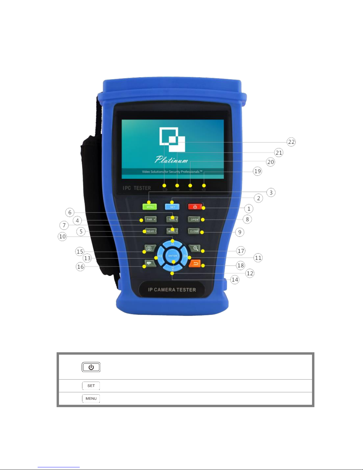
2.3 Function interface
1
Press more than 2 seconds, turn on or off the device, short press to turn on or off
the menu display
2 Set key
3 Menu key, press it to call shortcut- menu
Page 10
5
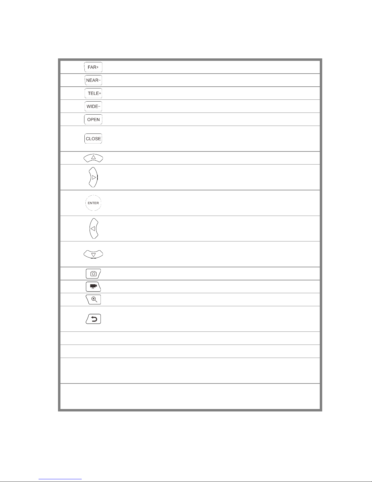
4 Near focus: Focus the image nearby
5 Far focus: Focus the image faraway
6 TELE: zoom in the image
7 WIDE: zoom out the image
8 Open/set, Confirm the setting of parameters, open or enlarge the aperture
9
Return/Close: Return or cancel while setting parameters of the menu, close or
decrease the aperture
10 Upward, set function or add parameter. Tilt the PTZ upward
11
Rightward, select the parameter whose value will be changed. Add the value of
the parameter. Pan the PTZ right
12 Confirm key (Long press it to capture screen interface)
13 Leftward, select the parameter whose value will be changed
14
Downward, set function or reduce the value of the parameter. Tilt the PTZ
downward
15 Snapshot
16 Video record
17 Open/set ,Confirm the setting of parameters, open or enlarge the aperture
18
Return/Close : Return or cancel while setting parameters of the menu, close or
decrease the aperture
19 The power indicator: it lights green while the tester is powered on by the adapter
20 The data accepted indicator: it lights red while the data is being received
21
The RS485/RS232 data transmission indicator: it lights red while the data is being
transmitted
22
The charge indicator: it lights red while the battery is being charged. As the
charging is complete, the indicator turns off automatically
Page 11
6
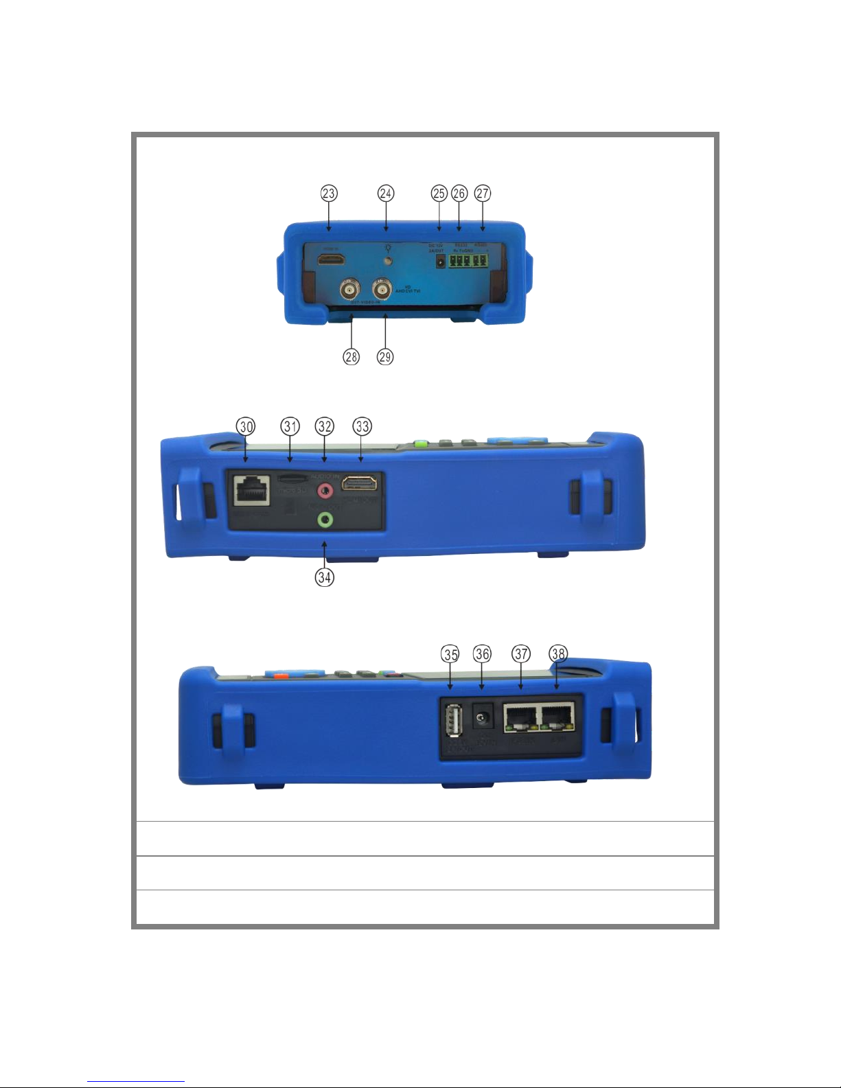
Top interface
Left interface
Right interface
23
HDMI input
24
LED lamp
25
DC12V2A power output , for provisional DC power supply
Page 12

7
26
RS485 Interface: RS485communication for the PTZ
27
RS232 Interface: RS232 communication for the PTZ"HD IN" , AHD /TVI/CVI Coaxial
interface
28
Video image signal output(BNC interface)/cable tracer interface (Optional)
29
Video image signal input(BNC interface)/ AHD,CVI and TVI input (BNC interface)
30
UTP cable port: UTP cable tester port/ Cable tracer port
31
Micro SD card moveable, comes with 8GB, supports up to 32GB
32
Audio input
33
HDMI output interface
34
Audio and earphone output
35
5V2A USB power output , as power bank
36
DC12V2A charging interface
37
PSE power sourcing equipment. Tests PoE voltage
38
PoE power supply output or LAN test port (Use to test PoE or non-PoE IP camera)
3. Operation
3.1 Installing the Battery
The tester has built-in lithium ion polymer rechargeable battery. The battery cable inside battery
cabin should be disconnected for safety during transportation!
Prior to the use of the instrument, the battery cables inside the battery cabin should be well
connected.
Pressing the key continuously can power on or off the tester.
Notice: Please use the original adaptor and connected cable of the device!
When the battery icon is full or the charge indicator turns off automatically, indicate the battery
charging is completed
Page 13
8
Notice: When the Charge Indicator turns off, the battery is approximately 90%
charged. The charging time can be extended for about 1 hour and the charging time within 12
hours will not damage the battery.
Notice :Press the key several seconds to restore the default settings when the
instrument works abnormally.
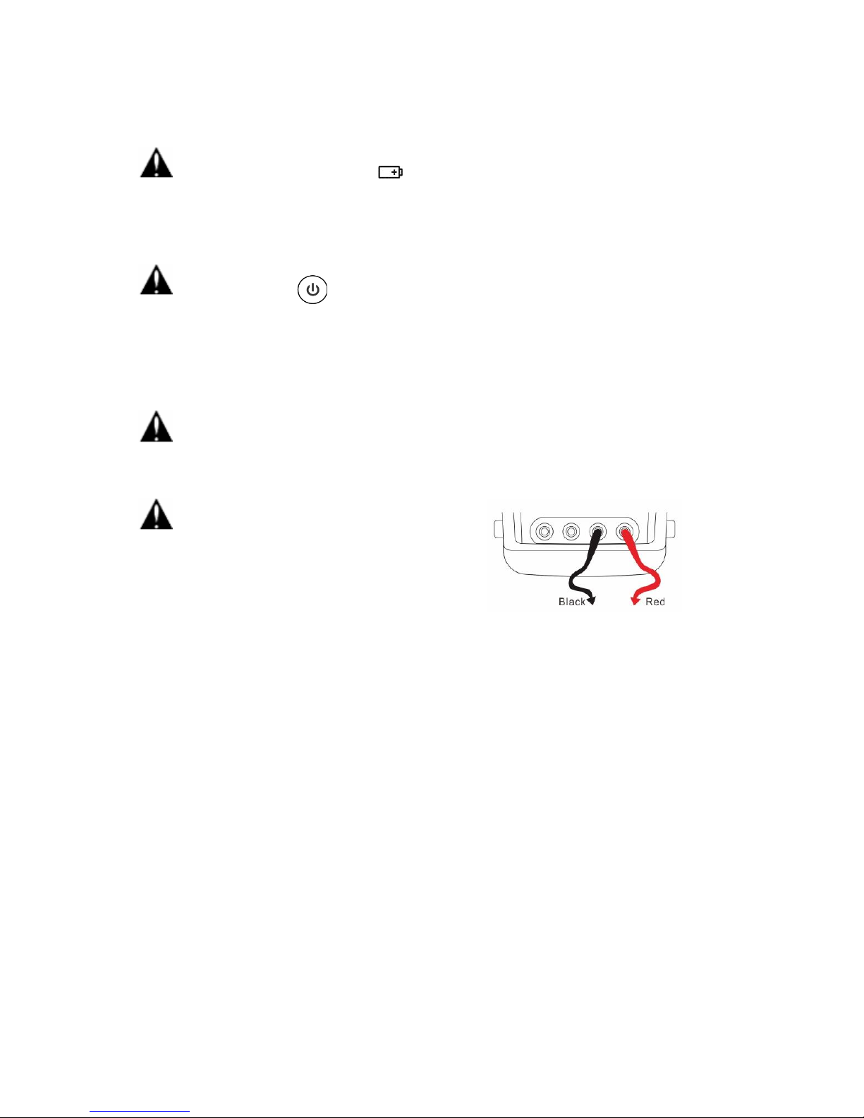
Multi-meter: the red and black multi-meter pen must insert the corresponding port.
Warnings: Instrument communication port is not permitted access circuit voltage over 6V,
otherwise damage the tester.
Warnings: Not allow insert multi-meter pen in the
current terminal to measure voltage
3.2 Instrument connection
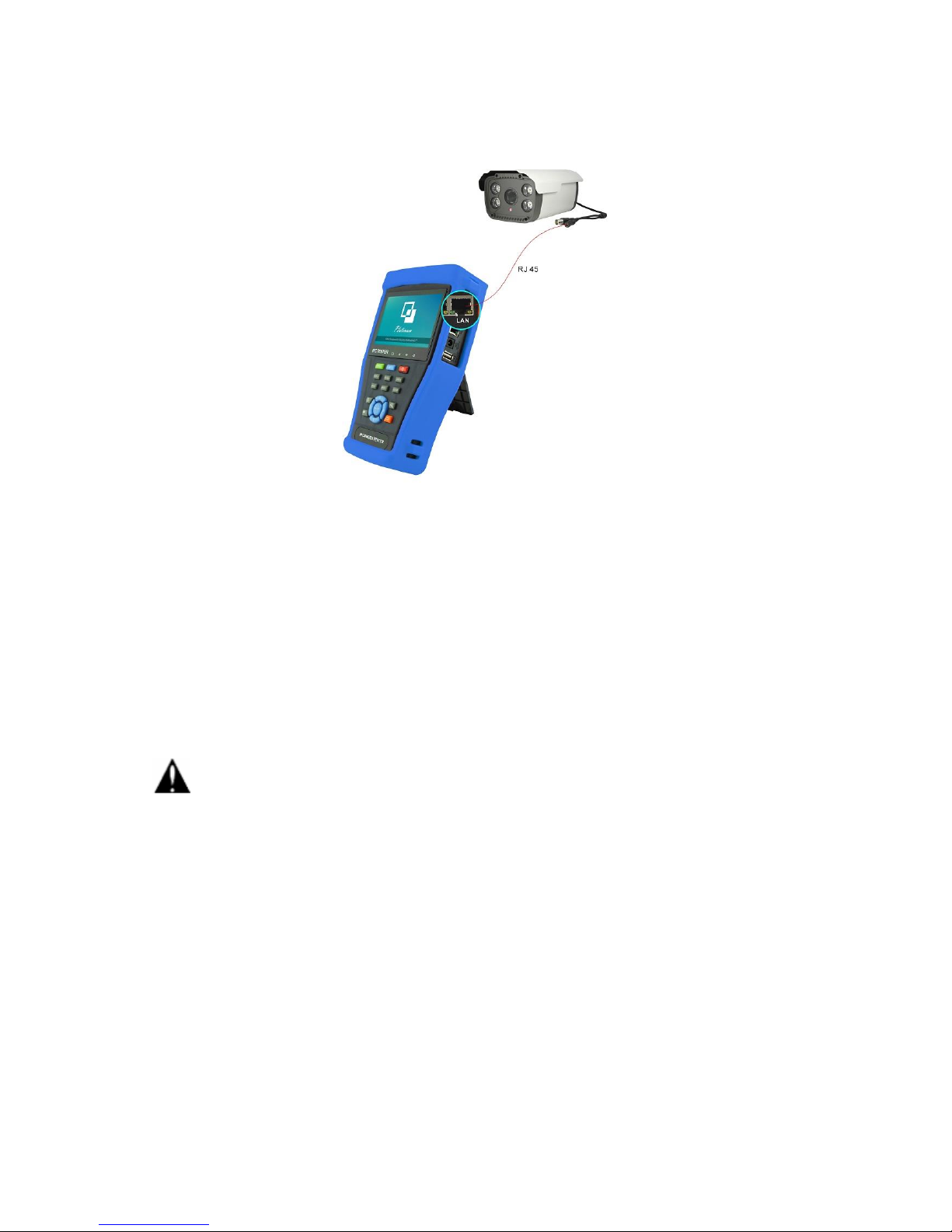
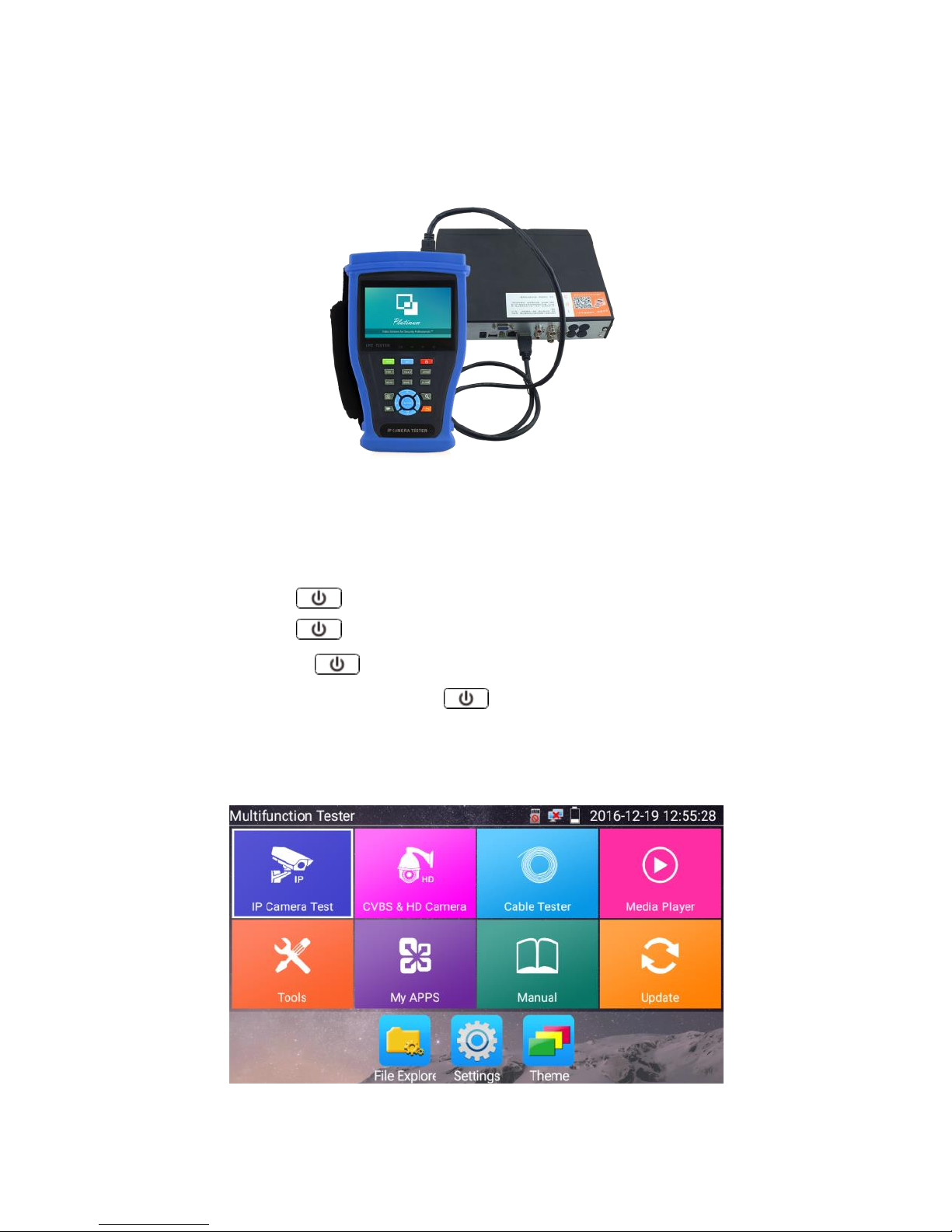
3.2.1 IP camera connection
Power an IP camera with an independent power supply, then connect the IP camera to the IPC tester’s
LAN port, if the link indicator of the tester’s LAN port is green and the data indicator flickers, it means
the IP camera and the IPC tester are communicating. If the two indicators don’t flicker, check if the IP
camera is powered on or the network cable is not functioning properly.
Page 14
9
Note:1) If the IP camera requires PoE power, then connect the IP camera to the IP tester’s LAN port .
The tester will supply PoE Power for the IP camera. Click on the icon labeled POE to turn the PoE
Power off or on.
2) If use the tester’s menu to turn off the tester’s PoE power supply, the PoE switch and the power
sourcing equipment are allowed to connect to the tester’s PSE port, and the PoE power will be
supplied to the IP camera by the tester’s LAN port. On this condition, the tester cannot receive data
from IP camera, but the computer connected to the PoE switch can receive the data via the tester.
Warning: PoE switch or PSE power sourcing equipment only can be connected to tester “PSE IN”
port, otherwise will damage the tester.
Page 15
10
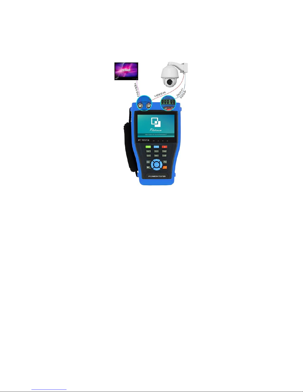
3.2.2 Analog camera connection
(1) Connect the camera's video output to the IP tester’s VIDEO IN. The image will display on the tester
after pushing the PTZ icon.
(2) CCTV IP Tester “VIDEO OUT” interface connect to the Video input of monitor and optical video
transmitter and receiver, the image display on the tester and monitor.
(3) Connect the camera or the speed dome RS485 controller cable to the tester RS485 interface, (Note
positive and negative connection of the cable). Support RS232 PTZ controller, connect the RS232cable
to RS232 interface of the tester.
Page 16
11
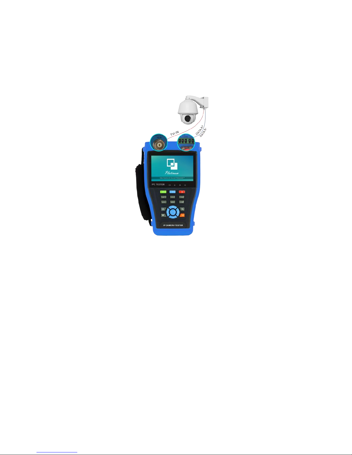
3.2.3 HD Coaxial camera connection
* CVI, TVI, AHD camera are classified as HD coaxial cameras. Hereby the following instruction of how
to connect TVI camera to the tester is also applied to CVI, and AHD camera.
(1) Connect the TVI camera's video output to the IP tester’s “TVI IN” interface, the image will display
on the tester. The tester only come with TVI input interface. There is no TVI output interface.
(2) Connect the TVI camera or the speed dome RS485 controller cable to the tester RS485 interface.
Support RS232 PTZ controller; connect the RS232 cable to RS232 interface of the tester.
Page 17
12
3.2.4 HDMI IN
DVR or other device’s HDMI in port connect to tester’s HDMI in port, the meter will display input
image.
3.3 OSD menu
Press the key 2 seconds to turn on
Press the key 2 seconds to turn off
short press the key to enter sleep mode, press it again to test if tester work abnormally
and cannot be turned off, Press the key several seconds to turn off, the tester reset.
3.3.1 Lite mode & Normal mode
Lite mode: You can easily find corresponding apps
Page 18
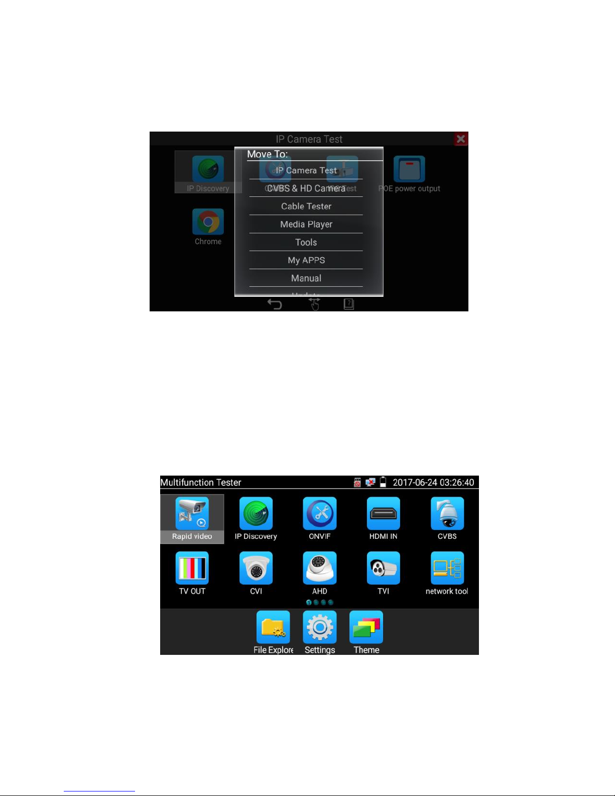
13
In Lite mode, press the icon for several seconds, then you can move the icon to other apps
In lite mode, click the finger icon in the lower right corner to release lock icon, move icons and
change function icons sequence.
Normal mode
Tap the screen and slide left or right to change menu.
Page 19
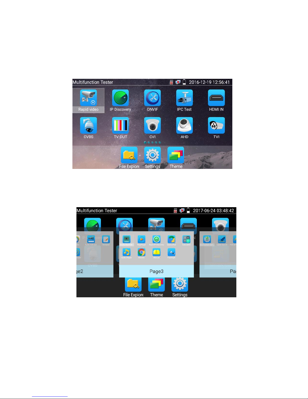
14
In normal mode, press icon several seconds, go screen management status. Change icons sequence
and move it to common tools bar.
You can move the icon to any pages, self-define the number of icons in any page. Make interface
simple and individualized.
Page 20
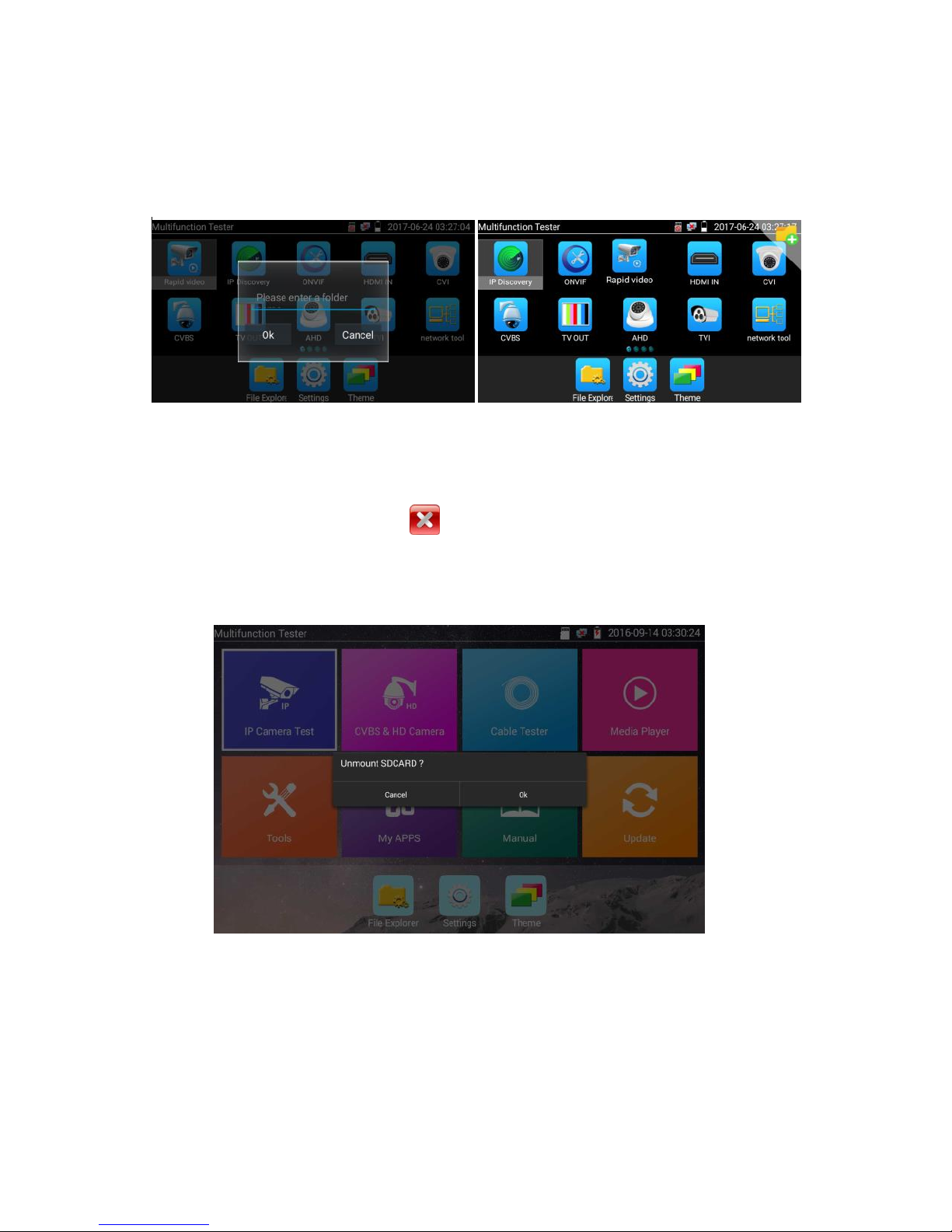
15
Create New Folder: Drag the icon to the folder in top right corner, enter the folder name. Icon will be
auto placed in the new named folder.
Press the folder several seconds, to change the folder name, you can move the icon out of folder, the
folder will be auto deleted until move out all icons.
Select Icons to enter, if quit, please click
Click SD card, install or remove SD card.
Page 21
16
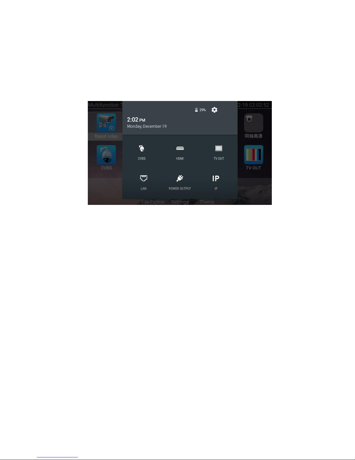
3.3.2 Drop-down Menu
Press and slide at right top right corner twice to open shortcut menu. The shortcut menu includes POE
power output, IP settings, Wi-Fi, HDMI IN, CVBS, Video OUT, LAN, Brightness, settings etc.
HDMI: Click HDMI IN to enter, In HDMI IN mode, it can convert test from analog to digital with
dual test window IP & HDMIN or Analog & HDMI in.
CVBS: Click icon “CVBS “to enter, you can test IP and analog camera at the same time.
TV OUT: Click Video OUT to enter floating window, connecting the BNC cable to tester and
appears analog video monitor interface, it can test circuit and BNC cable whether normal.
LAN: Display network port or WIFI connection real-time upload and download speeds and
other network parameters.
Brightness: Set brightness.
Settings: Enter settings interface.
IP: Enter IP Settings interface.
POE power output: Turn on or off the tester “PoE power “app.
WLAN: Turn on WLAN net and displays current WLAN status.
Page 22
17
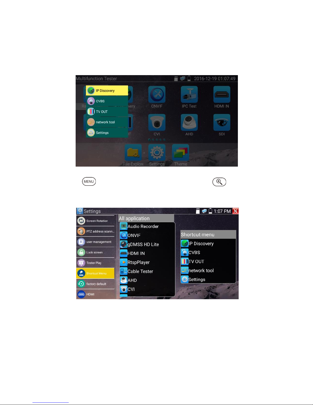
3.3.3 Short cut-menu
You can call shortcut –menu by press tester’s “menu” key, you can self- define shortcut -menu.
Press the key“ ”, you can turn on it and switch functions, then press to enter app, tap
other area on the screen, to exit the menu.
Short cut-menu setting, you can long press any app in the all applications list, it will auto move to
shortcut menu. If delete any app in the short cut – menu, please select a app and press several
seconds, it will be deleted.
Page 23
18
3.3.4 Screen capture
Long press the key “enter”, can capture screen interface and save it in any time.
You can go file management to view “file management –sdcard- Pictures—Screenshots.
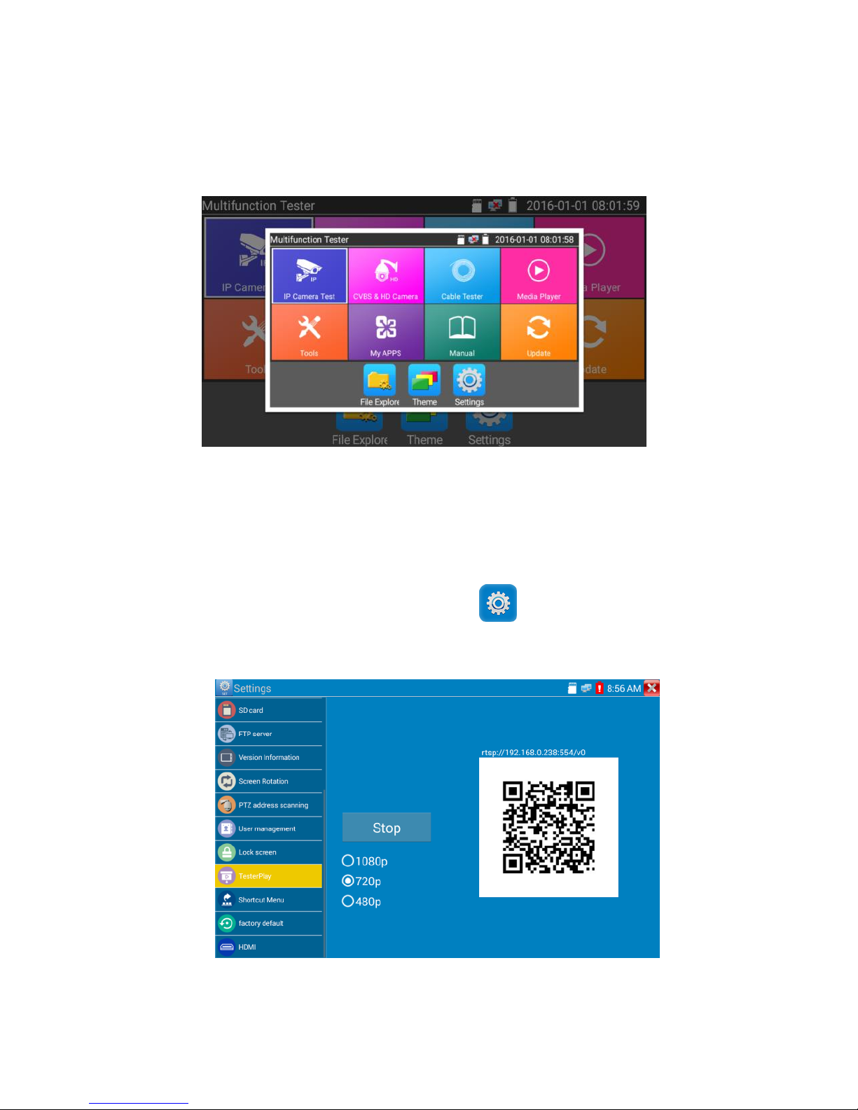
3.3.5 TesterPlay
Mobile screen projection (Only for android version)
The meter creates WIFI hotspot, connect mobile phone to the tester’s WIFI hotspot, or the tester and
mobile phone connect to the same Wi-fi network. Tap icon “ ”, then select “TesterPlay” app to
enter, click “Start” button to generates two-dimensional code, Please use mobile phone scan it, then
download and install the client software, you can view the screen real-time projection.
Page 24
19
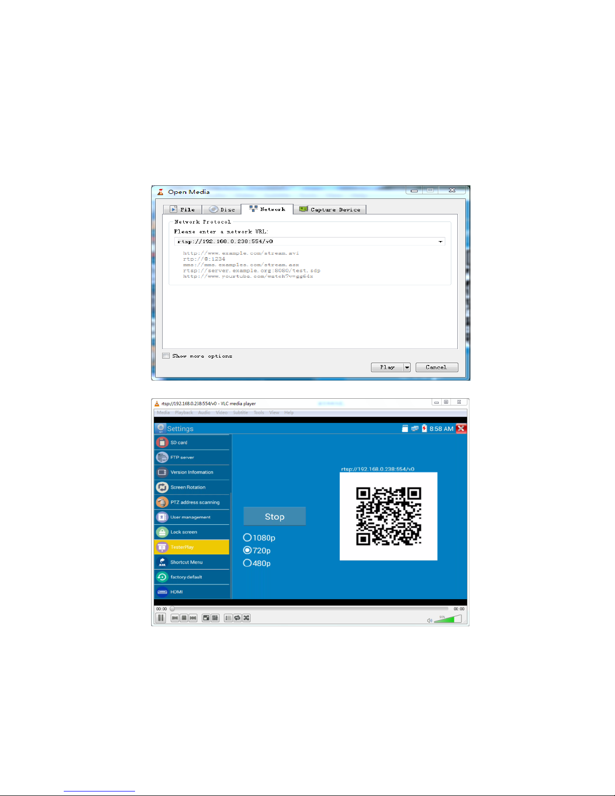
PC screen projection:
Install VLC player in the PC, turn on the VLC player "Media - Open Network Streaming", and
input the RTSP address of on the top instrument two-dimensional code, click "play" to view the
screen real-time projection.
Page 25
20
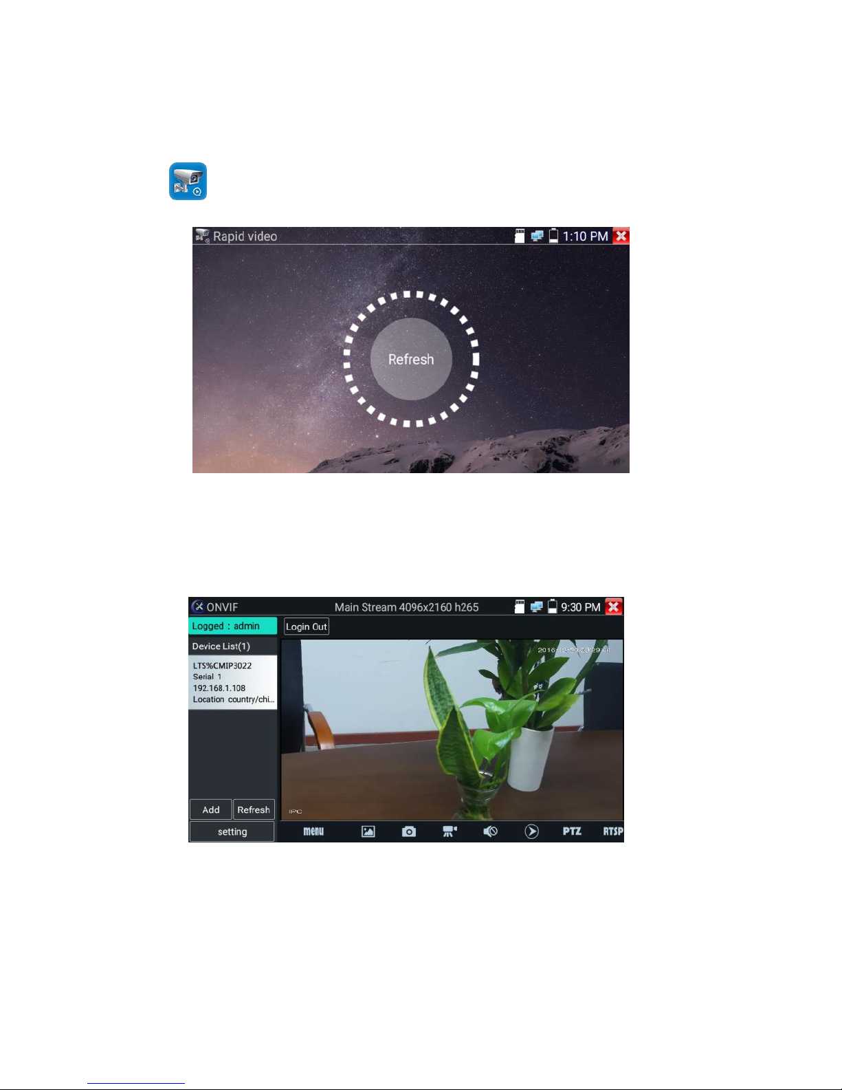
3.3.6 Rapid video
Press enter function, one key to detect all network cameras and auto play the images.
Auto log in and display camera image. Detailed operation refers to ONVIF function.
Page 26
21
After exit ONVIF app, Click Refresh to search IP address.
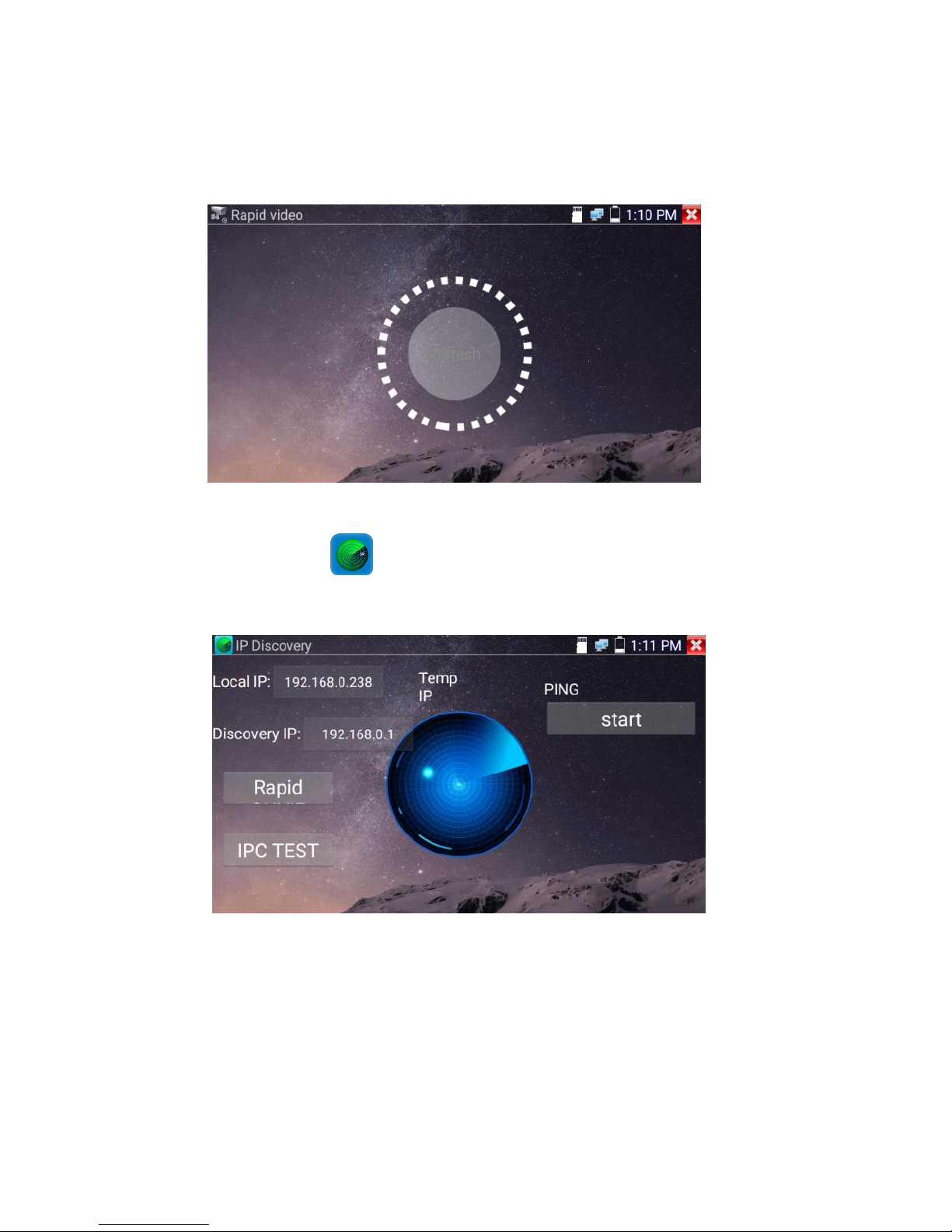
3.3.7 IP discovery
Press IP discovery , tester auto-scan the whole network segment IP, as well as
auto-modify the tester‘s IP to the same network segment with the scanned camera's IP.
Local IP:Tester’s IP address, Tester can auto-modify the tester‘s IP to the same network segment with
the scanned camera's IP.
Page 27
22
Discovery IP:Connected tester equipment’s IP address. If the camera connected to the tester directly,
tester will display the camera’s IP address, if tester connects to Local Area Network, it displays the
current IP address.
Temp IP:After searching IP address, the modified tester’s IP address will not be saved, if you do not
select “Temp IP,” the modified tester’s IP address will auto-save after searching.
Start:PING function, click "Start", can PING camera’s IP.
Rapid ONVIF: Rapid ONVIF Quick link
IPC TEST: IPC TEST Quick link
Applicability:Using IP discovery app, you don’t need to know the first two digits of camera’s IP
address, it can auto-scan the whole network segment IP, and auto-modify tester’s IP address, greatly
improved engineering efficiency.
3.3.8 Rapid ONVIF test
Rapid ONVIF can display 4K H.265/H.264 camera image by tester mainstream, one key to activate LTS
camera.
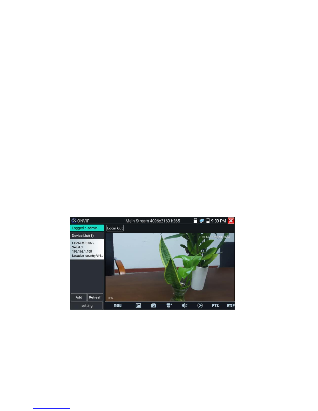
Press enter ONVIF function, the meter auto scans all ONVIF cameras in different network
segments. It lists cameras name and IP address on the left of screen. Tester can auto login camera and
display camera image. Factory default use admin password to auto login, if you modified the password,
then default use the modified password to login.
Page 28
23
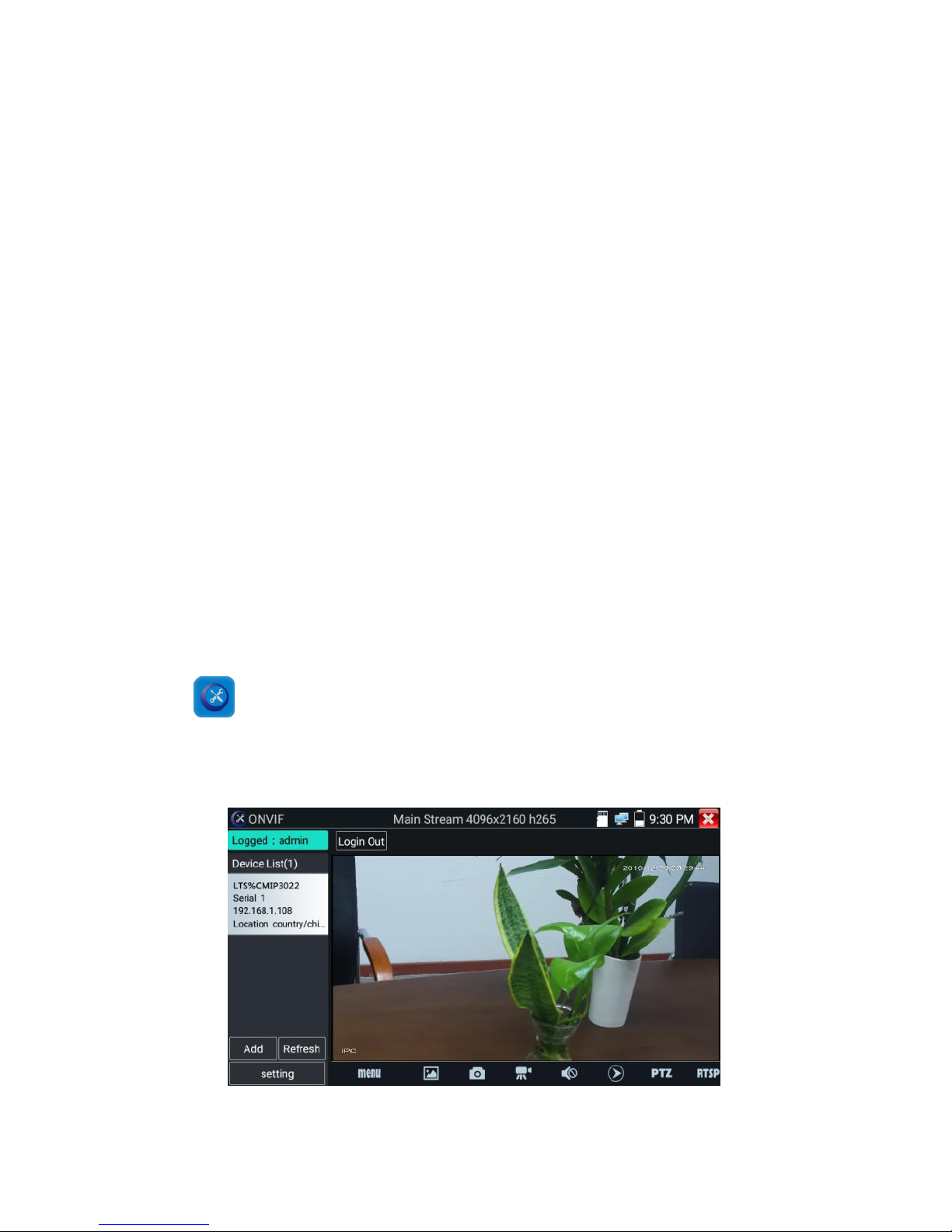
If you select ONVIF Rapid mode, the meter automatically scans different network segments for ONVIF
cameras. It lists the camera name and IP address on the device List. Tester can auto login camera and
display camera image.
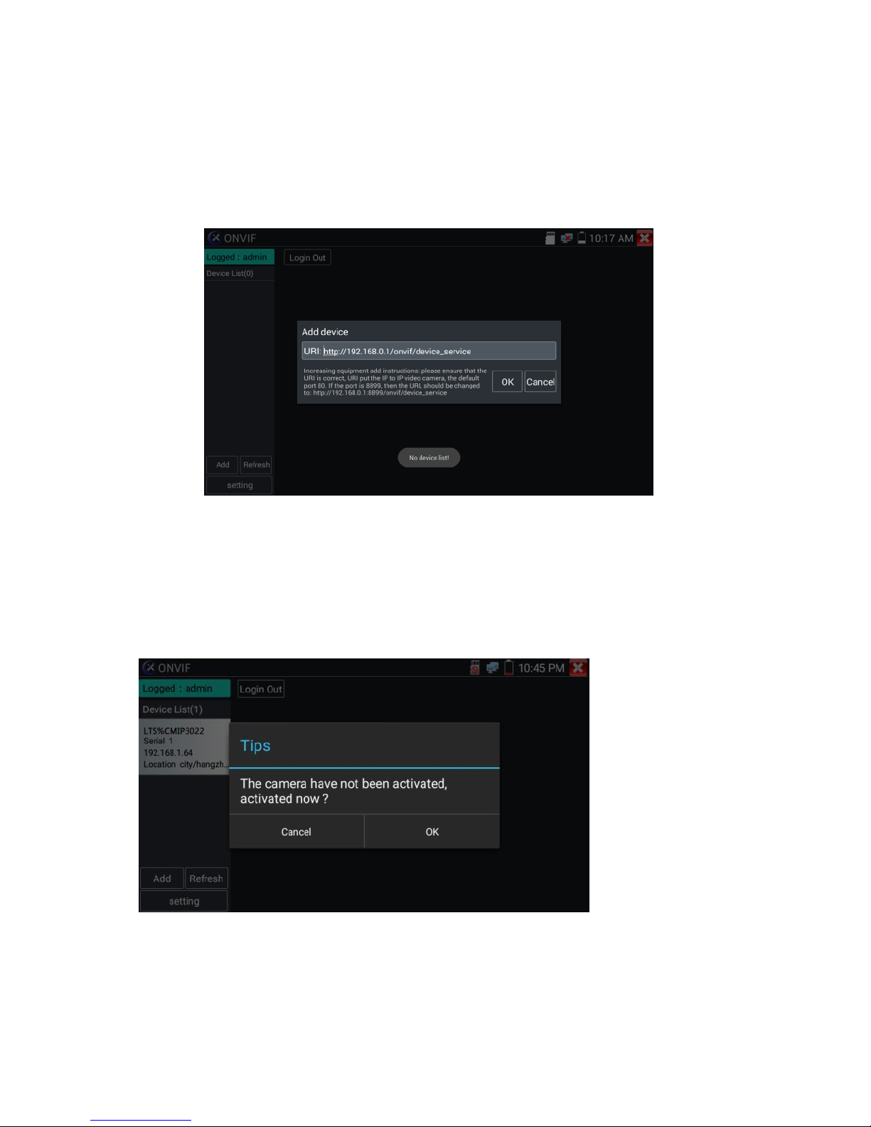
Click the button “Refresh”, tester will scan the ONVIF camera again. Click the newly displayed ONVIF
camera on the “Device List“. The tester will show the IP camera’s relative information and settings.
Activate LTS Camera: When connected inactivated LTS Camera, tester can auto recognize, and prompt
"The camera is not active, you need to activate it", click "OK" to start activating.
Page 29
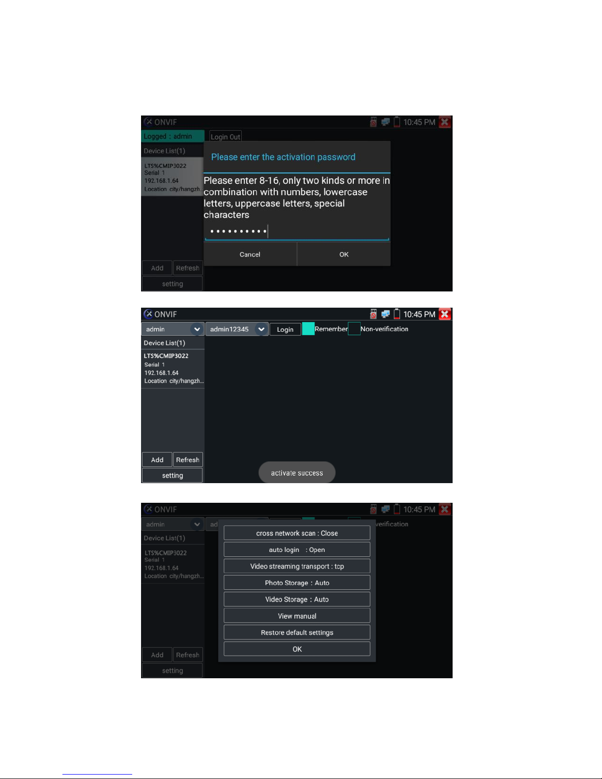
24
Enter a new password for the camera.
When comes out “activate success” prompt, click login to display camera image.
Pop-up settings menu when click the “ONVIF setting” icon in the upper left corner.
Page 30
25
Across network segments scan: After open this function, enter “Setting”-“IP Settings”-“Advanced “to
add other network segments IP, Rapid ONVIF function can across network segments to scan camera’s
IP.
Auto Login : After open this function, tester can auto login camera and display camera image (The
login password is the same with last time, the first time using password is the default password
"admin").
Video transmission protocol: UTP and TCP protocol
Open password cracker: Cracks password of cameras
View manual: Open Manual
Restore Defaults: Revert “Rapid ONVIF” to default settings
Confirm : Save the modified parameters
Click “MENU” icon to open camera setting.
Page 31

26
While in the “Live video” menu, click “Video Menu” at the top right of the image to access the
following tools: Snapshot, Record, Photo, Playback, PTZ and Settings.
ONVIF PTZ control: Tap the image in the direction you want the PTZ camera to move. Tap the left side
of the image to move left, right to go right, up to go up and down to go down. Compatible IP PTZ
cameras will rotate accordingly. PTZ rotation direction is displayed on top left corner of the image.
Page 32

27
IP camera video settings: Click “Video Set” to enter the IP camera’s encoder and resolution settings.
Make the desired changes and click “OK “to save.
Image setting: Click “Imaging Set” to adjust image brightness, saturation, contrast, sharpness and
backlight compensation mode.
Page 33

28
Profiles:Click “profiles",can view video streaming current configuration files, as well as switch
between Major stream and minor stream.
Preview pictures:Quickly preview and zoom in or out pictures, automatically and manual refresh.
Page 34

29
Identification: click “Identification” to view information of the camera.
Time set: click “Time set”, Select “Manual set" to set up the time of camera.
Maintenance: For camera software reset or restore to factory settings.
Page 35

30
User Set: Modify camera user name, password parameters.
Network setting:Click “Network Set “to change the IP address. Some cameras cannot support change
IP address, so there is no change after saving.
Page 36

31
Zoom in image: press the key to enter the zoom mode. Press it again to exit zoom mode.
When the image is enlarged, tap left, right, up or down on the image to move the whole image on the
screen.
When the image is enlarged, it can also be operated by keyboard .
Press the key to zoon in , press the key to zoom out , press upward and downward
key to move image.
If it is network video input to the tester, as the tester supports resolution up to 1080p, the input image
will be very clear after it is enlarged. This is greatly helpful for the installers to ensure the IP camera’s
video coverage and decide the IP camera’s install site.
Image can only be enlarged on SD mode (The icon “ONVIF” is SD mode.)
Select relative function on the bottom Toolbar to operate, “Snapshot“, “Record”, “Photos ”,
“Video playback”, “Storage set”, “PTZ control” etc.
Page 37

32
Snapshot:Click bottom “snapshot” to screenshot the image and store it to SD card.
if select manual storage, appears dialog box “Input Name” , user-defined the files name(by Chinese
character, English letter ,or digit ) to save in SD card, if select “Auto- storage”,the tester auto stores
the files after snapshot.
Record:When you click bottom the “Record” icon, video starts recording. A red recording icon
appears on the screen and begins to flash and a timer appears indicating the time elapsed for the
video. Click on the “Stop” icon to stop recording and save the video file to the SD card.
Playback:Click the “Playback” icon to view saved videos. Double click the video you want to play. Click
to return to the last menu.
Page 38

33
To rename or delete a photo, click and hold on the file until this screen appears:
Video files can play in the Video player on the main menu.
PTZ
Set preset position: Move the camera to preset position, enter the preset number on the bottom right
corner to complete position preset.
Call the preset position: Select the preset number on the left, click "Call" to call preset.
Page 39

34
PTZ Speed set: Horizontal and Vertical Speed set.
RTSP: Get RTSP address of the current camera.
Doc: Auto generate test reports document of camera, click "Create document”. Click Preview to view
the report document.
Page 40

35
Enter the camera test information; Click "Create Document" to complete the report.
click doc menu again, you can preview the report document.
Icons description: the description of function icons on the bottom toolbar.
3.3.9 IP camera test
Display image from the 4K H.265 camera by mainstream.
Click icon to enter IP camera test.
Note: Currently, the IPC Test App only supports some brands’ specific IP cameras, these include
specific models made by LTS, Hikvision, ACTI, AXIS, Dahua, Samsung, and many more. If the camera is
Page 41

36
not fully integrated, please use the ONVIF or RTSP apps.
IPC test interface
Local IP: This is the tester’s IP address. Click “Edit“ to enter “IP setting“ and change the tester ‘s IP
address settings.
IP camera type : Click on the IP camera type to select the Manufacturer and model number of the
integrated IP camera.
Manual:Click IP camera type, list LTS, Honeywell , Kodak, Tiandy, Aipu-waton, ACTi,WoshiDA IP
camera etc. If the brand has offered official original protocols, please select camera type, input IP
camera address ,user name and password ,click” official” to enter the camera image display
interface(Currently, only support DAHUA official protocols ).
Page 42

37
Stream code: When test camera via RTSP, you can select mainstream or sub stream to test (if
camera’s RTSP have not been start or without, it will tip “auto match fail, please switch to manually
selecting”.
IP Camera's IP: Enter the IP camera’s IP address manually or click “Search” to auto-scan for the IP
camera’s IP address. It is better to directly connect the IP camera to the tester so the search results
will only display the camera’s IP address. If the tester is connected to a PoE switch, it will find and
display several IP address.
IPC User Name: Enter IP camera’s user name.
IPC Password: Enter IP camera’s login password.
IPC Port: When you select the IP camera type, it will default the camera’s port number and doesn’t
need to be changed.
After all settings are completed, click “Enter” to view the live video.
Page 43

38
If IP address setting has error or IP camera is not connected. The tester prompts “Network Error”
Click to quit from image display and return to IP camera test interface.
Once you are viewing video on the IPC Test app, you will see the “Video Menu” icon on the top
right. This button will give you access to Snapshot, Record, Photo, Playback, PTZ, and Set. Please refer
to the ONVIF section to use these functions.
3.3.10 HDMI IN
HDMI in HD signal test, Tap icon “ ”to enter.
When tester receives HDMI in image, the top tool bar shows the resolution of this image. You can
select “resolution ” to set resolution in the setting menu .Tap screen by twice, full image display.
It supports resolution as follows :
720×480p /720×576p /1280×720p /1920×1080p /1024×768p/1280×1024p /1280×900p /1440×900p
(1) Snapshot
Click the icon “Snapshot “, when the video in, to take a picture and save the current video frame in the
SD card as JPEG file.
If the unit is set to the manual mode an “Input Name” pop up box will appear and you can enter a title
Page 44

39
for the snapshot. If the unit is set up to automatically set file names, this box will not pop up.
(2) Video record
When you click the “Record” icon, video starts recording. A red recording icon appears on the screen
and begins to flash and a timer appears indicating the time elapsed for the video. Click on the
“Record” icon again to stop recording and save the video file to the SD card.
if select manual storage, before recording begins ,appears dialog box “Input Name” ,user-defined the
files name(by Chinese character, English letter ,or digit) to store in SD card , tester will hereby store
the files in SD card after recording . if select “Auto-storage ,tester will auto store the files in SD card
after recording .
Page 45

40
(3)Photo
Click the icon “photo” to enter, click the selected thumbnail photo to display it on the screen.
Double-tap the image you want to view to make it full screen. Double-click again the photo to return.
To rename or delete an image, click and hold on the file until this screen below appears.
Click to close and return to PTZ controller.
Page 46

41
(4) Recorded video playback
Click the “Playback” icon to view your recorded videos. Tap on the video file image you want to watch.
To rename or delete a video, click and hold on the file until this screen appears:
Video files also can play in the main menu “Video Player".
Page 47

42
3.3.11 Video monitor test
Analog camera test and PTZ control, click icon to enter
Select relative function on the right side Toolbar to operate, functions including “Photos”, “Snapshot” ,
“Record” , “Playback” , “PTZ” , “Set” ,
Click , or press to quit.
Click the screen twice quickly, can be full zoom in on the touch screen.
(1) PTZ controller parameter setting
Select and click icon “PTZ”, to enter PTZ setting:
A. Protocol
Use the up and down arrow keys to move the yellow cursor to the “protocol ”, set corresponding
Page 48

43
Protocol and support more than thirty PTZ protocols. Such as
Pelco-D,Samsung,Yaan,LiLin,CSR600,Panasonic,Sony-EVI etc.
B. Port
Click and move, to “port” Select the communication port for the PTZ camera controlling (RS485).
C. Baud
Move the yellow cursor to “Baud”, Select the baud rate according to baud rate of the PTZ camera.
(150/300/600/1200/2400/4800/9600/19200/57600/115200)
D. Address
Set the ID according the ID of PTZ camera (0~254), the setting address data must be consistent the
speed dome address.
E. Pan speed: Set the pan speed of PTZ camera (0~63)
F. Tilt speed: Set the tilt speed of PTZ camera (0~63)
G. Set preset position (Set PS)
Click and select “Set PS”, set and save preset position number (1~128),
H. Call the preset position (Go ps)
Click and select “Set PS”, set and save preset position number (1~128), click “sure” to save,
Call some special preset number, can call the dome camera menu.
Check and set the protocols, address, interface and baud, all must be consistent with the dome
camera, then the IPC tester can test. After setting the parameter, the tester can control the PTZ and
lens.
To control PTZ by screen touch:
Tap left, right, upward and downward on the touch screen to control the PTZ rotation direction. By
two fingers move outward and inward on the touch screen to zoom in and out the PTZ.
Page 49

44
PTZ Control:
Press arrow keys to control to control the PTZ direction of
rotation
Press the key to switch on or turn off the aperture.
Press the key , adjust the focus manually
Press the key , manually adjust the zoom
2) Video and storage setting
Click icon “set”, to enter and set analog video image brightness, contrast, color saturation, as well as
the file storage way after snapshot and recording, support auto-storage and manual storage.
When select manual storage, user can name and store the files.
(3) 4 x zoom image display and Video out
When image input, press to enter “zoom”, press it again to quit.
Using the touch screen to control PTZ camera movement:
Tap left, right, upward or downward on the video image to move the PTZ camera in a desired direction.
Stretch two fingers outward or inward on the touch screen to zoom the image in or out.
Page 50

45
If not use touch screen to operate, press the key to zoom out, press the key to
zoom in, press upward and downward key to move the image.
For analog video input, as the resolution is 720*480, it is normal that the zoom in image is not
clear. But for network digital video input, as it supports resolution up to 960*540, the zoom in image
is still very clear. This is very helpful for IP camera installation.
(4) Snapshot
Click the icon “Snapshot “, when the video in, to take a picture and save the current video frame in the
SD card as JPEG file.
If the unit is set to the manual mode an “Input Name” pop up box will appear and you can enter a title
for the snapshot. If the unit is set up to automatically set file names, this box will not pop up.
Page 51

46
(5) Video record
When you click the “Record” icon, video starts recording. A red recording icon appears on the screen
and begins to flash and a timer appears indicating the time elapsed for the video. Click on the
“Record” icon again to stop recording and save the video file to the SD card.
if select manual storage, before recording begins, appears dialog box “Input Name”, user-defined the
files name (by Chinese character, English letter, or digit) to store in SD card , tester will hereby store
the files in SD card after recording . if select “Auto-storage, tester will auto store the files in SD card
after recording.
(6)Photo
Click the icon “photo” to enter, click the selected thumbnail photo to display it on the screen.
Double-tap the image you want to view to make it full screen. Double-click again the photo to return.
Page 52

47
To rename or delete an image, click and hold on the file until this screen below appears.
(7) Recorded video playback
Click the “Playback” icon to view your recorded videos. Tap on the video file image you want to watch.
To rename or delete a video, click and hold on the file until this screen appears:
Page 53

48
Video files also can play in the main menu “Video Player".
3.3.12 Color-bar generator (TV OUT)
Click to enter, the tester sends the color bars from the “Video out” port ,Click the icon “PAL”,
select “PAL/NTSC” output formats.
Click the selected color-bars, testing image or single bar ( red, green, blue, white or black). Double click
to full display on the screen and output, click to return main menu.
Application
BNC loop test: Tester can send and receive color bar generator through the tester’s “video out and
Page 54

49
video in” port, it is for testing transmission channels, such as video Optical, video cables etc. The tester
“VIDEO OUT” port to connect optical terminal’s sending port, and “VIDEO IN” Port to optical terminal’s
connect its receiving port.
A. When maintaining the dome camera, the tester sends out the color bar by its BNC output to the
monitor at the monitoring center. If the monitor receives the color bar, it means the video transmit
channel works normally. Meanwhile on the basis of the received color bar, the monitoring center can
judge if transmission has loss or interference.
B. The tester sends out the pure color bar (such as white and black color), to test the monitor whether
has bright or black dots.
C. The tester sends out video signal image to test if the image received by the monitor has excursion.
3.3.13 CVI camera test
HD CVI camera, CVI dome camera test and PTZ control, click icon to enter
When HD CVI signal input, the tester will display the image resolution on the top bar. Double-taps on
the screen to make the image displayed full screen.
The tester supports resolution as follows
1280x720P 25FPS / 1280x720P 30FPS / 1280x720P 50FPS / 1280x720P 60FPS
1920x1080P 25FPS / 1920x1080P 30FPS/2560x1440P 25FPS/2560x1440P 30FPS.
Page 55

50
(1)PTZ control
1.1 Coaxial PTZ control
Click the icon“PTZ”on the right toolbar to do the corresponding setting.
“Port”: select coaxial control
Page 56

51
Enter PTZ address to perform parameters setting
Operation instructions, please refer to “3.3.1 PTZ (1) Video monitor test”.
The PTZ address in the tester must be consistent with the dome camera or decoder, then the
IPC tester can test. After setting the parameter, the tester can control the PTZ and lens.
To control PTZ by screen touch:
Tap left, right, upward and downward on the touch screen to control the PTZ rotation direction, PTZ
cameras will rotate accordingly. By two fingers move outward and inward on the touch screen to
zoom in and out the PTZ.
To control PTZ by key buttons
Page 57

52
Press arrow keys to control to control the PTZ direction of
rotation
Press the key to switch on or turn off the aperture.
Press the key , adjust the focus manually
Press the key , manually adjust the zoom
Set preset position:
Move the PTZ camera to the preset position, the Tap it and input preset position number. Tap “Set
position” to complete set preset position.
Call preset position
Tap the preset position:
Tap the preset position area, input preset position number. Tap “call position” to complete call preset
position.
Page 58

53
1.2 RS485 control
Operation instructions, please refer to “3.3.1 PTZ (1) PTZ control parameters setting”.
(2)Coaxial camera menu setting
Tap icon “UTC””, select “menu setting” to enter the dome camera menu.
Input calling dome camera menu address code, after finishing the parameter settings, you can press
the key or click the icon to call the dome camera menu.
Page 59

54
Press arrow keys to set
(3) Snapshot, record, photo viewer and video play back, please refer to “3.3.1 PTZ (1) Video monitor
test”. Tap “close menu” or press the key “ ”to close camera menu.
Page 60

55
(4) Save setting
Click icon “Set” on the right toolbar to enter storage setting.
Support auto-storage and manual storage.
When select manual storage, user can name and store the files.
3.3.14 TVI camera test
HD TVI camera, TVI dome camera test and PTZ control, Click icon to enter
When HD TVI signal input, the tester will display the image resolution on the top bar. Double-taps on
the screen to make the image displayed full screen.
The tester supports resolution as follows:
Page 61

56
1280x720P 25FPS / 1280x720P30FPS / 1280x720P 50FPS / 1280x720P 60FPS
1920x1080P 25FPS / 1920x1080P 30FPS / 1920x1080P 50FPS / 1920x1080P 60FPS /2048x1536P
18FPS/2048x1536P 25FPS/2048x1536P 30FPS /2560x1440P 15 FPS/2560x1440P 25 FPS/2560x1440P
30 FPS/2688x1520P 15FPS/2592x1944P 12.5FPS/2592x1944P 20FPS
Coaxial camera menu settings
Tap icon “UTC”, select “menu setting” to enter the dome camera menu.
Page 62

57
Input calling dome camera menu address code, after finishing the parameter settings, you can press
the key or click the icon to call the dome camera menu.
More operation instructions (such as PTZ control, coaxial camera menu setting, snapshot, recording
and playback etc), please refer to“3.3.6 CVI camera test”.
3.3.15 AHD camera test
AHD camera, AHD dome camera test and PTZ control, Click icon to enter
Page 63

58
When AHD signal input, the tester will display the image resolution on the top bar. Double-taps on the
screen to make the image displayed full screen.
The tester supports resolution as follows:
1280x720P 25FPS / 1280x720P 30FPS / 1920x1080P 25FPS / 1920x1080P 30FPS/2048x1536P
18FPS/2048x1536P 25FPS/2048x1536P 30FPS /2560x1440P 15 FPS/2560x1440P 25 FPS/ 2560x1440P
30 FPS/2592x1944P 12.5FPS/2592x1944P 20FPS
(1) Coaxial PTZ control
UTC control : select “PTZ control or PTZ control-2”(AHD camera has two different order ,if select “PTZ”
cannot control , please go “PTZ-2” ).
If to coaxial PTZ control the AHD camera, no parameters setting is needed.
Page 64

59
More operation instructions please refer to “3.3.6 CVI camera test”.
3.3.16 Network tool
(1)IP address scan
Connect the cable to the LAN port, click icon to enter, Set your IP address search range by
changing the Start and End IP addresses. Click the “Start” button to scan the IP address range. You can
also input an IP address in the Port Number Scan to scan for open ports.
(2)PING Test
Connect a network cable to the LAN port and click the icon to open the PING tool. You can set
your LOCAL (native) IP address, Remote IP address (e.g. IP camera), Packet count, Packet Size, Packet
time and Timeout. Press “Start” to start pinging. If the IP camera or network device is not configured
properly or not plugged in, it will say “Destination host unreachable,” or have 100% packet loss. If the
tester connects to the device, the send and receive packets will have a 0% packet loss.
Page 65

60
Application: PING testing is the most conventional network debugging tools. It is used for testing if the
connected IP camera or other network equipment’s Ethernet port is working normally and the IP
address is correct.
It’s normal that the first data packet will be lost when test start.
(3)Network test (Ethernet bandwidth test)
Network test (Ethernet bandwidth test)
To use the Network tester, you will need two IP testers. One is used as a Server and the other as a
Client. Both devices must be on the same network segment in order to communicate. Click the
icon to open the Network Tester app.
a).Start the server: Click “Start Server” button to use the tester as a Server. It will display its IP address
at the top of the screen.
Page 66

61
b). Start send packet test: Using the other IP tester, type in the Server's IP address at the top right
corner of the screen. This app is used to send packets for network speed testing. Click the “Start”
button to send the packets and start testing.
Network bandwidth testing can also be tested with a computer using compatible network bandwidth
testing software. Install network bandwidth testing software on a computer, as a test Client or Server,
to do the mutual testing with the tester. If use computer as the server, the computer IP address
is :192.168.0.39.
Tester as Client, tester’s IP address is:192.168.0.238. The Server and the Client are at the same
network segment, but with different IP address. Input Server’s IP address 192.168.0.39 in the tester
Page 67

62
and click “Start” to test network bandwidth.
Or use tester as a Server, computer as test Client(select Client, input tester’s IP address to test).
When use tester as Server, shows results:
Page 68

63
(4)Port Flashing
Connect a network cable to the meter’s “LAN” port, click the icon to open the Port Flashing
app. Click “Start”. The IP tester sends a unique signal to make the connected LAN port of the switch
flash.
If the tester and PoE switch are connected well, the LAN port of POE switch flash at special frequency,
If not, no any changes on the LAN port.
Application:
The tester will send special signals to make the connected LAN port flicker at special frequency, which
will enable the installers to easily and quickly find the connected Ethernet cable. This function can
prevent mistakenly insertion or disconnection non-corresponding cable to artificially interrupt
network connection.
Page 69

64
(5)DHCP server
Click on the DHCP icon to open the DHCP server app. Select the “Start” check box at the top and make
any desired changes to the network settings. Click “Save” to start assigning dynamic IP addresses for
IP cameras and other networked devices. Click the “Refresh” button to check your Client list.
(6)Trace route
It is used to determine path of the IP packet access target.
Note: Trace route testing results only for reference, for accurate test route tracking, Please use
professional Ethernet tester.
Click to enter trace route
Input tracking IP address or domain name in the Remote Host IP. Set maximum hop count, normally
default is 30.
Page 70

65
Click “start” to trace the goal address
(7)Link monitor
Click the icon to open the Link Monitor app. This app is used to see if an IP address is occupied
by other network devices. This will avoid new address conflicts.
Click “Add” and enter the desired IP address. To test different network segments, click the “Settings”
icon on the main menu and go to IP Settings and make the desired changes. Once the desired IP
addresses are added to the Link Monitor list, click “Start”. If the IP address status shows a check mark
the IP address is occupied. If the IP address status shows an X the IP address is available. Click “Stop”
to stop the testing.
Page 71

66
Application:
Add an IP camera or other network device to the current network group, the new IP address must not
be occupied, otherwise it will result IP conflicts and stop the equipment normal working. Link monitor
can check if the new setting IP address is occupied.
3.3.17 Rapid IP Discovery
Connect the cable to tester’s LAN port. Press to enter Rapid IP Discovery app.
Click “Start “to search all IP address of connected equipments in whole network segment.
Click “Stop “to stop work.
3.3.18 PoE power / DC12V 2A and DC 5V 2A USB power output
When the tester is turned on, the DC12V and DC5V power output functions are automatically turned
on. If the IP tester is turned off, the 5VDC USB can still be used to power an external USB device.
To use the PoE Power Output function, click on the icon and change the switch “ON” or “OFF”.
The IP camera needs to be connected to the LAN port before you turn PoE Power on. If the IP camera
Page 72

67
Supports PoE, the PoE power is delivered via pins 1, 2, 3, and 6 on the LAN port. The IP tester will
display “48V ON” at the top of the screen when the POE power is still on.
Note:
1. Don’t input power into the “DC12/2A OUTPUT” port.
2. Don’t output this DC12V/2A power to the DC12V/IN port of the IP camera tester to avoid destroy.
3. The IPC tester power output is close to 2A, if the IP camera’s power is over 2V, the tester will auto
enter protection mode. Disconnect all the connections of the tester and then connect the tester
with power adaptor to resume the tester.
4. Before turning on the PoE power output, please make sure the IP camera supports PoE power.
Otherwise it may damage the IP camera.
5 Make sure you plug in your IP camera to the LAN port prior to turning on PoE power.
6. Make sure the tester is full charged or more than 80% charged, otherwise the tester will show
“low power”, “not able to supply power”.
Page 73

68
3.3.19 Cable Test
Click icon to enter
Test LAN cable or telephone cable.
Connect LAN cable or telephone cable with the CCTV tester and cable tester. And then the
connecting status, cable type and the sequence of wires as well as the serial number of the cable
tester kit will be displayed.
The number of the cable tester is 255.
If need several different number other types cable testers, should pay the additional cost.
Tap "cable test sketch map”, pop up Straight-through cable and crossover cable sketch, It is for line
sequence reference ,when the crystal on the first pressure in the twisted-pair.
Page 74

69
3.3.20 RJ45 cable TDR test
Connect cable to tester’s LAN port, click icon “ ” to enter RJ45 cable TDR test app.
Single test: Test cable status, length and attenuation.
Repeat test: Continue to test cable status, length and attenuation.
Status: After link up, screen display “online”, if not link up or open circuit, screen display” open
circuit”, if cable pair is short circuit, screen display “short circuit”.
Length: The max test length is 180 meters, when cable is open circuit or short circuit, can test
the cable length, if screen display “online”, the testing result would be not accurate.
Cable quality test: Green is good quality cable, Yellow is Poor quality cable, Red is water
poured cable, the attenuation value will be displayed when cable over 10 meters.
Page 75

70
Advanced Test: Test cable pair status, length, attenuation, reflectivity, impedance, skew and
another parameter.
Attenuation reflectivity: After linking up, if reflectivity value is 0, it is the best quality
communication.
Impedance: After linking up, if the impedance value is 100 Ω, it is the best quality
communication, the range is generally in 85-135 Ω .
Skew: After 1000M link up, when skew value is 0ns,it is the best quality communication, if over
50ns, will cause a Bit Error Rate in the transmission.
Connection diagram
Page 76

71
Cable sequence diagram:
A straight- through and cross-over cable diagram, the cable sequence display for reference
Click “Help”, check the instruction of all parameters.
3.3.21PoE voltage and power measurement
Click icon to enter PoE voltage measurement .
Page 77

72
Connect a network cable from a PoE switch to the IP tester’s PSE IN port. Connect an IP camera or
other PoE using node to IP tester’s LAN port, the PoE voltage and the cable’s pin connection status
show on the screen.
Note: This test is for measuring the voltage being drawn by the PoE node and the IP tester
must be between the PoE switch and the PoE node for this test to work.
Note: The PoE switch must be connected to the PSE IN port. The powered device such as IP
camera or other PoE node must be connected to the LAN port.
Note: Do not connect PoE power supply equipment (such as a PoE switch) to the tester’s
UTP/SCAN port; otherwise it will damage the tester.
PSE transmission
When PoE / PSE voltage testing, PoE/PSE connect to the tester's PSE "IN" port , the camera connect to
tester's Lan port , tester not only can transmit voltage to supply power for camera ,but also transmit
data at the same time. as well as the computer connect to the PoE/PSE, it can log in connected tester's
PoE camera.
3.3.22 12V power input test
Connect 12V power adaptor to tester’s charging port, then click icon “PoE” to enter voltage
Page 78

73
measurement app, screen show the current adaptor input voltage and power. Note: the
current 12V input measured power is the battery charging power and the device working
power, the measured power will change depending on the different of battery power and
backlight brightness.
Warning: Not allow connect device with input power over 17V to tester “12V IN“ port,
otherwise it will damage the machine.
3.3.23 Audio Record
Connect an audio device to the IP tester’s audio input port. Click the icon to enter the Audio
Recorder app. Click the red button to stop, and the unit will prompt you to save the recording.
Page 79

74
3.3.24 Data monitor
Please click icon to enter
Click “Setting” to choose the baud rate of RS485/RS232; it must be the same as the DVR or the Control
keyboard. The DVR or Control keyboard send the code to the tester, if it can be read, the protocol will
shown on the upper right, like Pelco D, if not, like P:---
While the tester receives the code, press the key to empty.
Though the RS485 port, display the PTZ control code of the multifunctional keyboard or the DVR.
Controller can check the status of the RS485 transmission through the code on the display. (The RS485
communication rate must be the same.)
Application: Check the RS485 communication states of the video optical transmitter whether normal.
Engineer can analyze the protocol and check the data through the displayed code.
3.3.25 Audio player
Click the icon to enter . The audio player only supports MP3 format Audio files.
Page 80

75
3.3.26 Media Player
Click the icon to enter
The Media player can browse video and image files. It supports the video formats of MP4, H.264,
MPEG4, and MKV. The IP tester recorded files can play directly via the Media player. The Media player
will automatically display the video files from the SD card. Click on the desired file to play. Click
RETURN to exit.
To rename or delete an existing file, press the file name for a few seconds until the screen below
appears. You can then rename or delete the file by pressing the desired option.
3.3.27 RTSP Player
The RTSP Player app will allow you to view the RTSP video stream from an IP camera. If you were
unable to view your camera via the ONVIF or IPC Test apps, it is possible your camera will have an
Page 81

76
RTSP stream and you can view live video.
From the main menu, select the “APP Tool” folder and then select the “RTSP Player” to open the app.
If the IP camera uses MJPEG, select the RTSP icon. If the IP camera uses H.264, select the “RTSP HD”
icon.
Local IP: This is the IP testers IP address.
RTSP Add: This is where you can manually enter the IP camera’s RTSP URL or click on Search to search
the network for cameras that use an RTSP stream.
IPC Username: Enter the IP camera’s user name.
IPC Password: Enter the IP camera’s password.
Once you have entered all the necessary information, select Enter at the bottom left to view the RTSP
stream.
Page 82

77
Note: in the event the IP tester does not auto detect the RTSP stream, refer to the specific camera
manufacturer for the specific RTSP stream URL. you may find this on line with a search of the
camera model number and the word RTSP.
3.3.28 NVMS7000
Activate LTS camera, display image from the camera, modify IP, user name and password parameters etc.
Click the icon to enter the app.
Please refer to "Help" for detailed instruction
Page 83

78
3.3.29 Update
Copy the downloaded update file to SD card "update" directory, if no directory, please create one.
Click the icon to open the Update menu. Select “Local Update” to update via the SD card or
select “Online Update” to check for updates on the internet. If there are applications that need
updating, the applications will be displayed on the
If there are update programs, applications will be listed in the interface, click related applications,
update to the latest version.
3.3.30 Office
Quick office app (support excel, word, ppt format) doc. editable
Page 84

79
3.3.31 LED Flashlight
It is convenient for the installation or maintenance in the evening or in the dark. Click icon to
enter
While in the flashlight app, click the red button to turn on the LED lamp. Press it again to turn it off. If
you don’t press the red button to shut off the lamp and press the button to exit the app, the
lamp will stay on. Click the Time Setting button to set a timer that will shut off the lamp.
3.3.32 Browser
Click icon to enter
Type in the camera’s IP address and press “Go” to access the IP camera’s interface.
NOTE: You will not be able to view live video in the web browser. For viewing video, use the IP
tester‘s live camera view Apps
Page 85

80
The IP camera and IP tester be on the same network segment for the browser to interface with the
camera. If they are not in the same segment, click the button or press “RETRUN” to exit. Open
the “Settings” app from the main menu to change the IP tester’s network settings to match those of
the IP camera.
3.3.33 Notepad:
Notepad can be used to record the important testing results, click the key “Save” to save the contents.
Notepad can auto record the storage date and time.
.
Please click to view the notepad , all saving contents display. Click each record bar to show the
details. Press the record bar for several seconds, prompt whether delete it.
Page 86

81
3.3.34 System Setting
Click icon to enter
Language: Select your desired language: English, Chinese, Korean, Russian, Italian, Polish, Spanish,
French or Japanese.
Typewriting: You can select typewriting or install other typewriting:
Date/Time: Set the Date/time of the IP tester.
Page 87

82
IP setting: Manually set the IP address, Subnet Mask, Default Gateway and DNS address or select
“Dynamic allocation” to use DHCP.
WLAN Net: Turn WiFi off or on by pressing the “Open the WiFi” button. Once WiFi is turned on, and
click connected WIFI, it will scan for wireless networks in your area.
Select and press “WIFI” several seconds, to set static IP address.
Page 88

83
Wi-Fi hotspot: input “SSID” name and “password”, and then click “ok” to create Wi-Fi hotspot.
Brightness: Set the desired brightness of the IP tester and adjust the sleep time settings.
Volume: Set volume level
SD Card: Displays SD Card Capacity. You can also format the SD card or unmount it before removing it.
FTP server: Once the IP tester connects to a network, a computer can be used to read the SD card files
via FTP.
Page 89

84
Start the FTP server and then input the tester’s FTP address in the PC’s address bar. This will enable
the PC to read, copy and edit the files from the SD card without the use of SD card reader.
Version information: Shows applications version information, if press any apps icon several seconds to
uninstall.
Screen display rotation: Click on “Screen Rotation” to flip the IP tester’s display 180 degrees. This
function is very convenient for the user to connect the LAN cable on the bottom of the unit without
having to flip the unit itself.
PTZ address scan: You can toggle the PTZ Address scan off or on before entering the “PTZ controller”
app. This needs to be turned on to use the PTZ Scan feature of the PTZ app.
Online Registration: Online update need register first, after the tester connect to network, then fill
registration information to register.
User Feedback: If you have any comments or suggestions for the tester, please connect it to network
and write your feedback.
Lock Screen: The meter default is not locked. You can choose password Lock screen, pattern Lock
screen or “NO” .
Password Lock Screen: Set password, you can input digitals, letters or characters as password, input it
again to confirm. When the meter is in standby mode or turn it on, you can input your password to
enter.
Pattern Lock Screen: Drawing a pattern to lock. While the meter is in standby mode or turn it on, you
Page 90

85
can input your pattern to enter.
Modify Lock screen password, you need input lock password again. Select password Lock screen or
pattern Lock screen to reset lock screen password. After reset pattern lock screen, you need to draw a
new lock pattern.
Restore the factory settings: If the tester to restore factory settings, all your personal files and apps
will be removed.
3.3.35 File explorer
Click “File “on the top bar tool, can select internal or external storage. Click on the upper right corner
Icon”... “.will pop-up menu, you can select other operation or exit .
Browse
It includes Music, Videos, Pictures, Documents, zip file etc. It is convenient to view and manage.
Page 91

86
FTP server
You can choose internal or external SD card.
Other operation details, please refer to FTP settings
Page 92

87
3.3.36 Theme
Click Theme icon to enter themes setting.
Desktop style: you can select Lite mode or normal mode.
Theme:
Pressing square area’s any color icon several seconds, the selected color icon will be auto move the
rectangle area, if you press selected color several seconds, and it will be auto deleted.
Theme colors include fixed order and random order, and click “set” to save .
Color
When set background color, you can select colors from Color Phase, and can input color’s RGB to set.
Page 93

88
After finished color setting, click “set” to set it as desktop or application background.
Set as desktop background: Setting color as desktop background.
Set as application background: Set color as application background.
Set at the same time: Setting color as desktop background and application background.
Cancel: Cancel current setting.
Picture:
Click Picture to select one, and set as temporarily background to view setting effect. Click “more” to
select pictures from local file, and click set to set picture as background.
Page 94

89
Sliding effect:
Tester’s sliding effect includes stereo effect, folding effect, Left and right folding, rotate effect, Ombre
effect etc, selecting one of effect to view slide effect in the square area, and click “set” to save.
3. 4 Audio test
You can test the audio input from audio pickup devices by connecting the audio pickup device to the IP
tester with the supplied audio cable.
Page 95

90
3.5 PoE power output
The IP tester supports PoE (Power over Ethernet) output to an IP camera via the LAN port. Data
transmission and 48VDC use the network cable’s 1, 2, 3, and 6 pins to deliver power. If the IP camera
supports PoE, you can directly connect to the camera without the use of an external power supply.
Notice
a. Please make sure the cable connected to the tester’s Lan port is straight-line cable and has no short
circuit, otherwise will damage the tester.
b. Before using PoE power output, please check the IP camera whether supports POE powered.
Otherwise .
it will damage the IP camera.
c. The instrument’s PoE maximum power output is 24W. If Ultra- high-power load happens, the tester
will enter protection mode .
3.6 HDMI output
The built in HDMI output port can output live video from an analog or IP camera, recorded files, media
files and images to HDTV monitors. Connect an HDMI cable from the IP tester to an HDTV monitor at
Page 96

91
any time. It supports up to 1080P resolution.
3.7 DC12V 2A power output
When the IP tester is turned on, the DC 12V power output ON by default. The smaller end of the
supplied converter cable connects to the tester’s DC12V/2A OUTPUT and the other end connects to
the camera’s power input.
Application
Power output function is mainly used in the camera field demonstration and testing, meanwhile, for
some camera installation sites, if there is no power outlet for the adapter to power the camera, the
tester can offer temporary power for it. But we do not suggest tester supply power for a long time.
Notice:
a. Don’t input any power into the “DC12/2A OUTPUT” port of the tester.
b. Man-made damage is not within our company’s warranty.
c. The IP tester‘s power output capacity is 2A. If the IP camera uses more than 2A, the tester will
Page 97

92
automatically enter a protection mode.
d. Disconnect all cables from the tester and reboot it to resume using the tester.
The IPC tester power output is close to 2A, if the IP camera’s power is over 2V, the tester will
auto enter protection mode. Disconnect all the connections of the tester and then connect the
tester with power adaptor to resume the tester.
e. Make sure the tester has a sufficient charge otherwise the tester will not able to provide enough
output power.
3.8 USB 5V 2A power output
When the tester is turned on, the 12VDC and 5VDC power output functions are automatically turned
on. If the IP tester is turned off, the 5VDC USB can still be used to power an external USB device.
NOTE: The USB port is for power only and not data.
Page 98

93
4. Specifications
4.1 General Specifications
Model
LTA-X48M
Display
New 4.3 inch IPS touch screen CCTV tester 960x540 resolution
Network port
10/100/1000M auto adjust, RJ45
WIFI
Built in WIFI,speeds150M, allows you to connect to a wireless network and
view IP cameras
H.265 Main stream
test
New hardware decoding,4K,H.265/H.264 camera image display by
mainstream testing
IP discovery
Auto-scan the whole network segment camera IP
Rapid ONVIF
Search camera quickly, auto log in and display image from the camera,
activate LTS camera
IP camera type
ONVIF,ONVIF PTZ, LTS CMIP3022, Dahua IPC-HFW2100P, Samsung
SNZ-5200, Tiandy TD-NC9200S2, Kodak IPC120L, Honeywell HICC-2300T,
RTSP Viewer
TVI video signal test
1 channel TVI input(BNC interface),resolution support 720p
25,30,50,60fps/ 1080p 25,30fps /2048x1536p 18,25,30fps , 2560x1440p
15,25,30fps/ 2688x1520p 15fps , 2592x1944p 12.5,20fps UTC control and
call OSD menu
CVI video signal test
1 channel CVI input(BNC interface, resolution support 720p
25,30,50,60fps/ 1080p 25,30fps/2560x1440p 25fps,30fps
AHD video signal test
1 channel AHD input(BNC interface),resolution support 720p 25,30fps /
1080p 25,30fps/2048x1536p 18,25,30fps , 2560x1440p 15,25,30fps/
2592x1944p 12.5,20fps UTC control and call OSD menu
Analog video test
1 channel BNC Input & 1 channel BNC Output , NTSC/PAL (Auto adapt)
Zoom Image
Supports Analog and IP camera image zooming & movement
Page 99

94
Snapshot, Video
record and playback
Capture current images and record live video as JPG file. Media player will
view photos and playback video
HDMI IN
Support 720x480P/60fps720x576P/60fps,1280x720P/25/30/ 50/60fps,
1920x1080P/25/30/50/60fps,1920x1080I/50/60fps,800x600P/60fps,
1024x768P/60fps,1280x1024P/60fps.
HDMI output
1 channel HDMI output, supports up to 1080p
12V/2A power output
Output DC12V/2A power to camera
RJ45 cable TDR test
RJ45 cable TDR test and cable quality test, to test cable pair status, length,
attenuation reflectivity, impedance, skew and other parameter.
USB 5V power output
5V 2A power output only ,NO data
PoE power output
48V PoE power output, Max power 24W
Screen management
Lite mode and normal model available. Under normal mode, you can
change icons sequence and self-define the number of icons in each page
Theme
Self-define icons, desktop and application interface background, modify
interface sliding effect
Drop-down menu
Includes PoE power switch ,IP setting, WLAN switch , HDMI IN functions etc
screen lock, password lock screen or pattern lock
Audio test
1 channel audio signal input and 1 channel audio signal output to connect
headphones
PTZ control
Support RS232/RS485 control, Baud 600-115200bps, Compatible with
more than 30 protocols such as PELCO-D/P, Samsung, Panasonic, Lilin,
Yaan, etc
Color bar generator
Output one channel PAL/NTSC color bar video signal for testing monitor or
video cable.(red, green ,blue, white and black color )
UTP Cable tester
Test UTP cable connection status and display on the screen. Read the
number on the screen
Data monitor
Captures and analyzes the command data from controlling device, also can
Page 100

95
send hexadecimal
Network test
IP address scan, link scan, and Ping test. Quickly search the for IP camera’s
IP address on your network
PoE /PSE voltage test
Measures PoE switch voltage and displays pin configuration
POWER
External power supply
DC 12V 2A
Battery
Built-in 7.4V Lithium polymer battery ,5000mAh
Rechargeable
After charging 5~6 hours, normal working time 10 hours
Parameter
Operation setting
OSD menu, select your desired language: English, Chinese, Korean,
Russian, Italian, French, Polish, Spanish, Japanese etc
Auto off
1-30 (mins)
General
Working Temperature
-10℃---+50℃
Working Humidity
30%-90%
Dimension/Weight
215mm x 127mm x 53mm / 0.82kg
The data above is only for reference and any change of them will not be informed in advance. For
more detailed technical inquiries, please feel free to call the Technical Department of our company.
 Loading...