

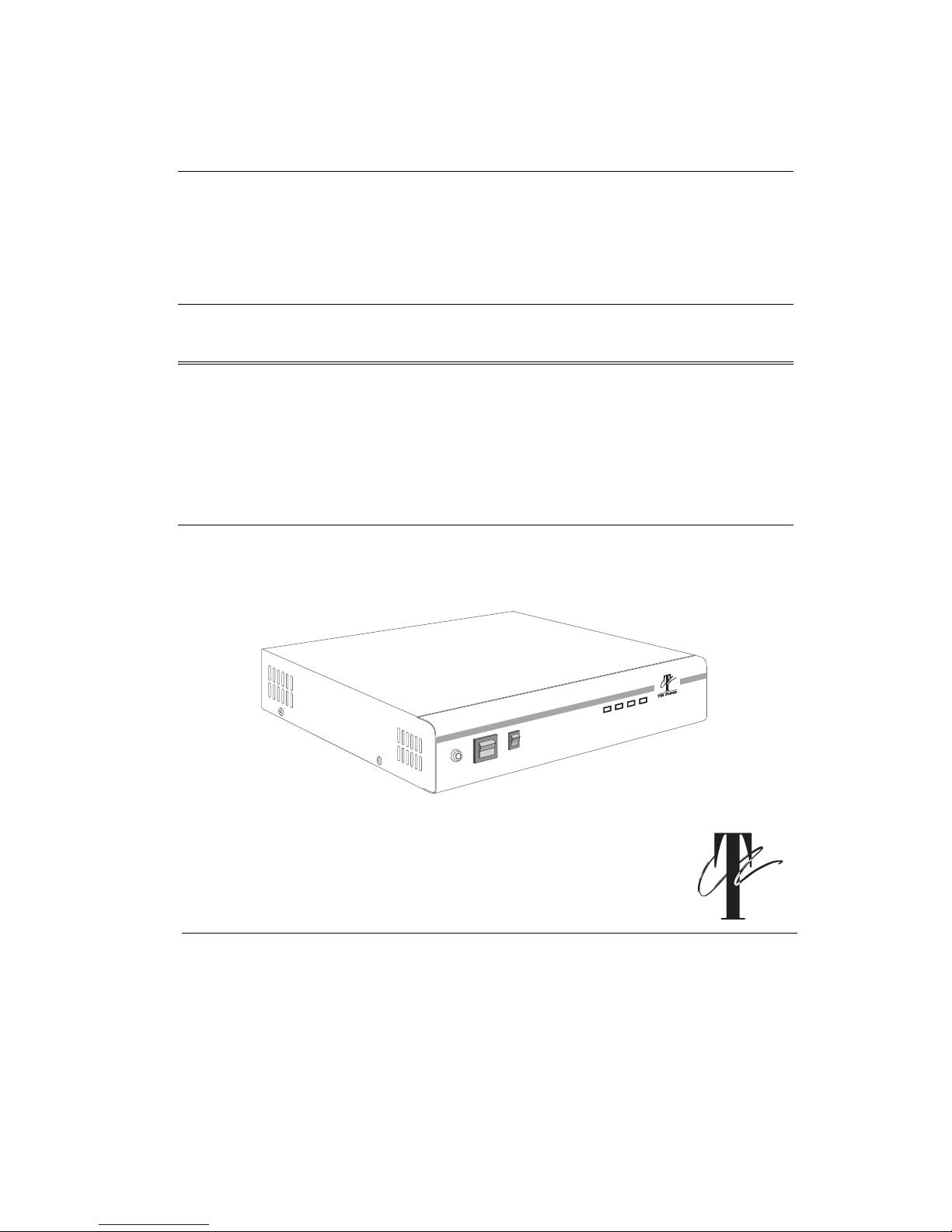
TSi Power UPS-550B, UPS-720B Operating Instructions Manual
TSi POWER
Operating Instructions
UPS-550B
UPS-720B
ALARM
ENABLE
POWER
REMOTE
NORMAL
ON
REMOTE
DISABLE
OFF
AC ON BAT CHRG
INDICATORS
REMOTE
INV ON
UNINTERRUPTIBLE POWER SUPPLY
UPS-7200
Uninterruptible Power Supply
Internet: www.tsipower.com e-mail: sales@tsipower.com
Other company’s product names herein are for identification purposes only and may be trademarks of their respective companies.
TSi POWER CORPORATION
1103 West Pierce Avenue
Antigo, WI 30071, USA
Phone: (715) 623-0636 FAX: (715) 623-2426
© Copyright—2000 TSi Power Corporation. All rights reserved.
TSi Power’s ongoing product improvement process makes specifications subject to change.

SAVE THESE INSTRUCTIONS
This Manual Contains Important Safety
Instructions.
CONSERVER CES INSTRUCTIONS
Cette Notice Contient Des Instructions
Importantes Concernant La Sécurité.
This manual contains important instructions for models
UPS-550B and UPS-720B that should be followed during
installation and maintenance of the UPS and batteries.
Nominal Battery Voltage of the battery supply inside the
UPS is 24 volts.
Maximum Operating Ambient Temperatur e for the UPS
and Battery Extension Unit is 40 degrees Celsius
When you are using the rack, cabinet or wall mounting
kits, please see the section on Installation Procedure for
Mounting Kits for important safety information.
© Copyright—2000 TSi Power Corporation. All rights reserved.
TSi Power’s ongoing product improvement process makes specifications subject to change.
Other company’s product names herein are for identification purposes only and may be trademarks of their respective companies.

Table of Contents
Quick Installation ................................................................................... 1
Front Controls & Indicators.................................................................... 2
Rear Controls & Functions ..................................................................... 3
About Your UPS...................................................................................... 4
Features of your TSi Power UPS.............................................................. 4
Detailed Operating Instructions .............................................................. 5
Network Installation & Alarm Interface .................................................. 6
Remote UPS Access................................................................................. 8
Typical Holdup Times........................................................................... 10
Trouble-shooting and Maintenance....................................................... 11
UPS Technical S pecifications................................................................. 12
Installation Procedure for Mounting Kits .............................................. 13
i
© Copyright—2000 TSi Power Corporation. All rights reserved.
TSi Power’s ongoing product improvement process makes specifications subject to change.
Other company’s product names herein are for identification purposes only and may be trademarks of their respective companies.

Quick Installation Guide
To get the UPS up and working immediately, please follow these instructions:
¨ Unpack the UPS from the box. Save the packing material for future use.
¨ Place the UPS at a convenient location, within 6 feet of an electrical
outlet and near the equipment you want backed up. Be careful, it’s
heavy!
¨ Plug one end of the detachable AC power cord to the rear of the UPS
(marked “AC IN”)
¨ Plug the other end of the AC cord into an 120V/60Hz electrical outlet.
You should now see the green AC ON light turn on in front of the UPS.
¨ Plug in your equipment to the outlets provided at the rear of the UPS.
Please, no laser printers, refrigerators or space heaters!
¨ Remove the shipping tape from the large power on/off switch in the
front of the UPS, and turn the UPS on. All your equipment hooked up
to the UPS should now be ready to power up.
Quick Installation Guide
1
Other company’s product names herein are for identification purposes only and may be trademarks of their respective companies.
Congratulations! You’ve already taken a large step toward protecting your
valuable equipment from potential power problems. We suggest however
that you read the rest of this manual to derive the most benefit from your
investment in TSi Power’s UPS’s. If you’ve encountered any problems in this
quick installation procedure, please read on. You can also refer to the
troubleshooting guide on p. 14.
© Copyright—2000 TSi Power Corporation. All rights reserved.
TSi Power’s ongoing product improvement process makes specifications subject to change.
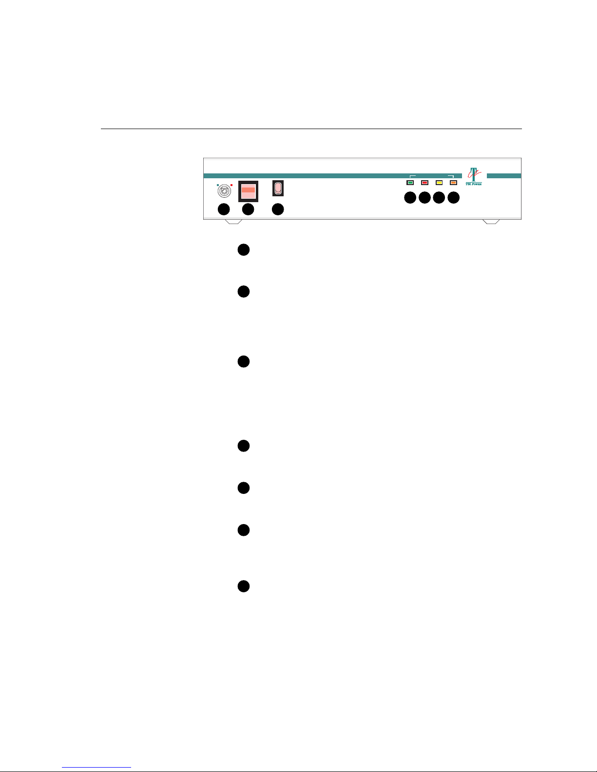
Front Controls & Indicators
NORMAL REMOTE
Note: Some models may
not be equipped with all
the features shown.
See p. 8 for more information about
Remote UPS Access.
¨
B C
¨
POWER
ALARM
ON
ENABLE
DISABLE
OFF
A
INDICATORS UPS-7200MODE
AC ON BAT CHRG
INVON
REMOTE
GFED
UNINTERRUPTIBLE POWER SUPPLY
A Power Switch
Use this switch to turn the UPS on.
B Mode Key Switch (some models)
With this switch in the NORMAL position, UPS operates normally.
When this switch is in the REMOTE position, power is supplied to the
equipment only when the telephone line is active.
C Alarm Switch
With this switch in the ENABLED position, alarm will sound when AC
outage occurs. When this switch is in the DISABLED position, alarm is
disabled. However, when battery voltage is low, alarm will sound
regardless of the position of this switch.
D AC On Light
This green light is on when AC power is present.
2
Other company’s product names herein are for identification purposes only and may be trademarks of their respective companies.
E Battery Charging Light
This red light is on when battery is being charged.
F Inverter On Light
This yellow light blinks when AC power is abnormal and UPS is
operating on battery.
G Remote Mode Light (some models)
This orange light blinks when UPS is placed in REMOTE mode using
the REMOTE switch.
© Copyright—2000 TSi Power Corporation. All rights reserved.
TSi Power’s ongoing product improvement process makes specifications subject to change.
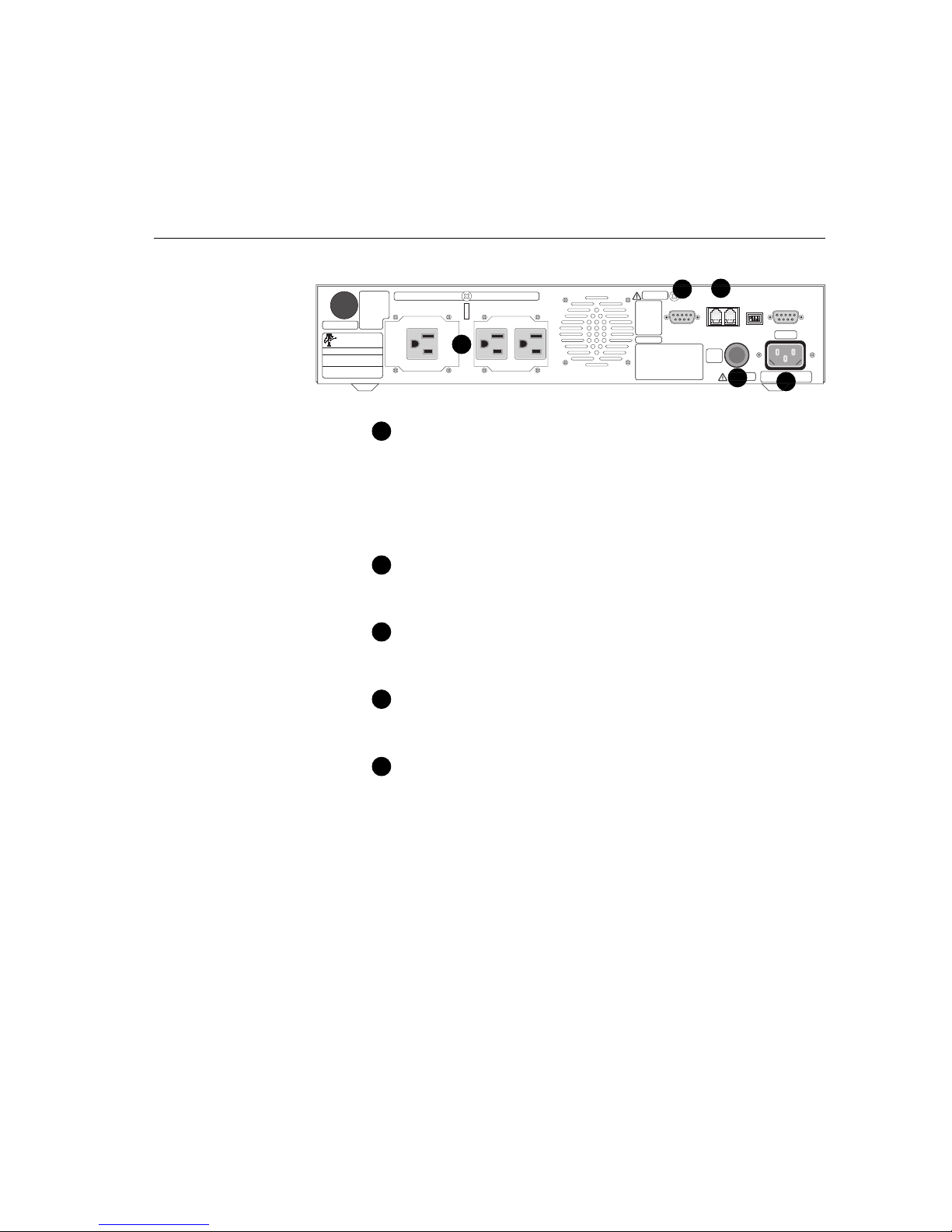
Rear Controls & Functions
TO EXT-5000
UPS-7200
AC INPUT:
UPS OUTPUT:
DC IN/OUTPUT:
SERIAL NO.
MADE IN U.S.A.
CAUTION
TURN OFF POWER
SWITCH DURING
BATTERY EXTENSION CONNECTION.
FOR DISCONNECT
USE ONLY. NOT
INTENDED FOR
CURRENT INTERRUPTION.
UNINTERRUPTIBLE
POWER SUPPLY
120V, 60HZ, 7A MAX, P.F.=1
120V, 60HZ, 4.2A MAX, P.F.=1
24V, 30A MAX
U P S O U T P U T
A
D
WARNING
ALARM
TO REDUCE THE
RISK OF FIRE OR
INTERFACE
ELECTRIC SHOCK,
54321
INSTALL IN A
TEMPERATURE
9876
AND HUMIDITY
CONTROLLED
AREA FREE OF
CONDUCTIVE
CONTAMINANTS.
CAUTION
THIS UPS RECEIVES POWER FROM MORE THAN
ONE SOURCE—DISCONNECTION OF THE AC
SOURCE AND THE DC SOURCE IS REQUIRED TO
DE-ENERGIZE THIS UNIT BEFORE SERVICING.
DO NOT REMOVE COVER. NO USER SERVICEABLE
PARTS INSIDE. REFER SERVICING TO QUALIFIED
PERSONNEL.
HAZARDOUS LIVE PARTS INSIDE THIS UPS ARE
ENERGIZED FROM THE BATTERY SUPPLY EVEN
WHEN THE INPUT AC POWER IS DISCONNECTED.
E
REMOTE CONTROL
MODEM LINE
125V 7A
AC
FUSE
WARNING
E
F
S
U
F
E
F
S
U
B
BAUD
RATE
ON
1234
B1 B2 B3 B4
U
S
E
RS-232
INTERFACE
54321
9876
AC IN
FOR CONTINUED PROTECTION
AGAINST FIRE, REPLACE ONLY WITH
SAME TYPE AND RATING OF FUSE
C
If you are not sure about how much
¨
power your equipment draws, see
accompanying table, “Load Ratings
for Typical Equipment”
See p. 8 for more information
¨
about Remote UPS Access
A UPS Output Receptacles
Outlets for the equipment to be supported by the UPS. The power
drawn from these receptacles should not exceed 360 watts for UPS-550B
and 500 watts for UPS-720B.
B AC Fuse
Replace only with same type and rating.
C AC IN Socket
AC mains power input connector. International standard CCE-22 type.
D Alarm Interface (some models)
Connects to a file server, PC or workstation for UPS monitoring.
E Remote Control (some models)
Dual RJ-11 phone and modem connectors for remote access. Connect
the incoming phone line to LINE connector, other phone equipment
(telephone, fax, modem etc.) to the MODEM connector.
Rear Controls & Functions
3
Other company’s product names herein are for identification purposes only and may be trademarks of their respective companies.
© Copyright—2000 TSi Power Corporation. All rights reserved.
TSi Power’s ongoing product improvement process makes specifications subject to change.
 Loading...