

Page 1

MODEL 8691-2
FUME HOOD SENSOR AVERAGING VENTING KIT
INSTALLATION INSTRUCTIONS
This Sensor Averaging Venting Kit can be installed with all TSI Fume Hood Face Velocity Controllers and Face
Velocity Monitors.
Prein stallation
Installation will be substantially easier if the side wall
of the fume hood can be removed prior to Sensor
Venting Kit installation. If the side wall cannot be
removed, there is usually an access panel inside the
fume hood that needs to be removed. This should
allow enough room to maneuver the tubing.
Parts List (Figure 1)
One T-fitting Assembly w/sensor housing
20 ft.1½" ID Tubing
One extra-long sensor cable
Two mounting flanges (black)
One bag with:
One O-ring
Four screws
Four clamps
Two brackets
Two self-tapping nuts
Step 4: Mount the MOUNTING FLANGE to the
MOUNTING PLATE using 2 #8-32 x 5/8 inch
screws (Figure 3).
WARNING
Both sides of tubing must be of equal length
(Figure 4).
Step 5: Cut tubing to fit between the MOUNTING
FLANGE and the T FITTING. Slide 2 hose
clamps onto tubing. Remove the T FITTING
and insert one end of tubing onto the T
FITTING. Push other end of tubing onto
mounting flange. Secure tubing by tightening
hose clamps.
Step 6: Repeat Step 2 through Step 5 on the other
side of the hood.
Step 7: Loosely push T FITTING onto the SENSOR
ASSEMBLY.
Ins tallation
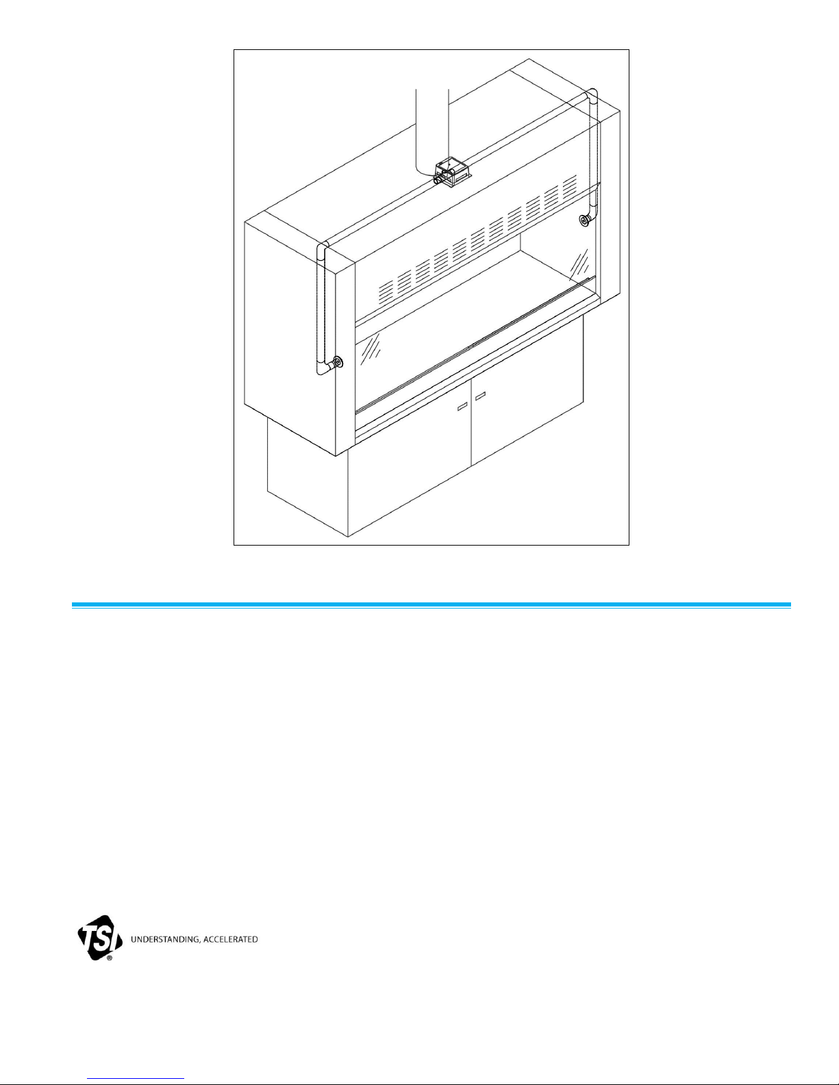
Step 1: Select location of SENSOR ASSEMBLY,
typically lying on top of the fume hood
(Figure 4). SENSOR ASSEMBLY must be
located to reference room air, within 15 ft of
the controller. If using an existing velocity
sensor, make sure to use O-ring to seal the
side-wall sensor to the sensor housing and
tighten down self-tapping nuts using the two
posts on the sensor housing.
Step 2: Determine MOUNTING FLANGE location. Use
Figure 2 as a guide.
Step 3: Drill 1½” hole through the fume hood liner at
this location
Figure 1: Parts
Page 2

Figure 2: Mounting Flange Location
Figure 3: Finished Assembly
Page 3
USA Tel: +1 800 874 2811
UK Tel: +44 149 4 459200
France Tel: +33 491 11 87 64
Germany Tel: +49 241 523030
India Tel: +91 80 67877200
China Tel: +86 10 8219 7688
Singapore Tel: +65 6595 6388
Figure 4: Typical Installation
Sen so r Assembly
If the Averaging Fume Hood Vent Kit is added to an existing fume hood controller, then the sensor assembly
must be assembled.
Step 1: Open the Sensor Assembly Box, and screw the Sensor in.
Step 2: Close the Sensor Assembly Box. Screw the box together, using the #4-40 screw provided.
This concludes the installation of the Fume Hood Sensor Venting Kit. If you have questions, please call TSI at
(651) 490-2811 or 1-800-874-2811.
TSI Incorporated – Visit our website www.tsi.com for more information.
P/N 1980334 Rev. F ©2014 TSI Incorporated Printed in U.S.A.
 Loading...