

Page 1
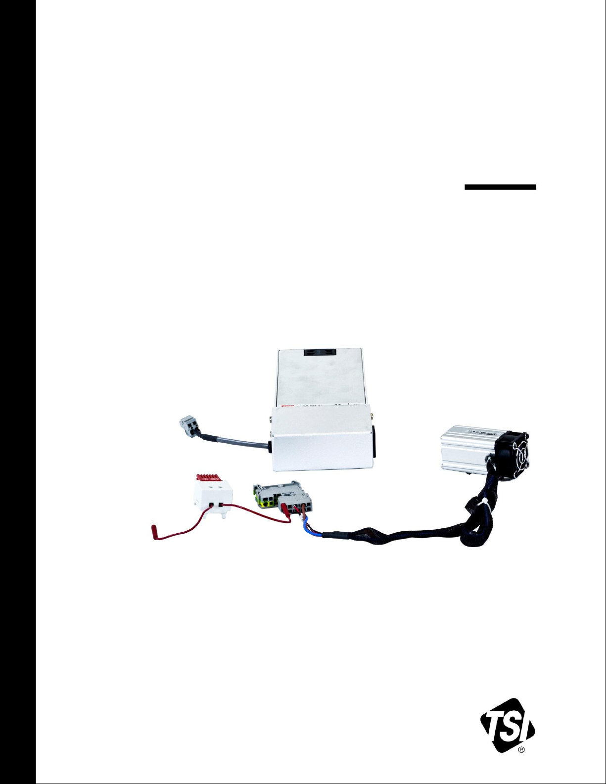
INSTALLING THE
ENCLOSURE HEATER
MODEL 854033
QUICK START GUIDE
P/N 6008412, REVISION B
JANUARY 2016
_______________
TSI and TSI logo are registered trademarks of TSI Incorporated.
Page 2
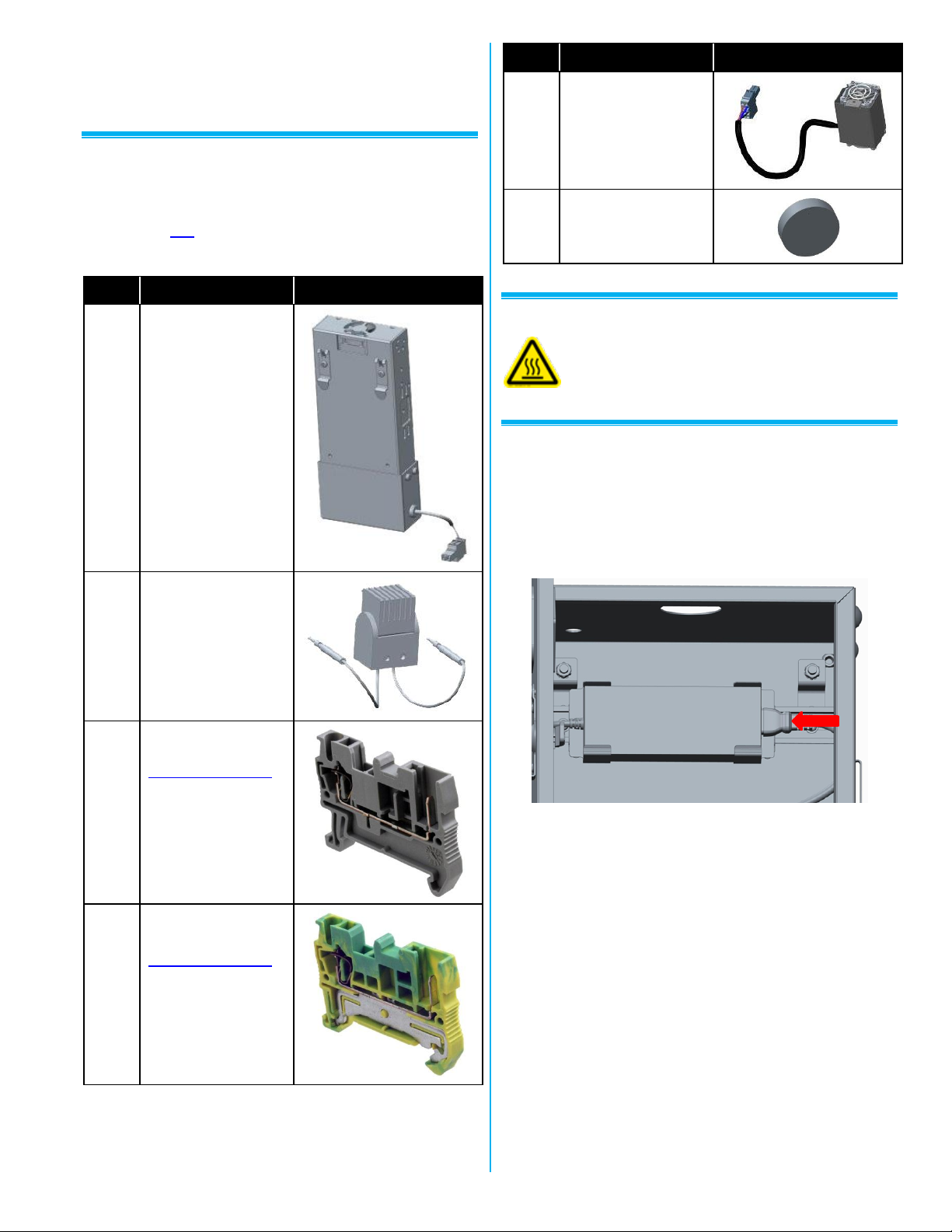
Qty.
Item Description
Reference Picture
1
Power Supply,
300 watts
1
Thermostat
1
Power Connector
www.phoenixcontact.com
Feed-through terminal
block. Gray. Small,
P/N 3040012.
1
Ground Connector
www.phoenixcontact.com
Spring cage ground
terminal block. Green
Small P/N 3040025
Qty.
Item Description
Reference Picture
1
Heater
2
Vent Plugs
Warns that the instrument could be hot to the
touch or a burn hazard.
This guide will help you quickly install the Enclosure
Heater (854033) for the Environmental Enclosure
(854030).
Unpacking
1. Unpack the enclosure heater and verify that all the
items listed in the following table are present.
2. Contact TSI immediately if items are missing or
broken.
Warning Labels
Installing the Enclosure Heater (854033)
1. If Model 854034 power supply is installed, unplug
the DC power cable from DIN rail, unplug the main
power to the power supply, and snap the power
supply clip off the upper DIN rail and go to step 3.
2. If not already installed, add top DIN Rail Mount:
Remove nuts from welded stud and mount DIN Rail
Mount to Weld Stud. Install the upper DIN Rail onto
the mounting brackets using the provided #10
hardware. Mount the DIN Rail w/Mounting Brackets
to the Enclosure Weld Studs using the Kep Nuts
provided with the enclosure.
-2-
Page 3
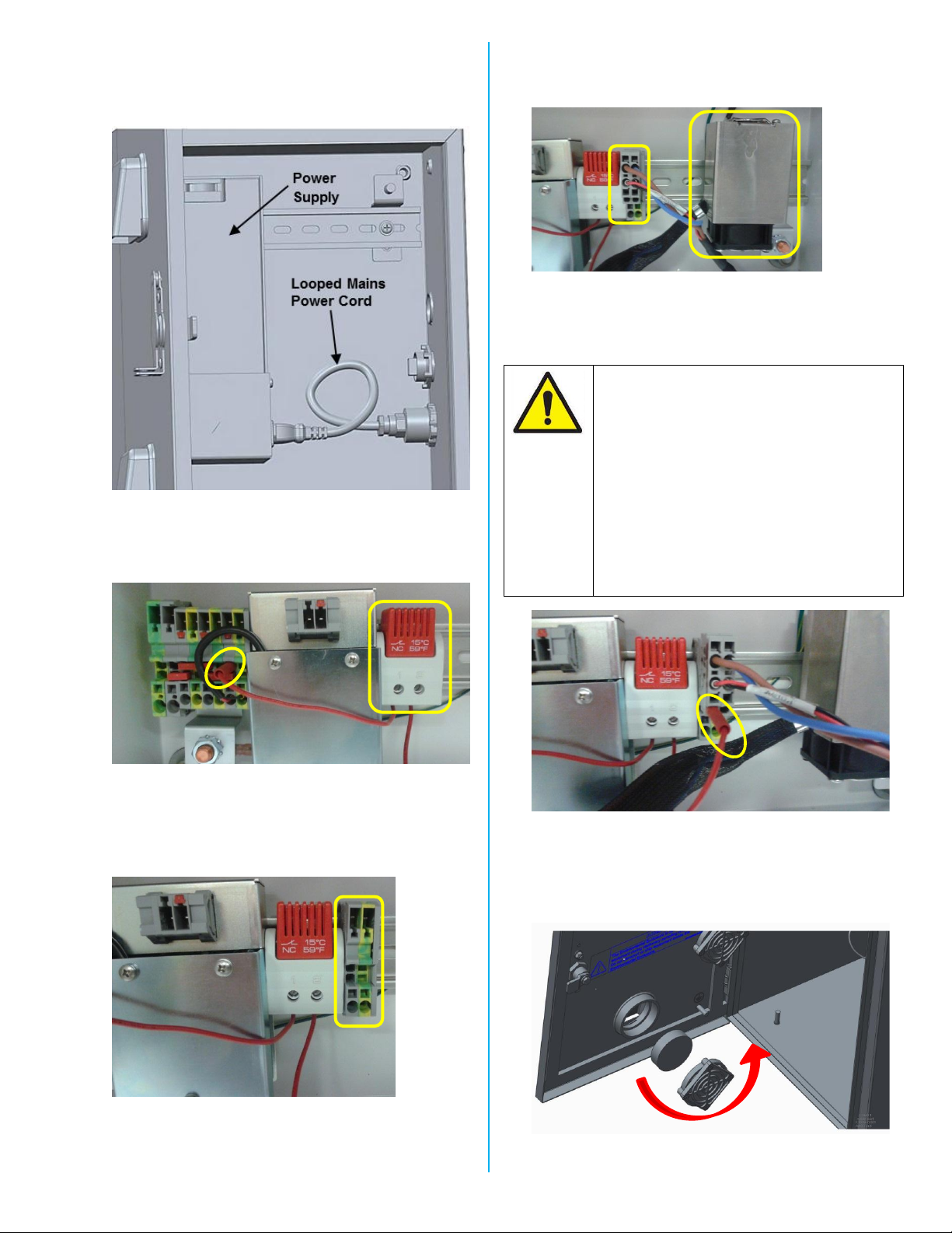
DO NOT PLUG THE THERMOSTAT
WIRES INTO THE GREEN/YELLOW
PHOENIX GROUND CONTACTS
THE THERMOSTAT MUST PROVIDE
POWER TO THE HEATER. BYPASSING
THE THERMOSTAT, OR PLUGGING
THE HEATER DIRECTLY INTO THE
POWER SIDE OF THE DIN RAIL, WILL
CAUSE THE HEATER TO RUN
CONSTANTLY AND MAY DAMAGE
EQUIPMENT AND LEAD TO
PREMATURE FAILURE(S).
3. Mount the Heater Power Supply onto the upper DIN
Rail by hanging the top bracket clips on the DIN Rail
and snapping the bottom back into place. Attach the
Mains Power Cord, looping the cord as shown.
6. Install the Heater onto the DIN Rail and Plug into the
two Phoenix Connectors just installed to the right of
the Thermostat.
7. Plug the remaining Thermostat wire into the ”+” side
of the Heater Connector (left side of connector,
Gray) as shown.
4. Install the thermostat onto the lower DIN Rail and
plug thermostat wire into the “+” (Gray) DIN Rail
Power Connector.
5. Install the Gray Power Connector and Green Ground
Connector onto the DIN Rail next to the Thermostat.
Ensure Power Connector (Gray) is to the left of the
Ground Connector and next to the Thermostat.
8. Insert vent plugs into openings to help keep heat
inside enclosure in cold environments. Twist covers
counter clockwise to remove. Hand-tighten after
inserting plug.
-3-
Page 4
USA Tel: +1 800 874 2811
UK Tel: +44 149 4 459200
France Tel: +33 1 41 19 21 99
Germany Tel: +49 241 523030
India Tel: +91 80 67877200
China Tel: +86 10 8219 7688
Singapore Tel: +65 6595 6388
Nominal Heater
Power ...............
24 Volts DC; 100 Watts
Temp Range ....
Will keep instruments inside
enclosure above 0°C (32°F) with
outside temperature down to -20°C
(-4°F).
9. Remove vent plugs when weather conditions do not
require use of the heater. Twist vent cover counter
clockwise to remove vent plugs. Hand-tighten after
removing plug.
Operating Instructions
1. The heater thermoset is preset, no adjustment or
setting is required. Thermostat will turn heater on
automatically when the temperature inside the
enclosure reaches approximately +5°C (41°F).
2. The thermostat will automatically turn off the heater
when the temperature in the enclosure is
approximately +15°C (59°F).
Specifications
TSI Incorporated – Visit our website www.tsi.com for more information.
P/N 6008412 Rev. B ©2016 TSI Incorporated Printed in U.S.A.
 Loading...