

Page 1
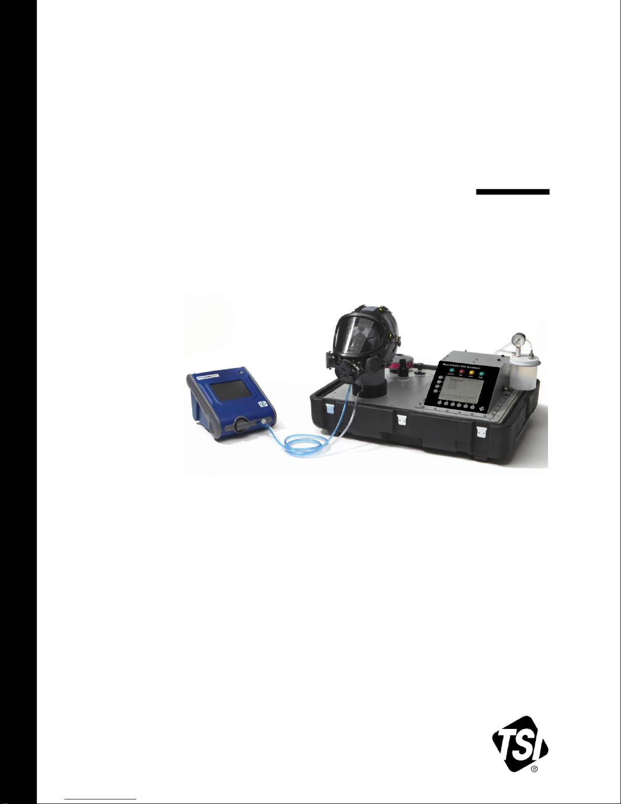
MASK INTEGRITY TEST
ACCESSORY (MITA)
MODEL 8120
QUICK START GUIDE
P/N 6006154, REVISION F
AUGUST 2015
Model 8120 Mask Integrity Tester is patented under
U.S. Patents No. 8,312,761 and 8,621,914. Additional patents are pending.
Page 2

Page 3
C A U T I O N
TWO PERSON LIFT RECOMMENDED
C A U T I O N
DO NOT ALLOW CONTAMINANTS TO FALL INTO ANY OF THE
HEADFORM BASE PORTS OR THE AEROSOL MIXER PORT
Safety and Precautions
This section provides instructions to ensure safe and proper handling of the
Mask Integrity Test Accessory (MITA).
Please read the entire operator’s manual
before operating this equipment.
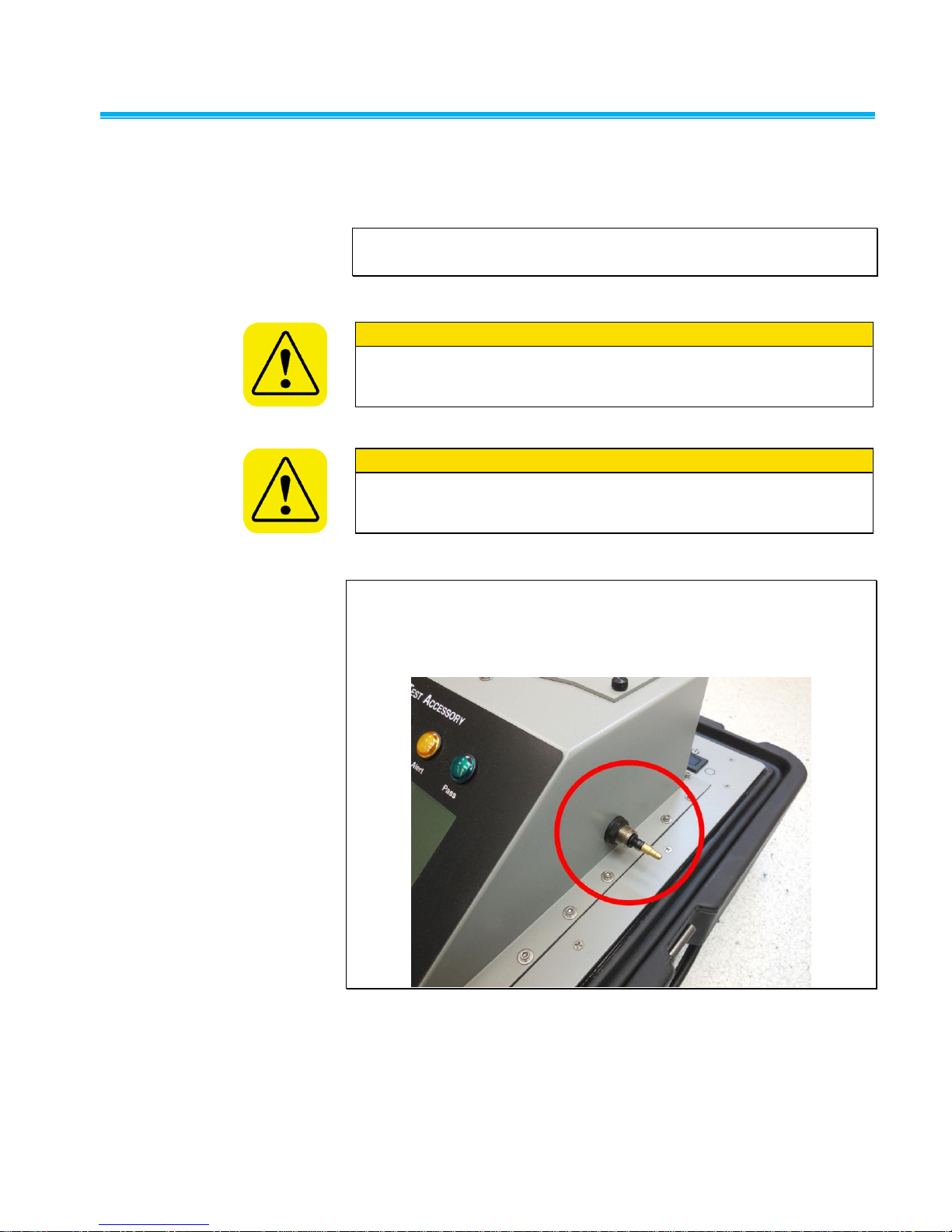
Do NOT remove or obstruct inlet located in the right hand
side of the CEU. There are no user adjustments
necessary for this inlet.
iii
Page 4

(This page intentionally left blank)
iv
Page 5

Contents
Safety and Precautions ............................................................................. iii
Introduction ................................................................................................. 1
Unpacking and System Components ....................................................... 2
System Components .............................................................................. 2
Unpacking Instructions ........................................................................... 3
Power-Up Instructions ............................................................................ 4
Getting to Know the MITA .......................................................................... 5
Setup Instructions .................................................................................. 6
Setup Cables and Hoses ....................................................................... 6
Setup Aerosol Generator ....................................................................... 8
Set up the PortaCount® Respirator Fit Tester ...................................... 10
Prepare Masks for Test ........................................................................ 12
MITA Communicator Software ................................................................ 13
Installation ............................................................................................ 13
v
Page 6

(This page intentionally left blank)
vi Mask Integrity Test Accessory (MITA) Model 8120
Page 7

Introduction
DT
Drink Tube
EV
Exhalation Valve
CEU
Control Electronics Unit
DP1
Differential Pressure Transducer #1
DP3
Differential Pressure Transducer #3
DP5
Differential Pressure Transducer #5
This Quick Start Guide is designed to expedite the basic setup and
powering up of the MITA. Upon completion of the following steps the MITA
will be ready to proceed with the Self Check or Test Masks functions. Refer
to the Operators Manual for additional and more detailed information.
The TSI Mask Integrity Test Accessory (MITA) works in tandem with the
PortaCount® Respirator Fit Tester to test for leaks or other defects in
CBRN gas masks and full-face respirators.
The MITA has been designed for ease-of-use and ease-of-transport. The
top half of the carrying case holds the instrument while the bottom half
forms the accessory compartment.
The display on the MITA guides the first time operator through step-by-step
prompts. The display also provides detailed guidance to how to use the
various accessories.
The following acronyms are used in the MITA menu structure and in this
Quick Start Guide.
1
Page 8
Unpacking and System Components
Note
Mask testing adapters and accessories are sold separately. Refer to
www.tsi.com for more information on the available MITA Mask
Adapter kits.
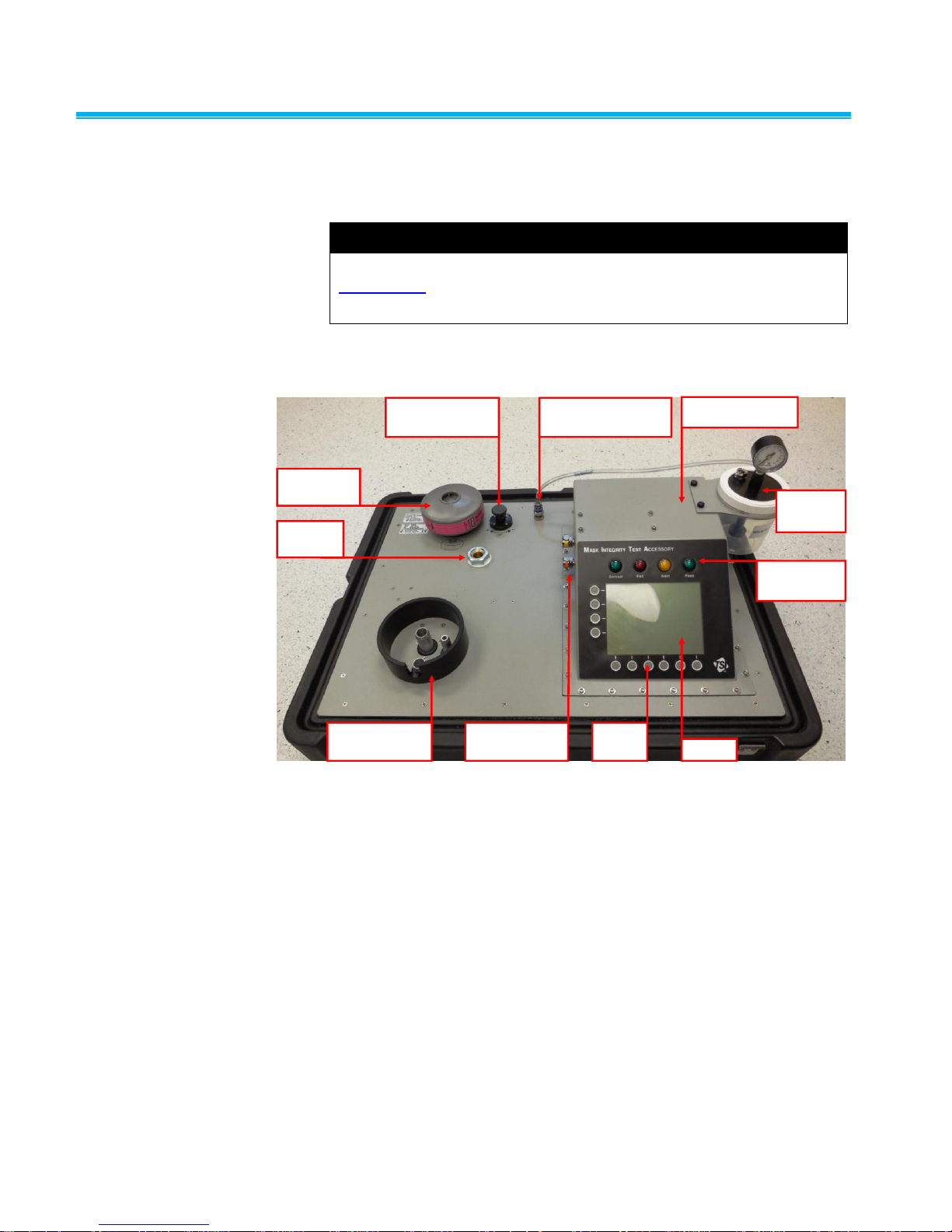
HEPA Filter
Cartridge
Pressure
Adjustment Valve
Aerosol Generator
Quick Connect Fitting
CEU
(Control Electronics Unit)
Mixer
Port
Headform
Mounting Base
DT & EV Quick
Connect Fittings
Keypad
Buttons
Display
Test Indicator
LEDs
Aerosol
Generator
Carefully unpack the Mask Integrity Test Accessory (MITA) from the
shipping container.
System Components
Front View of MITA Lid/Main Panel
2 Mask Integrity Test Accessory (MITA) Model 8120
Page 9
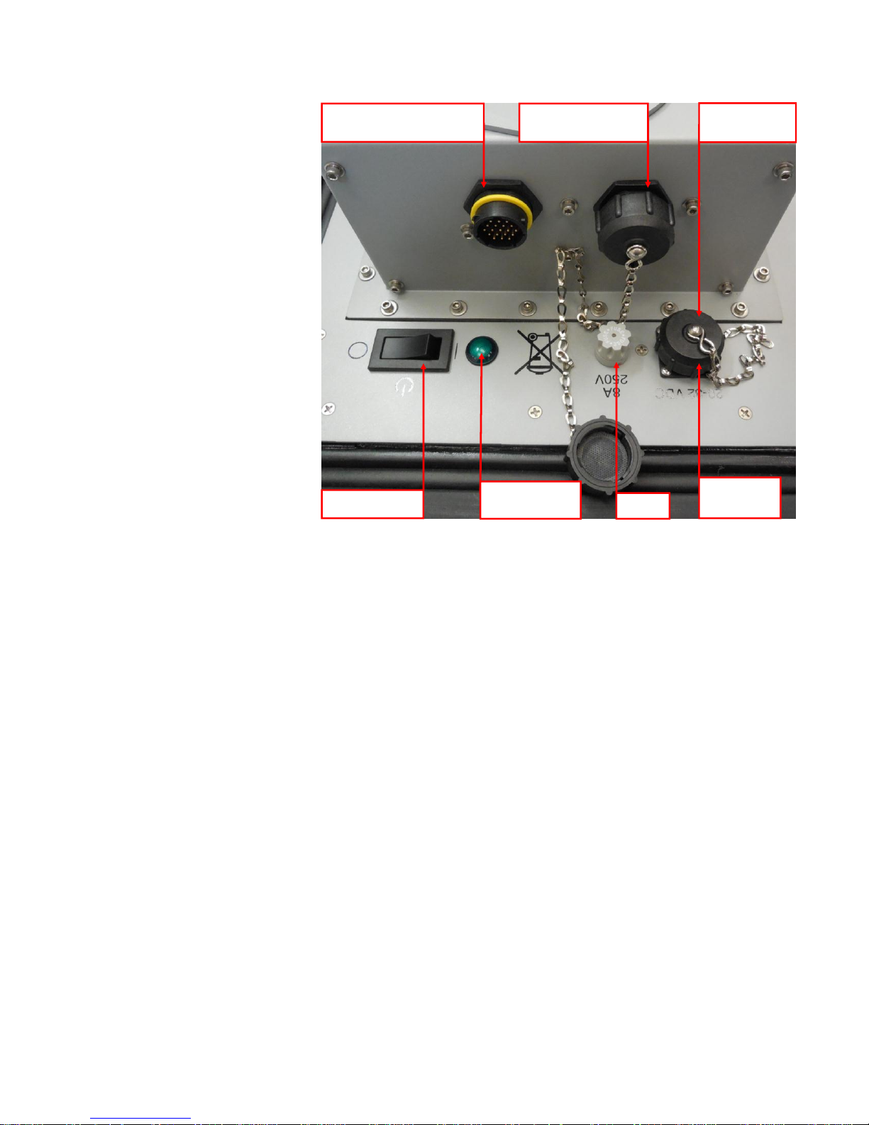
PortaCount Interface Cable
Connector (Yellow)
Computer Cable
Connector (Green)
Power Switch
Power Indicator
LED
Power Supply
Connector
Connector
Dust Cap
Fuse
Back View of CEU and Main Panel
Unpacking Instructions
1. Open latches on case.
2. Separate the lid/main-panel from the case and place lid/main-panel on
work surface (see “System Components and Standard Items” section
in the MITA Operator’s Manual to identify accessories).
3. Remove and Expand Hood by unfolding and pulling the white tab
outward.
4. Loosen wing-nut fasteners for accessories panel cover on the lower
half of the case and open panel.
5. Remove accessories from case.
6. Store lower half of case out of the way.
Quick Start Guide 3
Page 10
Power-Up Instructions
Note
If there is an ambient change in temperature greater than 20°F (6.6°C)
from the MITA’s storage location to operating location, wait at least one
hour before operating to allow the internal temperature of the MITA to
equalize.
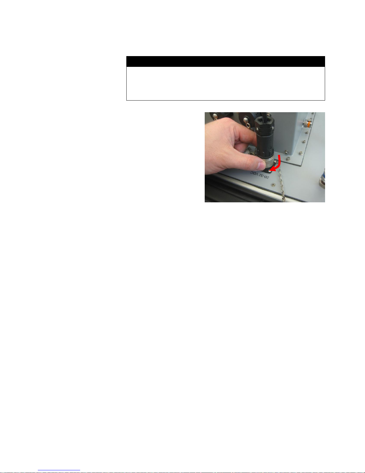
1. Connect Power Line
Cord to Power Supply.
2. Remove the Dust Cap
and connect Power
Supply to the 20 to
32 VDC Connector.
3. Twist knurled locking
ring clockwise until it
stops.
4. Plug Power Line Cord
to Power Source (100
to 240 VAC).
5. Turn Power Switch
On.
(continued on next page)
4 Mask Integrity Test Accessory (MITA) Model 8120
Page 11
Getting to Know the MITA
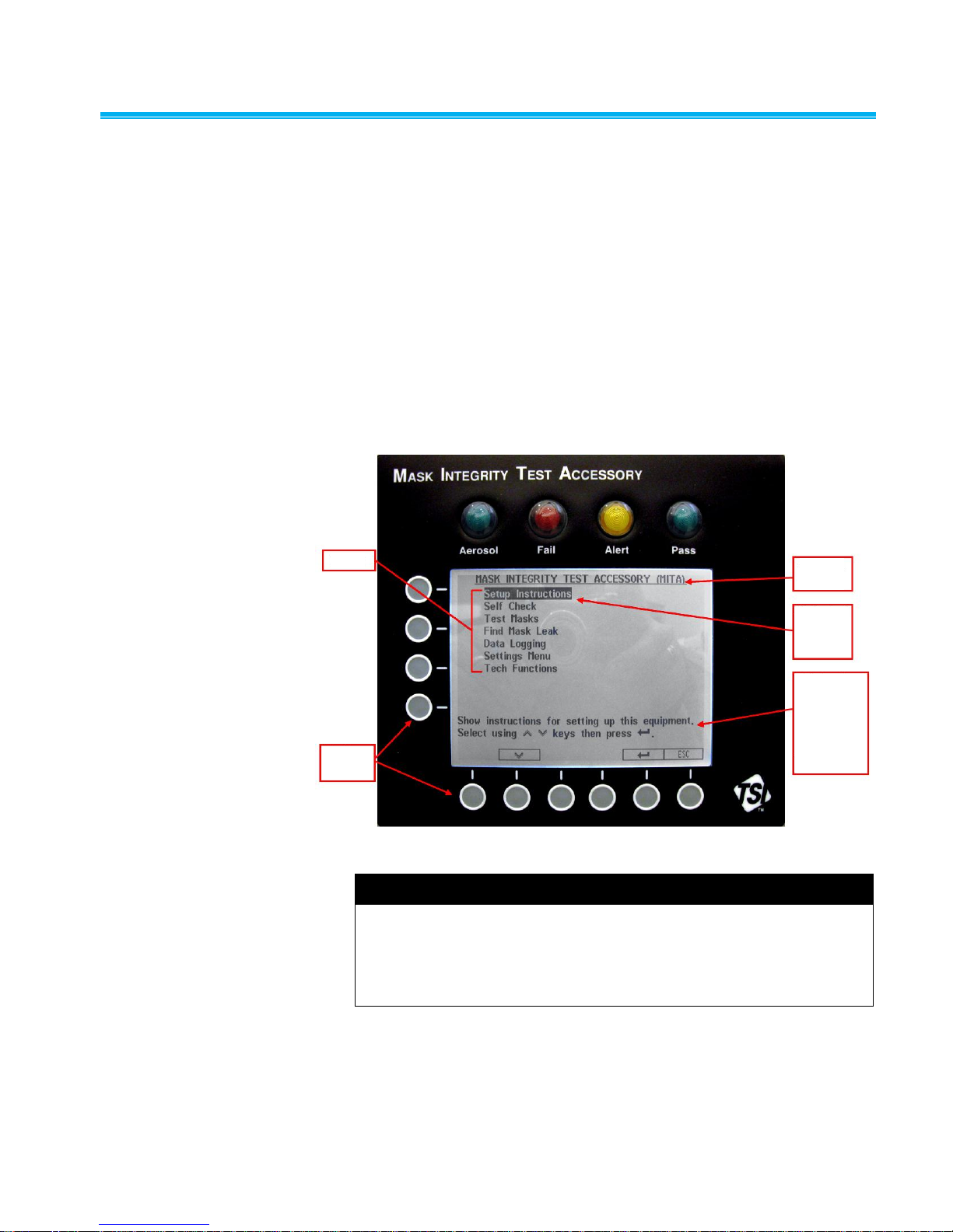
Menu
Softkey
Buttons
Screen
Title
Selected
Menu
Item
Objective
of the
Selected
Menu Item
and
Instructions
Note
All the LED’s will turn on and then off when the Main Menu is first
displayed. If there are any Errors, the Alert LED will remain on, and the
Errors will be displayed along with suggestions for resolving them. Press
or ESC to continue. Refer to the Troubleshooting section in the
Operator’s Manual if any errors are displayed.
The MITA is operated by selecting options from the displayed MENU using
the keypad on the Display Panel. The operator also needs to make
appropriate hardware configuration changes as prompted from the display
during the tests.
The objective of the selected option and instructions are described at the
bottom of each screen.
The row of six circles across the bottom of the display and four circles
across the side of the display are softkeys. The function of the softkeys,
where applicable, is displayed either immediately next to or above them. If
a key action is available, the key function is shown on the display inside a
rectangular box. Momentarily press the softkey button to select the
corresponding softkey option.
MITA Display Panel with Main Menu
Quick Start Guide 5
Page 12
Setup Instructions
Note
MITA includes the interface cable needed for the 8030/8038 models of
the PortaCount Respirator Fit Tester. The 8020/8020M interface cable
(P/N 801767) is sold separately.
The Setup Instructions guide the operator through setting up of the
equipment and the steps needed to prepare the MITA for the Self Check
and Mask Testing.
To continue with Setup Instructions, select Setup Instructions from the
main menu using the ▲▼ keys to and press . The following menu is
displayed:
The Setup Instructions menu includes the following tasks:
Setup Cables and Hoses
Setup Aerosol Generator
Setup the PortaCount® Respirator Fit Tester
Prepare Masks for Test
When each task has been performed, press ESC to return to the Setup
Instructions menu and then select the next available task.
When the tasks for the Setup Instructions are complete, press ESC again
to return to the main menu.
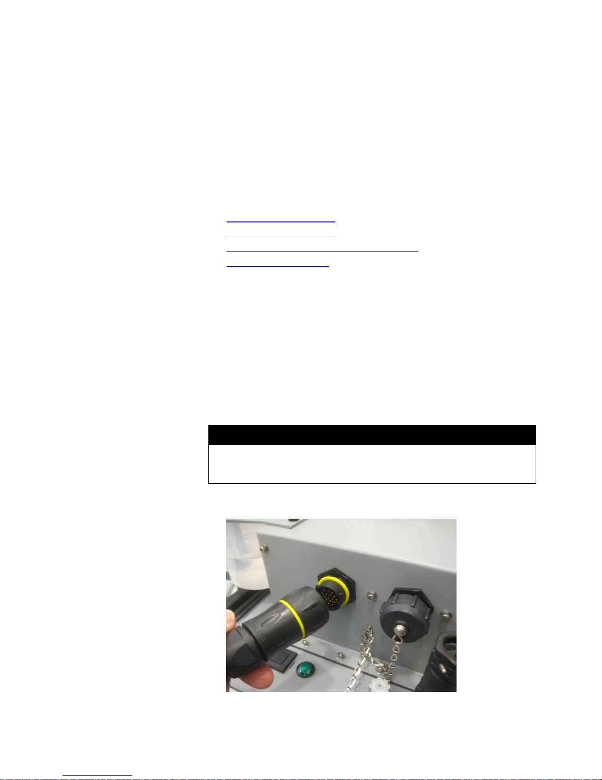
Setup Cables and Hoses
1. Remove dust cap from the connector with yellow ring, located on the
back right of MITA CEU.
2. Plug the yellow-ringed PortaCount Interface Cable to the connector
mentioned previously in step 1.
6 Mask Integrity Test Accessory (MITA) Model 8120
Page 13
Note
The EV Adapters discussed in step 3 are provided in the MITA Mask
Adapter Kits and are specific to the make and model of the respirator
being tested. During the Self Check, be sure to use the appropriate EV
Adapter according to the respirator being tested.
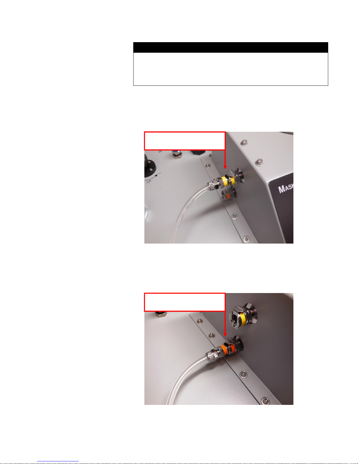
3. If applicable, plug the yellow Exhalation Valve (EV) Adapter sample
Exhalation Valve (EV) Adapter
Sample Hose and connection
Drink Tube (DT) Sample Hose
and connection
hose to the yellow EV connector.
Not all respirator models will require the use of an Exhalation Valve
Adapter, including most APR and SCBA respirators.
4. Plug the orange Drink Tube (DT) sample hose to the orange
DT connector.
Not all respirator models will require the use of a Drink Tube Adapter,
including most APR and SCBA respirators.
Quick Start Guide 7
Page 14
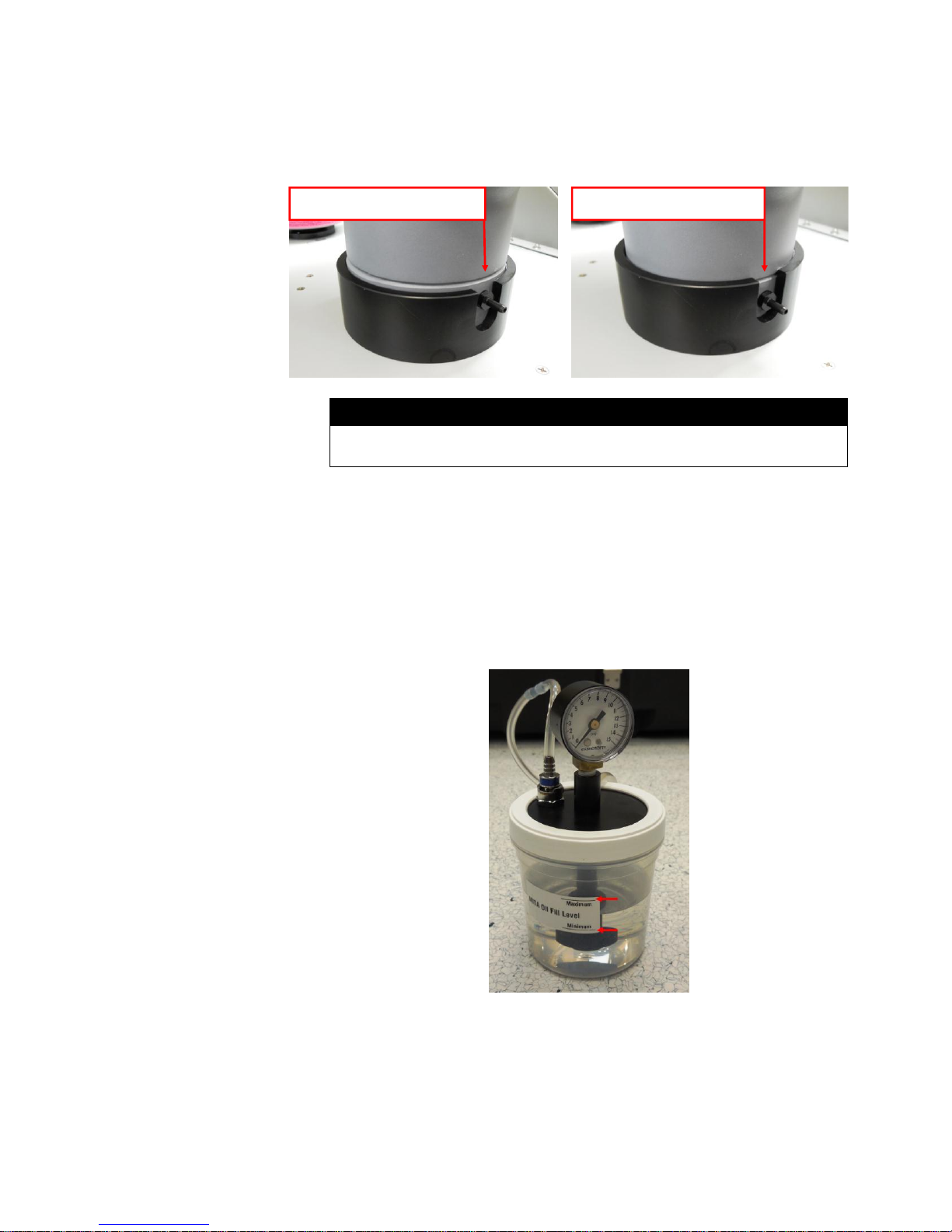
5. (If not already installed) Screw in the HEPA Filter cartridge.
Not Fully Seated Fully Seated
Note
The ring along the base of the Headform will be below the top of the
mounting base collar when the Headform is fully seated.
6. Install the Headform to the Headform Mounting Base and push
down tight.
Setup Aerosol Generator
1. Remove the Aerosol Generator reservoir and fill with Emery oil. Emery
oil should be within the indicated minimum and maximum lines on the
reservoir.
2. Reattach reservoir to Aerosol Generator assembly. Screw assembly on
tight, but do NOT over-tighten as this could cause the assembly to leak
particles.
3. Attach the Aerosol Generator Mounting Bracket to the MITA using the
thumbscrews.
4. Slide the Aerosol Generator into the mounting bracket.
8 Mask Integrity Test Accessory (MITA) Model 8120
Page 15
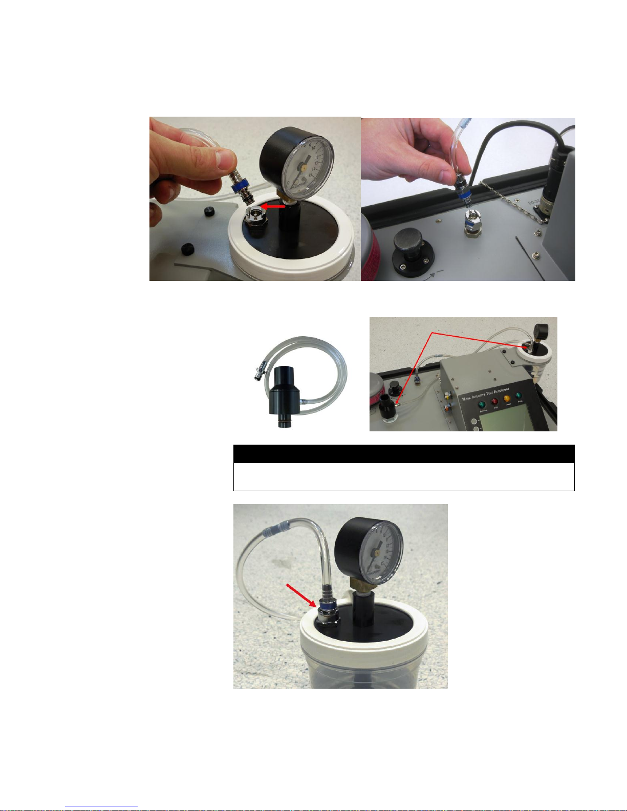
5. Remove the blue air supply hose from its storage location on the
Note
When storing the Aerosol Generator, it must be dry and empty of oil, and
the air supply hose must be plugged into the aerosol generator output.
Aerosol Generator and connect it to the blue Aerosol Generator quick
connect fitting located on the MITA main panel.
6. Install the Aerosol Mixer between the Aerosol Generator output and the
Aerosol Mixer Port.
Quick Start Guide 9
Page 16
Set up the PortaCount® Respirator Fit Tester
Note
The following examples pictured will use the 8030 and 8038 models of
the PortaCount Respirator Fit Tester.
If you are using the 8030 or 8038 model of PortaCount you must have
version 2.6 or greater firmware installed to communicate with the MITA.
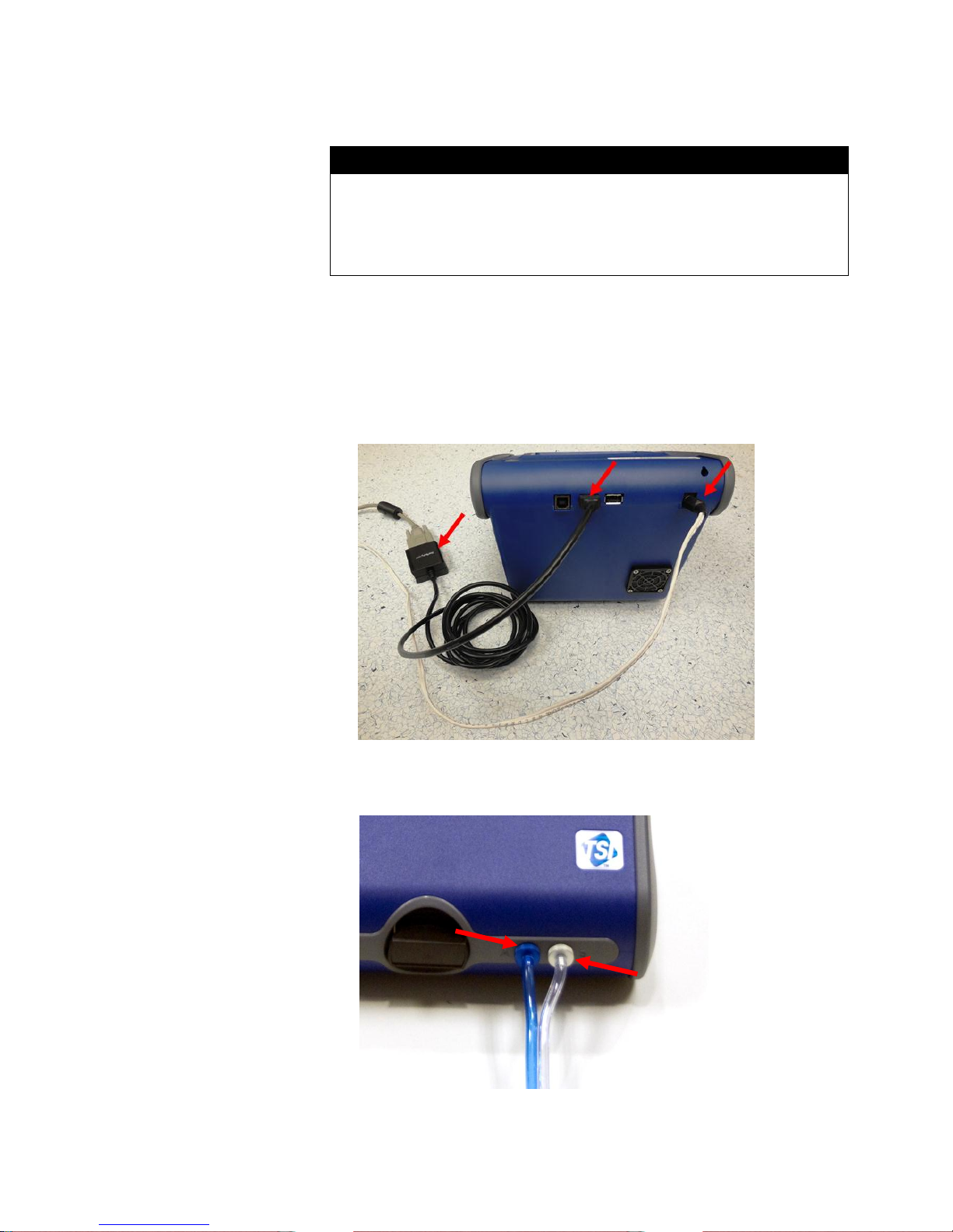
1. Connect the USB-to-Serial Converter to DB9 connection of PortaCount
interface cable.
2. Plug the USB end of the USB-to-Serial Converter to either type A USB
port located on back of PortaCount unit.
3. Connect the power supply barrel connector from the PortaCount
interface cable to the power supply connection on the back of
PortaCount unit.
4. Connect the end of the Twin Tube sample tubing provided with the
MITA, which is evenly cut to the color-coded fittings on the PortaCount
Fit Tester.
10 Mask Integrity Test Accessory (MITA) Model 8120
Page 17
5. Remove the Alcohol Cartridge from the Alcohol Fill Capsule and gently
Note
If operating the Model 8038 PortaCount Pro+ Respirator Fit Tester, do
NOT select the N95 checkbox when performing the Daily Checks.
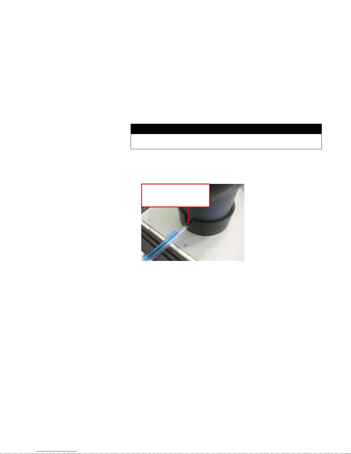
Clear Twin Tube sample
hose connected to Mask
Sample port
shake it to allow excess alcohol to drip back into the Capsule. Refer to
the PortaCount user’s manual for more information on how to properly
charge the alcohol cartridge prior to use.
6. Insert the Alcohol Cartridge into the cartridge cavity of the PortaCount
Respirator Fit Tester. It should slide in with little effort. DO NOT
FORCE IT. When almost fully inserted, firmly twist the Alcohol
Cartridge clockwise until it locks into position.
7. Perform a PortaCount Daily Check every day as described in the
PortaCount Fit Tester User’s Manual before using with MITA.
8. At the other end of the Twin Tube sample tubing, the clear hose is
approximately 1 inch longer than the blue hose. AFTER performing a
PortaCount daily check, connect the clear hose to the mask sample
port at the bottom of the Headform.
9. If using the 8030 or 8038 models of PortaCount, they must remain on
the “Activities” screen. Trying to use the 8030 or 8038 on any other
screen will cause intermittent “unexpected response” errors on MITA.
Quick Start Guide 11
Page 18

Prepare Masks for Test
Note
If you have not already performed a Self Check for the day, please
complete this process BEFORE testing a mask.
WAIT to install the Mask on the Headform until the Mask Protection
Factor test prompts to install it. The mask is installed ON the Headform
ONLY during the Mask Protection Factor test.
If the mask being tested has a Drink Tube or Exhalation Valve that will
be tested, leave the mask OFF the Headform. Both Drink Tube Test and
Exhalation Valve Test are done with the mask OFF the Headform.
Note
Typically masks seal better to the Headform bladder when placed
slightly higher up on the headform, so that the upper sealing surface is
less than an inch below the top of the headform bladder. This is not
applicable to all models and sizes of masks, and experience will help to
determine which masks fit best which way. Try adjusting the mask
higher or lower on the headform first when experiencing difficulties
passing a Protection Factor test.
This menu option provides information on how to prepare the gas masks
and full face respirators for testing. The Mask Test Protocol is selected and
defined in the Settings Menu.
1. Before starting, thoroughly inspect the mask to detect any obvious
defects.
2. If the inside of the mask is dirty or contaminated, it should be cleaned.
3. Remove the mask filter before conducting the Mask Protection Factor
test.
4. Install the appropriate Mask Filter Plug in place of the mask filter
removed in the previous step.
When installing the Mask to the Headform:
1. Loosen the mask straps completely so they will go around the back of
the Headform
2. Locate the chin cup of the mask on the chin portion of Headform first,
and pull the mask straps up and back over the Headform, making sure
to keep it snug to the Headform.
3. Make sure the Mask is centered on the Headform Bladder Seal.
4. Snug the straps tight.
5. Re-check to make sure the mask is centered from side to side.
12 Mask Integrity Test Accessory (MITA) Model 8120
Page 19

MITA Communicator Software
Note
The CD should automatically start running after about 30 seconds. If it
does not, select My Computer and view the root folder on the CD.
Double-click the file “autorun.exe.”
Installation
A personal computer running Windows
and 64-bit) operating system is required to install the MITA Communicator
software. Only an Administrator can install the MITA Communicator
software.
1. Insert the CD-ROM “MITA Communicator Software CD” into a
CD-ROM drive.
2. When the main installation screen appears, click on Install Software.
3. Either accept the default installation folder as displayed, or choose a
different preferred installation location. TSI recommends that you
accept the default location.
4. Select Next.
®
XP (32-bit), or Windows
®
7 (32-bit
5. Select I accept the terms of the License Agreement.
6. Select Next. A similar screen will appear with the TSI license
agreement, repeat this step.
7. Select Next. The next screen will display the progress of the MITA
Communicator installation.
8. Once the installation is complete, the “Installation Complete” window
will be displayed.
9. Select Finish.
10. Restart computer to finish installing MITA Communicator software.
Setup
1. Remove the dust cap on the Computer connector on the back of the
MITA. Install the green MITA computer cable.
2. Connect this cable to the 9-pin (male) COM (RS232) port on the
personal computer (PC). If the PC does not have a 9-pin serial
connector then use the USB to Serial converter to connect with a USB
port. Install the drivers for the converter following the instructions
located in Appendix C of the MITA Operator’s Manual.
®
Windows is a registered trademark of Microsoft Corporation.
Quick Start Guide 13
Page 20

3. Turn the MITA on. Select and open the Tech Functions Menu. The
password required to access this menu is “TSI”. Enter the password
then press SAVE & EXIT.
Configure Tech Functions menu as follows:
If USB to Serial converter is not used, set UART0 CTS Enable to
ENABLE.
If USB to Serial converter is used, set UART0 CTS Enable to
DISABLE.
4. Ensure the UART0 Baud Rate on the MITA Tech Functions screen
matches that shown in the MITA Communicator Software Setup tab.
The factory default for both settings is 115200. For slower PCs the
Baud rate may need to be lowered in both locations to ensure data
records are transmitted properly.
5. Determine the COM Port number assigned by the PC to the USB-toSerial connection. Locate Ports (COM & LPT) in Device Manager. To
access Device Manager for Windows® XP operating system, go to
Start menu and right-click on My Computer to access System
Properties. On the Hardware tab of the System Properties window
select Device Manager. To access Device Manager for Windows® 7
operating system, go to Start | Control Panel | Device Manager.
6. Right-click on the COM port associated with the USB-to-Serial
converter and make sure Flow Control is set to Hardware.
7.
Locate the MITA icon on your Windows® desktop or select Programs
from the Start menu then go to MITA Communicator and select MITA.
Informational window on MITA Communicator asks to select “UPLOAD
MASK PROTOCOLS” screen on MITA and enter the password. The
password for “UPLOAD MASK PROTOCOLS” screen on MITA is
“MITACOM”. Select OK to proceed.
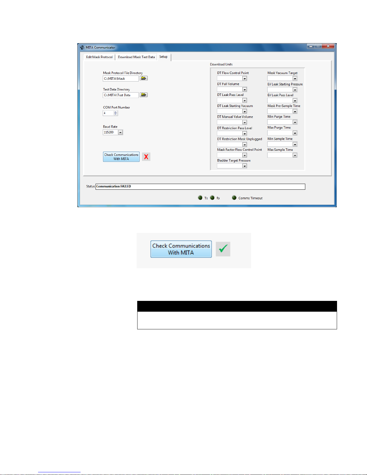
8. Go to the Setup tab and verify the COM Port number.
14 Mask Integrity Test Accessory (MITA) Model 8120
Page 21
Note
For more information on Installation of the StarTech FTDI Drivers refer
to Appendix C in the MITA Operator’s Manual.
9. Press the Check Communications with MITA button to initiate
communication. A green check should appear momentarily.
10. Exit MITA Tech Functions and proceed with the Settings Menu options
described in the Software Operation section of the MITA Operator’s
Manual.
Quick Start Guide 15
Page 22

Page 23

TSI Incorporated – Visit our website www.tsi.com for more information.
USA Tel: +1 800 874 2811
UK Tel: +44 149 4 459200
France Tel: +33 1 41 19 21 99
Germany Tel: +49 241 523030
India Tel: +91 80 67877200
China Tel: +86 10 8219 7688
Singapore Tel: +65 6595 6388
P/N 6006154 Rev. D ©2015 TSI Incorporated Printed in U.S.A.
 Loading...