


Model 3772
Model 3771
(discontinued)
CONDENSATION
PARTICLE COUNTER
MODEL 3772/3771
OPERATION AND SERVICE MANUAL
P/N 1980529, REVISION F
APRIL 2015


CONDENSATION
PARTICLE COUNTER
MODEL 3772/3771
OPERATION AND SERVICE MANUAL
Product Overview
1
Unpacking and
Setting Up the CPC
2
Instrument
Description
3
Instrument Operation
4
Technical
Description
5
Particle Counting
6
Computer Interface
and Commands
7
Maintenance and
Service
8
Appendixes

Manual History
The following is a history of the Model 3772/3771 Condensation Particle
Counter Operation and Service Manual (Part Number 1980529).
Revision Date
A February 2006
B April 2006
C April 2007
D December 2009
E July 2011
F April 2015
iv

Warranty
Part Number
1980529 / Revision F / April 2015
Copyright
©TSI Incorporated / 2006–2015 / All rights reserved.
Address
TSI Incorporated / 500 Cardigan Road / Shoreview, MN 55126 / USA
Fax No.
651-490-3824
E-mail Address
particle@tsi.com
Limitation of Warranty
and Liability
(effective February 2015)
Seller warrants the goods, excluding software, sold hereunder, under normal use and service
as described in the operator's manual, to be free from defects in workmanship and material for
12 months, or if less, the length of time specified in the operator's manual, from the date of
shipment to the customer. This warranty period is inclusive of any statutory warranty. This limited
warranty is subject to the following exclusions and exceptions:
a. Hot-wire or hot-film sensors used with research anemometers, and certain other components
when indicated in specifications, are warranted for 90 days from the date of shipment;
b. Pumps are warranted for hours of operation as set forth in product or operator’s manuals;
c. Parts repaired or replaced as a result of repair services are warranted to be free from defects
in workmanship and material, under normal use, for 90 days from the date of shipment;
d. Seller does not provide any warranty on finished goods manufactured by others or on any
fuses, batteries or other consumable materials. Only the original manufacturer's warranty
applies;
e. This warranty does not cover calibration requirements, and seller warrants only that the
instrument or product is properly calibrated at the time of its manufacture. Instruments
returned for calibration are not covered by this warranty;
f. This warranty is VOID if the instrument is opened by anyone other than a factory authorized
service center with the one exception where requirements set forth in the manual allow an
operator to replace consumables or perform recommended cleaning;
g. This warranty is VOID if the product has been misused, neglected, subjected to accidental
or intentional damage, or is not properly installed, maintained, or cleaned according to the
requirements of the manual. Unless specifically authorized in a separate writing by Seller,
Seller makes no warranty with respect to, and shall have no liability in connection with, goods
which are incorporated into other products or equipment, or which are modified by any person
other than Seller.
The foregoing is IN LIEU OF all other warranties and is subject to the LIMITATIONS stated
herein. NO OTHER EXPRESS OR IMPLIED WARRANTY OF FITNESS FOR PARTICULAR
PURPOSE OR MERCHANTABILITY IS MADE. WITH RESPECT TO SELLER’S BREACH OF
THE IMPLIED WARRANTY AGAINST INFRINGEMENT, SAID WARRANTY IS LIMITED TO
CLAIMS OF DIRECT INFRINGEMENT AND EXCLUDES CLAIMS OF CONTRIBUTORY OR
INDUCED INFRINGEMENTS. BUYER’S EXCLUSIVE REMEDY SHALL BE THE RETURN OF
THE PURCHASE PRICE DISCOUNTED FOR REASONABLE WEAR AND TEAR OR AT
SELLER’S OPTION REPLACEMENT OF THE GOODS WITH NON-INFRINGING GOODS.
TO THE EXTENT PERMITTED BY LAW, THE EXCLUSIVE REMEDY OF THE USER OR
BUYER, AND THE LIMIT OF SELLER'S LIABILITY FOR ANY AND ALL LOSSES, INJURIES,
OR DAMAGES CONCERNING THE GOODS (INCLUDING CLAIMS BASED ON CONTRACT,
NEGLIGENCE, TORT, STRICT LIABILITY OR OTHERWISE) SHALL BE THE RETURN OF
GOODS TO SELLER AND THE REFUND OF THE PURCHASE PRICE, OR, AT THE OPTION
OF SELLER, THE REPAIR OR REPLACEMENT OF THE GOODS. IN THE CASE OF
SOFTWARE, SELLER WILL REPAIR OR REPLACE DEFECTIVE SOFTWARE OR IF UNABLE
TO DO SO, WILL REFUND THE PURCHASE PRICE OF THE SOFTWARE. IN NO EVENT
SHALL SELLER BE LIABLE FOR LOST PROFITS, BUSINESS INTERRUPTION, OR ANY
SPECIAL, INDIRECT, CONSEQUENTIAL OR INCIDENTAL DAMAGES. SELLER SHALL
NOT BE RESPONSIBLE FOR INSTALLATION, DISMANTLING OR REINSTALLATION
COSTS OR CHARGES. No Action, regardless of form, may be brought against Seller more than
12 months after a cause of action has accrued. The goods returned under warranty to Seller's
factory shall be at Buyer's risk of loss, and will be returned, if at all, at Seller's risk of loss.
Buyer and all users are deemed to have accepted this LIMITATION OF WARRANTY AND
LIABILITY, which contains the complete and exclusive limited warranty of Seller. This
LIMITATION OF WARRANTY AND LIABILITY may not be amended, modified or its terms
waived, except by writing signed by an Officer of Seller.
v

Service Policy
Knowing that inoperative or defective instruments are as detrimental to TSI as they are to our
customers, our service policy is designed to give prompt attention to any problems. If any mal-
function is discovered, please contact your nearest sales office or representative, or call TSI’s
Customer Service department at 1-800-874-2811 (USA) or (651) 490-2811.
Trademarks
Scanning Mobility Particle Sizer and SMPS are trademarks of TSI Incorporated.
Aerosol Instrument Manager is a registered trademark of TSI Incorporated.
Microsoft and Windows are registered trademarks of Microsoft Corporation.
vi Model 3772/3771 Condensation Particle Counter

Laser Safety
W A R N I N G
The use of controls, adjustments, or procedures other than those
specified in this manual may result in exposure to hazardous optical
radiation.
Safety
This section provides instructions to ensure safe and proper operation and
handling of the Model 3772/3771 Condensation Particle Counter (CPC).
There are no user-serviceable parts inside the instrument. Refer all repair
and maintenance to a qualified technician. All maintenance and repair
information in this manual is included for use by a qualified technician.
The Model 3772/3771 CPC is a Class I laser-based instrument. During
normal operation, you will not be exposed to laser radiation. However, you
must take certain precautions or you may expose yourself to hazardous
radiation in the form of intense, focused visible light. Exposure to this light
can cause blindness.
Take these precautions:
Do not remove any parts from the CPC unless you are specifically told
to do so in this manual.
Do not remove the CPC housings or covers while power is supplied to
the instrument.
Chemical Safety
The Model 3772/3771 CPC uses n-butyl alcohol (butanol) as a working
fluid. Butanol is flammable. Butanol is also toxic if inhaled. Refer to a
Material Safety Data Sheet for butanol and take these precautions:
Use butanol only in a well-ventilated area. Under normal operating
conditions butanol is exhausted into the air at approximately 0.015 g
per minute.
Butanol vapor is identified by its characteristically strong odor and can
easily be detected. If you smell butanol and develop a headache, or
feel faint or nauseous, leave the area at once. Ventilate the area before
returning.
vii

C a u t i o n
Butanol is flammable. Butanol is also potentially toxic if inhaled. Use
butanol only in a well-ventilated area. If you smell butanol and develop a
headache, or feel faint or nauseous, leave the area at once. Ventilate the
area before returning.
W A R N I N G
Although the CPC is appropriate for monitoring inert process gases such
as nitrogen or argon, it should not be used with hazardous gases such
as hydrogen or oxygen. Using the CPC with hazardous gases may
cause injury to personnel and damage to equipment.
C a u t i o n
Caution means be careful. It means if you do not follow the procedures
prescribed in this manual you may do something that might result in
equipment damage, or you might have to take something apart and start
over again. It also indicates that important information about the operation
and maintenance of this instrument is included.
W A R N I N G
Warning means that unsafe use of the instrument could result in serious
injury to you or cause irrevocable damage to the instrument. Follow the
procedures prescribed in this manual to use the instrument safely.
Description of Safety L a bels
This section acquaints you with the advisory and identification labels on the
instrument and used in this manual to reinforce the safety features built into
the design of the instrument.
Caution
Warning
viii Model 3772/3771 Condensation Particle Counter

Caution or Warning Symbols
Warns you that uninsulated voltage within the instrument may
have sufficient magnitude to cause electric shock. Therefore,
it is dangerous to make any contact with any part inside the
instrument.
Warns you that the instrument contains a laser and that
important information about its safe operation and
maintenance is included. Therefore, you should read the
manual carefully to avoid any exposure to hazardous laser
radiation.
Warns you that the instrument is susceptible to electro-static
dissipation (ESD) and ESD protection procedures should be
followed to avoid damage.
Indicates the connector is connected to earth ground and
cabinet ground.
1. Serial Number label –
displayed on the back panel
2. Laser Radiation label –
located internally on the optics
housing
3. Electrical shock caution
label – displayed on back
panel
4. Laser device compliance
label – displayed on back
panel
The following symbols may accompany cautions and warnings to indicate
the nature and consequences of hazards:
Labels
Advisory labels and identification labels are attached to the outside of the
CPC housing and to the optics on the inside of the instrument. Labels for
the Model 3772/3771 CPC are described below:
Safety ix

5. Caution label
6. European Recycling Label –
displayed on the back panel
(indicates item is nondisposable and must be
recycled).
7. French language electrical
safety and laser compliance
labels – displayed on the back
panel
8. NRTL TÜV SÜD Mark –
displayed on the back panel.
This mark identifies the
product as meeting safety
regulations in the US, Canada
and Europe and further
identifies the product as one
for which ongoing production is
monitored for quality.
9. TSI Address and Service
Label – displayed on the back
panel
10. Saturator Wick Removal
caution label – displayed on
the bottom of the enclosure
x Model 3772/3771 Condensation Particle Counter

Contents
Manual History ........................................................................................... iv
Warranty ...................................................................................................... v
Safety ......................................................................................................... vii
Laser Safety ......................................................................................... vii
Chemical Safety ................................................................................... vii
Description of Safety Labels ................................................................ viii
Caution .............................................................................................. viii
Warning ............................................................................................. viii
Caution or Warning Symbols ............................................................. ix
Labels .................................................................................................... ix
About This Manual ................................................................................. xvii
Purpose ............................................................................................... xvii
Organization ........................................................................................ xvii
Related Product Literature ................................................................. xviii
Submitting Comments ......................................................................... xix
CHAPTER 1 Product Overview .............................................................. 1-1
Product Description ............................................................................. 1-1
How it Works ....................................................................................... 1-2
CHAPTER 2 Unpacking and Setting up the CPC ................................. 2-1
Packing List ......................................................................................... 2-1
Unpacking ........................................................................................... 2-2
Setting Up ........................................................................................... 2-3
Remove Protective Caps ................................................................. 2-3
Mounting the Bracket and Fill Bottle ................................................ 2-3
Filling the Fill Bottle with Butanol ..................................................... 2-4
Connecting the Butanol Drain Bottle ............................................... 2-4
Apply Power to the CPC .................................................................. 2-4
Supply External Vacuum to the CPC ............................................... 2-5
Positioning the CPC ......................................................................... 2-5
CHAPTER 3 Instrument Description ...................................................... 3-1
Model 3772 Front Panel ...................................................................... 3-1
LCD Display and Keypad ................................................................. 3-1
Aerosol Inlet ..................................................................................... 3-2
Status Light ...................................................................................... 3-2
Particle Light .................................................................................... 3-2
Flash Memory Card Slot .................................................................. 3-2
Model 3771 Front Panel ...................................................................... 3-3
Model 3772/3771 Back Panel ............................................................. 3-3
AC Connector and Switch ................................................................ 3-3
USB Communication Port ................................................................ 3-3
RS-232 Serial Connections ............................................................. 3-4
Analog Inputs ................................................................................... 3-5
DMA/Analog Output and Pulse Output ............................................ 3-5
Ethernet Communication Port.......................................................... 3-6
xi

Butanol Fill Port ............................................................................... 3-6
External Vacuum Port ...................................................................... 3-6
Drain Port ........................................................................................ 3-7
Instrument Cooling Fan ................................................................... 3-7
Cover .................................................................................................. 3-7
Bottom Panel ...................................................................................... 3-7
Internal Instrument Components ........................................................ 3-8
Water Removal Pump ..................................................................... 3-8
Filters ............................................................................................... 3-9
Valves .............................................................................................. 3-9
Pressure Transducers ..................................................................... 3-9
Electronics Boards ........................................................................... 3-9
Basic Instrument Functions .............................................................. 3-10
Concentration Measurement ......................................................... 3-10
Total Count Mode (3772 only) ....................................................... 3-11
Water Removal .............................................................................. 3-11
Internal Data Logging (3772 only) ................................................. 3-11
Remote Access of Instrument ....................................................... 3-11
External Vacuum Pump or Source ................................................ 3-11
Flow Rate Control .......................................................................... 3-12
Temperature Control ..................................................................... 3-12
Inlet Pressure Measurement ......................................................... 3-12
CHAPTER 4 Instrument Operation ........................................................ 4-1
Operating Precautions ........................................................................ 4-1
Power Switch ...................................................................................... 4-1
Warm-up ............................................................................................. 4-1
Status Indicator ................................................................................... 4-2
Particle Indicator ................................................................................. 4-2
Communication ................................................................................... 4-2
Model 3772 LCD Display and Keypad ............................................ 4-3
Model 3772 Keypad Navigation ...................................................... 4-3
Concentration ..................................................................................... 4-4
Total Count Mode (3772 only) ............................................................ 4-5
User Settings ...................................................................................... 4-5
Data Logging (3772 only) ................................................................ 4-6
Water Removal ................................................................................ 4-6
Totalizer Time (3772 only) ............................................................... 4-7
Auto Fill ............................................................................................ 4-7
Analog Out ....................................................................................... 4-7
Data Averaging (3772 only) ............................................................. 4-8
Drain ................................................................................................ 4-8
Status .................................................................................................. 4-8
Saturator Temp (Temperature) ....................................................... 4-9
Condenser Temp (Temperature) ..................................................... 4-9
Optics Temp (Temperature) ............................................................ 4-9
Cabinet Temp (Temperature) .......................................................... 4-9
Ambient Pressure ............................................................................ 4-9
Orifice Pressure ............................................................................. 4-10
Nozzle Pressure ............................................................................ 4-10
Laser Current ................................................................................. 4-10
Liquid Level ................................................................................... 4-10
Analog Inputs ................................................................................. 4-10
Flash Status (3772 only) ............................................................... 4-10
xii Model 3772/3771 Condensation Particle Counter

USB Status .................................................................................... 4-10
Firmware Version ........................................................................... 4-11
Using the Flash Memory Card (3772 only) ....................................... 4-11
Aerosol Instrument Manager® Software ............................................ 4-13
Moving and Shipping the CPC .......................................................... 4-13
CHAPTER 5 Technical Description ........................................................ 5-1
Theory ................................................................................................. 5-1
History ................................................................................................. 5-2
Adiabatic Expansion CNC ............................................................... 5-2
Two-Flow Mixing CNC ..................................................................... 5-3
Diffusional Thermal CNC ................................................................. 5-3
Design of the CPC .............................................................................. 5-5
Sensor .............................................................................................. 5-5
Critical Flow ..................................................................................... 5-7
Counting Efficiency and Response Time of the 3772/3771 CPC ....... 5-8
CHAPTER 6 Particle Counting ............................................................... 6-1
Optical Detection ................................................................................. 6-1
Total Count Accuracy .......................................................................... 6-2
Live-Time Counting ............................................................................. 6-2
Coincidence Correction for Pulse Output ........................................ 6-3
Particle Size Selector .......................................................................... 6-4
CHAPTER 7 Computer Interface and Commands ................................ 7-1
Computer Interface ............................................................................. 7-1
USB .................................................................................................. 7-1
Ethernet ........................................................................................... 7-1
Flash Memory Card Specification (3772 only) ................................. 7-5
RS-232 Serial Communications ...................................................... 7-6
Commands .......................................................................................... 7-7
CHAPTER 8 Maintenance and Service .................................................. 8-1
Replacement Parts Kits ...................................................................... 8-2
Draining Butanol from the Butanol Reservoir ..................................... 8-4
Changing the Filters ............................................................................ 8-5
Butanol Fill and Drain Filters ............................................................ 8-5
Micro Pump Filter ............................................................................. 8-6
Removing and Installing the Saturator Wick ....................................... 8-7
Verifying Flow Rate ........................................................................... 8-10
Calibration ......................................................................................... 8-10
Correcting Flooded Optics ................................................................ 8-11
Viewing Analog Pulses ..................................................................... 8-12
Calibration Reminder ........................................................................ 8-14
False Count Check ........................................................................... 8-14
Error Messages and Troubleshooting ............................................... 8-15
Technical Contacts ........................................................................... 8-17
Returning the CPC for Service .......................................................... 8-18
APPENDIX A Specifications .................................................................. A-1
APPENDIX B Firmware Commands ...................................................... B-1
READ Commands .............................................................................. B-1
SET Commands ................................................................................. B-5
MISC (MISCELLANEOUS) Commands ............................................ B-8
HELP Commands .............................................................................. B-9
Contents xiii

Figures
APPENDIX C References ....................................................................... C-1
Index
Reader’s Comments Sheet
1-1 Model 3772 Condensation Particle Counter ..................................... 1-2
1-2 Model 3771 Condensation Particle Counter ..................................... 1-2
2-1 View of Fill Bottle Bracket Mounting ................................................. 2-3
3-1 View of the Model 3772 Front Panel ................................................. 3-1
3-2 View of the Model 3771 Front Panel ................................................. 3-3
3-3 Back Panel of the Model 3772/3771 CPC ........................................ 3-4
3-4 Sample Digital Pulse from Pulse Output Port at the Back Panel
of the CPC ........................................................................................ 3-6
3-5 Bottom Panel Showing Removable Saturator Base ......................... 3-7
3-6 Internal Components of the Model 3772/3771 CPC ......................... 3-8
3-7 Electronics Boards inside the Model 3772/3771 CPC .................... 3-10
4-1 Model 3772 Display During Warm-Up .............................................. 4-2
4-2 Model 3772 Display After Warm-Up is Completed ........................... 4-2
4-3 Model 3772 Front Panel LCD Display and Keypad .......................... 4-3
4-4 Total Count Mode Data Screen ........................................................ 4-5
4-5 Initial Total Mode Data Screen .......................................................... 4-5
4-6 User Settings Display ........................................................................ 4-5
4-7 Status Display ................................................................................... 4-9
4-8 Status Parameter Display for Diagnostics ........................................ 4-9
4-9 Reformatting the Flash Memory Card ............................................. 4-12
5-1 Flow Schematic of the Model 3772/3771 CPC ................................. 5-6
5-2 Counting Efficiency Curve of 3772/3771 CPC .................................. 5-8
5-3 Response Time of 3772/3771 CPC ................................................ 5-10
7-1 Digi Device Discovery Screen ........................................................... 7-2
7-2 Configure Network Settings Screen .................................................. 7-3
7-3 Digi Connect ME Configuration and Management Screen ............... 7-3
7-4 Main Screen HTML Page .................................................................. 7-4
7-5 RS-232 Connector Pin Designations ................................................ 7-6
8-1 Vacuum Drain Cap Assembly ........................................................... 8-4
8-2 Replacing the Butanol Fill and Drain Filters ...................................... 8-5
8-3 Replacing the Micro Pump Filter ....................................................... 8-6
8-4 Inlet Tube .......................................................................................... 8-7
8-7 O-Rings on Saturator Base (P/N 2501172 and 2501569) ................ 8-9
8-8 O-Rings on Saturator Base (P/N 2500021) ...................................... 8-9
8-9 Connecting SMC Plug to Detector Board ....................................... 8-13
8-10 Typical Analog Pulse Trace ............................................................ 8-13
xiv Model 3772/3771 Condensation Particle Counter

Tables
2-1 Model 3772 CPC Packing List .......................................................... 2-1
2-2 Model 3771 CPC Packing List .......................................................... 2-2
6-1 Coincidence Levels Based on 0.35 µsec Pulse Width ...................... 6-3
7-1 Signal Connections for RS-232 Configurations ................................ 7-7
8-1 3772/3771 CPC Maintenance and Replacement Kits ....................... 8-2
8-2 Troubleshooting ............................................................................... 8-15
A-1 Model 3772/3771 CPC Specifications ............................................. A-2
Contents xv

(This page intentionally left blank)
xvi Model 3772/3771 Condensation Particle Counter

Purpose
Organization
About This Manual
This is an operation and service manual for the Model 3772/3771
Condensation Particle Counter (CPC).
The following is a guide to the organization of this manual:
Chapter 1: Product Overview
This chapter gives an introduction to the Model 3772/3771
Condensation Particle Counter, a list of features, and a brief
description of how the instrument works.
Chapter 2: Unpacking and Setting Up the CPC
This chapter gives a packing list and the step-by-step procedure for
getting the CPC ready to operate.
Chapter 3: Instrument Description
This chapter describes features and controls that run the CPC,
including the components on the front-panel, back-panel, bottompanel, cover and inside the instrument. It also covers the basic
functions of the instrument.
Chapter 4: Instrument Operation
This chapter describes the operation of the instruments.
Chapter 5: Technical Description
This chapter details the principle of operation, theory, and performance
of the condensation nucleus counter.
Chapter 6: Particle Counting
This chapter describes the particle counting modes.
Chapter 7: Computer Interface and Commands
This chapter describes the computer interface hardware, associated
firmware commands, and flash memory card.
Chapter 8: Maintenance and Service
This chapter describes the recommended practices and schedule for
routine cleaning, checking and calibration.
Appendix A: Specifications
This appendix lists the specifications of the Model 3772/3771
Condensation Particle Counter.
xvii

Appendix B: Firmware Commands
This appendix lists all the serial commands for communications
between the CPC and the computer.
Appendix C: References
This chapter lists all of the references that have been used within the
text of the manual. In addition, a general list of references pertaining to
condensation nucleus counters is included.
Related Product Lite r ature
Model 3007 Condensation Particle Counter Operation and Service
Manual (part number 1930035) TSI Incorporated
Model 3775 Condensation Particle Counter Operation and Service
Manual (part number 1980527) TSI Incorporated
Model 3776 Ultrafine Condensation Particle Counter Operation
and Service Manual (part number 1980522) TSI Incorporated
Model 3783 EPC™ Environmental Particle Counter™ Monitor
Operation and Service Manual (part number 6003653) TSI
Incorporated
Model 3785 Water-based Condensation Particle Counter
Operation and Service Manual (part number 1933001) TSI
Incorporated
Model 3786 Ultrafine Water-based Condensation Particle Counter
Operation and Service Manual (part number 1930072) TSI
Incorporated
Model 3787 General Purpose Water-based Condensation Particle
Counter Operation and Service Manual (part number 6003712) TSI
Incorporated
Model 3788 Nano Water-based Condensation Particle Counter
Operation and Service Manual (part number 6003713) TSI
Incorporated
Model 376060 Particle Size Selector Instruction Manual (part
number 1930013) TSI Incorporated
This manual contains operating instructions for the Model 376060
Particle Size Selector, an accessory for the Model 3772, 3771, and
3781 CPCs. The Model 376060 is a separating device that removes
small particles from an aerosol while passing larger particles.
Aerosol Instrument Manager® Software for CPC and EAD
Instruction Manual (part number 1930062) TSI Incorporated
This manual contains operating instructions for Aerosol Instrument
Manager Software for CPC and EAD, a software program that
monitors, calculates, and displays particle concentration data collected
by a CPC or an EAD.
xviii Model 3772/3771 Condensation Particle Counter

Submitting Comments
TSI values your comments and suggestions on this manual. Please use
the comment sheet on the last page of this manual to send us your opinion
on the manual’s usability, to suggest specific improvements, or to report
any technical errors.
If the comment sheet has already been used, please mail your comments
on another sheet of paper to:
TSI Incorporated
Particle Instruments
500 Cardigan Road
Shoreview, MN 55126
Fax: (651) 490-3824
E-mail Address: particle@tsi.com
About This Manual xix

(This page intentionally left blank)
xx Model 3772/3771 Condensation Particle Counter

C H A P T E R 1
Product Overview
This chapter contains an introduction to the Model 3772/3771
Condensation Particle Counter (CPC) and provides a brief explanation of
how the instrument operates.
Product Description
The Model 3772/3771 Condensation Particle Counter is a compact,
rugged, and full-featured instrument that detects airborne particles down to
10 nanometers in diameter at an aerosol flow rate of 1.0 liter per minute,
over a concentration range from 0 to 104 particles per cubic centimeter.
These CPCs are ideally suited for applications that do not require
measurement of high concentrations, such as basic aerosol research, filter
and air-cleaner testing, particle counter calibration, environmental
monitoring, mobile aerosol studies, particle shedding and component
testing, and atmospheric and climate studies. The Model 3772 CPC is also
compatible with TSI Scanning Mobility Particle SizerTM (SMPSTM)
spectrometers for particle size distribution measurements.
The successor to the Model 3010, 3760A, and 3762 CPCs, the Model 3772
and 3771 CPCs offer many new features and improvements:
Fast response to rapid changes in aerosol concentration (T
seconds)
Butanol-friendly features, including anti-spill design, water-removal
system, and improved resistance to optics flooding
Removable saturator wick for easy transport and maintenance
USB and Ethernet available
Auto recovery from power failure
The Model 3772 CPC offers the following additional features:
Built-in SMPS
Particle concentration, total counts, instrument status or user settings
shown on enhanced front panel LCD display
Built-in data logging and storage capability with removable memory
card
TM
spectrometer compatibility
95
3
1-1

Figure 1-1 Figure 1-2
Model 3772 Condensation Particle Counter Model 3771 Condensation Particle Counter
(discontinued)
How it Works
In the Model 3772/3771 Condensation Particle Counter (CPC), an aerosol
sample is drawn continuously through a heated saturator in which butanol
is vaporized and diffuses into the sample stream. Together, the aerosol
sample and butanol vapor pass into a cooled condenser where the butanol
vapor becomes supersaturated and ready to condense. Particles present in
the sample stream serve as condensation nuclei. Once condensation
begins, particles that are larger than a threshold diameter quickly grow into
larger droplets and pass through an optical detector where they are
counted easily.
The Model 3772/3771 CPC detects particles as small as 10 nanometer in
diameter and employs single-particle-count-mode operation to measure
concentrations up to 104 particles per cubic centimeter. The detector
counts individual pulses produced as each particle (droplet) passes
through the sensing zone. A high signal-to-noise ratio and continuous, livetime coincidence correction provide great measurement accuracy, even at
very low concentrations. An external vacuum pump is required to draw the
1-2 Model 3772/3771 Condensation Particle Counter

aerosol sample into the CPC. The 1.0 L/min aerosol flow rate is controlled
accurately and reliably using an internal critical orifice.
The CPCs use a laser-diode light source and diode photodetector to collect
scattered light from particles. An internal microprocessor is used for
instrument control and data processing.
Model 3772 CPC has a two-line LCD display which presents real-time
number concentration, totalizer function, and enables easy-to-use menus
for control operation functions and presents instrument status information
and user settings. A variety of communication options for computer data
acquisition are available. The 3772 CPC also includes on-board data
logging and storage using a removable flash memory card. Model 3771
has no display and no memory card.
Product Overview 1-3

(This page intentionally left blank)
1-4 Model 3772/3771 Condensation Particle Counter

Packing List
Qty.
Description
Model/
Part Number
1
Model 3772 CPC and Operation Manual
1980529
1
Power cable
(based on
destination)
1
Aerosol Instrument Manager® Software
390065
1
Fill Bottle
1035590
1
Drain Bottle
1035591
1
Bottle Bracket
1503475
1
Vacuum Drain Bottle Cap
1031526
1
RS-232 Cable (A-pin M/F, 12 ft)
962002
1
USB I/O Cable A/B 6 ft
1303740
1
SanDisk ImageMate 5-in-1 Card Reader
1500208
1
Data Memory Card
1500108
1
Saturator Wick CPC 3772
1600047
2
Water Removal Filter Inline, 25 micron 116" barb
1500192
3
Butanol Fill/Drain Filter Inline, 73 micron 18" barb
1602088
2
Saturator Base O-Ring FVMQ 1-010
2500021
1
Saturator Base O-Ring FVMQ 1-030
2501172
2
Saturator Base O-Ring EPDM 1-027
2501569
1
Krytox
®
O-ring Grease
1701154
1
Checkout Data Sheet
N/A 1 Certificate of Conformance
N/A
C H A P T E R 2
Unpacking and Setting
up the CPC
Use the information in this chapter to unpack the Model 3772/3771
Condensation Particle Counter (CPC) and set it up.
Tables 2-1 and 2-2 show the components shipped with the Model 3772
and 3771 CPCs.
Table 2-1
Model 3772 CPC Packing List
Krytox® is a registered trademark of DuPont.
2-1

Table 2-2
Qty.
Description
Model/
Part Number
1
Model 3771 CPC and Operation Manual
1980529
1
Power cable
(based on
destination)
1
Aerosol Instrument Manager® Software
390065
1
Fill Bottle
1035590
1
Drain Bottle
1035591
1
Bottle Bracket
1503475
1
Vacuum Drain Bottle Cap
1031526
1
RS-232 Cable (A-pin M/F, 12 ft)
962002
1
USB I/O Cable A/B 6 ft
1303740
1
Saturator Wick CPC 3771
1600047
2
Water Removal Filter Inline, 25 micron 116" barb
1500192
3
Butanol Fill/Drain Filter Inline, 73 micron 18" barb
1602088
2
Saturator Base O-Ring FVMQ 1-010
2500021
1
Saturator Base O-Ring FVMQ 1-030
2501172
2
Saturator Base O-Ring EPDM 1-027
2501569
1
Krytox® O-ring Grease
1701154
1
Checkout Data Sheet
N/A 1 Certificate of Conformance
N/A
Model 3771 CPC Packing List
Unpacking
Note: Some items in the lists above and those for future maintenance are
available for purchase as kits from TSI. A complete list of
replacement part kits is included in the maintenance section in
Chapter 8.
The Model 3772/3771 CPC comes fully assembled with protective
coverings on the inlet sample port, exit ports, and analog connectors. The
CPC comes packaged with the accessory kit. Use the packing list
(Table 2-1 or Table 2-2) to make certain that there are no missing
components.
The CPC box contains special foam cutouts designed to protect the
instrument during shipment. Save the original packaging materials for
future use should you need to ship the instrument or return the instrument
to TSI for service. Also keep the protective coverings for ports for shipping.
To avoid contaminating the instrument or the environment the CPC is
monitoring, do not remove the protective covers until you are ready to
install the instrument.
If anything is missing or appears to be damaged, contact your TSI
representative or contact TSI Customer Service at 1-800-874-2811 (USA)
or (651) 490-2811. Chapter 8, “Maintenance and Service,” gives
instructions for returning the CPC to TSI Incorporated.
2-2 Model 3772/3771 Condensation Particle Counter

Setting Up
This section contains instructions for setting up the Model 3772/3771 CPC.
Follow the instructions in the order given.
Remove Protective Caps
Remove all protective caps from the inlet sample port and exit flow ports at
the back of the instrument, also remove covers from the BNC connectors.
Mounting the Bracket and Fill Bottle
Mount the black anodized aluminum Bottle Bracket to the back panel using
two 8-32 38-inch screws and two no. 8 lock-washers found in the
mounting hole locations. Refer to the location of the bottle bracket shown in
Figure 2-1.
Find the Fill Bottle in the accessory kit. Connect the bottle tube fitting to the
Butanol Fill port at the back panel of the instrument. Position the bottle with
the fitting oriented for minimal stress on the tubing connector on the back
panel and place the bottle in the bracket. Both mated fittings are leak-tight
when disconnected.
Figure 2-1
View of Fill Bottle Bracket Mounting
Unpacking and Setting Up the CPC 2-3

Filling the Fill Bottle with Butanol
C a u t i o n
Butanol is flammable. Butanol is also potentially toxic if inhaled. Use
butanol only in a well-ventilated area. If you smell butanol and
develop a headache, or feel faint or nauseous, leave the area at
once. Ventilate the area before returning.
The Model 3772/3771 CPC uses reagent-grade n-butyl alcohol (butanol)
as the working fluid for particle growth. Pour the butanol into the Fill Bottle
to at least one-third full. Because of the leak-tight fittings and internal
solenoid valve, liquid will not flow into the CPC until the connections are
made, the instrument is switched on, and warm-up cycle is complete.
Note: Due to shipping regulations on flammable materials, n-butyl alcohol
(butanol) is not supplied with the CPC. Butanol may be purchased
from scientific chemical supply houses. Reagent grade of butanol is
required.
Connecting the Butanol Drain Bottle
A drain bottle should be connected to the Liquid Drain port at the back
panel of the CPC. The drain bottle collects butanol drained from the CPC
prior to transport and holds condensed water and butanol removed from
the condenser when the water removal system is turned on (see note
below). Draining butanol is described in Chapter 8 “Maintenance and
Service”.
Note: The water removal system will not work without a drain bottle
connected to the drain port. Refer to Chapter 4 for more details on
water removal system.
Apply Power to the CPC
Plug the power cord into the receptacle on the back panel of the CPC and
then plug it into the AC power source. The instrument uses a universal
power supply that accepts a variety of input voltages identified below.
Power 100 – 240 VAC, 50/60 Hz, 200 W maximum
Note: Make certain the power cord is plugged into a grounded power
outlet. Position the CPC so the power connector and switch are
easily accessible in case an emergency disconnect is required.
Apply power to the CPC by turning on the switch next to the power cord on
the back panel.
The instrument begins a warm-up sequence which typically lasts ten
minutes at room temperature. On the 3772, a ten-minute countdown is
displayed on the front panel. Particle concentration will not be accurately
measured during warm-up. After warm-up completes, the fluid begins to fill
the internal butanol reservoir in the saturator.
2-4 Model 3772/3771 Condensation Particle Counter

Supply External Vacuum to the CPC
An external vacuum port is located in the lower right-hand corner of the
CPC back panel. An external vacuum must be connected to this port
before the CPC can count particles. Vacuum source, either a central
building vacuum or a stand-alone vacuum source (e.g., TSI Model 3032
Vacuum Pump), should provide at least 60 kPa (18 in. Hg) vacuum and
1.0 L/min critical flow at the inlet of each CPC. Details of vacuum
specifications are given in Chapter 5.
Positioning the CPC
Place the CPC on a level surface. Ensure the cooling fan on the back
panel of the CPC is exposed to ambient air.
Note: If the CPC has n-butyl alcohol (butanol) in the reservoir, be very
careful when moving the CPC. See “Moving and Shipping the CPC”
section for details.
Unpacking and Setting Up the CPC 2-5

(This page intentionally left blank)
2-6 Model 3772/3771 Condensation Particle Counter

C H A P T E R 3
Instrument Description
Use the information in this chapter to become familiar with the location and
function of controls, indicators, and connectors on the Model 3772 and
3771 Condensation Particle Counters (CPC).
Model 3772 Front Panel
The main components of the 3772 front panel include the two-line LCD
display, six-key push button keypad, flash memory card slot, aerosol inlet,
two LED indicator lights (particle and status). These are identified in Figure
3-1 and described below.
LCD Display and Keypad
The two-line backlit LCD provides continuous real-time display of sample
data and is used in conjunction with the keypad to display option menus,
instrument status information, and user settings. Refer to Chapter 4 for
details on how to make selections and change options on the menus.
Figure 3-1
View of the Model 3772 Front Panel
3-1

Aerosol Inlet
The aerosol inlet is located on the front panel. The inlet consists of a ¼”
OD tube suitable for use with common tube fittings. Permanent fittings with
metal locking ferrules should be avoided since this can deform the tube
when overtightened, leading to leaks.
Status Light
The status light indicates the working status of the CPC. It will light only
when the key performance parameters of the CPC fall within an acceptable
range. More information on the status light is provided in Chapter 4.
Particle Light
The particle light flashes each time a particle is detected. At high particle
counting levels (>10 counts per second) the light appears continuously on.
Flash Memory Card Slot
The Model 3772 CPC provides storage of particle concentration data using
a standard flash memory card. A flash memory card is included. Refer to
Using the Flash Memory Card in Chapter 4 for more on how to use the
Flash Memory Card. Technical information is also found in Chapter 7.
3-2 Model 3772/3771 Condensation Particle Counter

Model 3771 Front Pane l
The main components of the 3771 front panel include the aerosol inlet and
two LED indicator lights (particle and status). These are identified in
Figure 3-2 and operate the same as described above for the 3772.
Figure 3-2
View of the Model 3771 Front Panel
Model 3772/3771 Back Panel
As shown in Figure 3-3, the back panel of the 3772/3771 CPC has power
and data connections, analog input/output connections, external vacuum
port, butanol fill and drain ports, and cooling fan. The function of the ports
and connectors are clearly labeled.
AC Connector and Switch
Plug the supplied AC power cable into this receptacle. The instrument
power switch is integrated into this AC receptacle at the top.
USB Communication Port
The Model 3772/3771 CPC provides a USB port for use with the TSI
Aerosol Instrument Manager® software included with the instrument. When
USB communications are used with the software, the computer
automatically recognizes the CPC as a TSI instrument. Additional
information on USB communications is found in Chapter 7 and also in the
Aerosol Instrument Manager® software manual.
Instrument Description 3-3

Note: Up to three CPCs can be simultaneously connected to one
computer running Aerosol Instrument Manager® software with USB
connections.
Figure 3-3
Back Panel of the Model 3772/3771 CPC
RS-232 Serial Connections
The Model 3772/3771 CPC provides two standard A-pin RS-232 serial
ports that allow communication between a computer and the CPC. Serial
commands are sent to and from the computer to monitor instrument status
information, to retrieve and monitor data, and to provide a variety of control
functions such as turning the water removal system on and off (Serial 1
only). Aerosol Instrument Manager® software may be used with Serial 1 as
well as USB. Information on RS-232 communications can be found in
Chapter 7, “Computer Interfaces and Commands”.
3-4 Model 3772/3771 Condensation Particle Counter

Analog Inputs
The CPC can monitor the analog voltages from two external sources via
the analog input BNC connectors on the back panel, labeled Analog Input
1 and Analog Input 2. The input voltage range for these ports is 0 to 10
volts. On the 3772 the analog voltages can be displayed on the LCD
display and saved to the removable Flash Memory Card or a computer.
Voltages from external pressure, flow, or temperature transducers can be
correlated to particle concentration in real time.
Amplification must be supplied by the user to bring low voltage signals to
the appropriate 0 to 10 volt range for best resolution.
DMA/Analog Output and Pulse Output
The DMA/Analog Output port provides an analog 0–10 V signal linearly
proportional to particle concentration. This particle concentration is
corrected for coincidence and equals the concentration displayed on the
front panel of the CPC and the concentration saved to the Flash Memory
Card or computer. Refer to Chapter 4 for details. In addition, on the 3772
this port can be configured by the Aerosol Instrument Manager® software to
provide the ramped voltage signal needed when the 3772 CPC is used as
part of the Scanning Mobility Particle SizerTM (SMPSTM) spectrometer.
Although this port on the 3771 is also labeled DMA/Analog Output, the
DMA function is not available for the 3771.
Pulse Output port provides a 5-volt (50-ohm termination) digital pulse for
each particle detected. This enables you to use your own counting
electronics hardware or provides a particle trigger for special applications.
The width of the pulse depends on both the shape of the photodetector
pulse and the trigger-level of the pulse threshold. Typical (nominal) pulse
widths are 350 nanoseconds (see Figure 3-4) for the 3772/3771 CPC. To
provide accurate pulse counts, use a counter that is capable of counting
pulses with a width of 50 nanoseconds or less.
Particle concentrations calculated based on the particle counts from the
counting electronics hardware are not corrected for particle coincidence.
Thus, the concentration obtained this way might be slightly lower than the
displayed concentration when particle concentration is high. Refer to
Chapter 6 “Particle Counting” for coincidence correction for pulse output.
The Pulse Output is a way to get raw particle count information. This
information is also available through serial command. Using the SSTART,2
command, described in Appendix B, you can read raw, uncorrected,
particle counts. TSI recommends using the SSTART,2 command for raw
counts as then all the information is shipped which is used to calculate the
corrected concentration, and there are no issues with the counters ability to
accurately count the pulses.
Instrument Description 3-5

Figure 3-4
Sample Digital Pulse from Pulse Output Port at the Back Panel of the CPC
Ethernet Communication Port
Instrument status including particle concentration of the Model 3772/3771
CPC can be monitored remotely from a local area network or over the
internet using the Ethernet communication port. Ethernet communications
are described further in Chapter 7, “Computer Interfaces and Commands”.
Butanol Fill Port
Butanol is supplied from the butanol fill bottle to the instrument at the
Butanol Fill port quick connect fitting.
External Vacuum Port
By attaching an external vacuum to this port, critical flow is established
through the critical orifice described in Chapter 5. The flow through this port
contains butanol vapor so the external vacuum must be properly vented
away from work areas or use charcoal filter to absorb the butanol vapor.
Charcoal filters can be ordered through TSI (P/N 1031492 and P/N
1031493). See Chapter 8 “Maintenance and Service.”
3-6 Model 3772/3771 Condensation Particle Counter

Cover
The bottom portion of the
chassis provides access to the
saturator wick. As shown in
Figure 3-5, the saturator base,
which is attached to the wick,
is visible above the centrally
located 2.5-inch diameter hole
on the bottom panel. The base
and wick can be removed for
maintenance, as described in
Chapter 8.
Figure 3-5
Bottom Panel Showing Removable Saturator
Base
Drain Port
This port is used to drain the working fluid (butanol) from the 5 cm3 liquid
reservoir and is used when collecting water extracted using the Water
Removal system. See Chapters 3 and 4 for more on the water removal
feature.
Instrument Cooling Fan
This fan cools internal electronics and dissipates heat generated during
cooling of the condenser. The fan is provided with a guard and a
removable filter that should be cleaned of dust periodically.
The cover refers to the removable section of the chassis covering the top
and sides of the CPC. It is secured to the chassis with four screws on the
bottom and two on the top and it can be removed for access to the interior
of the Model 3772/3771 CPC. Refer to Chapter 8 for details.
Bottom Panel
Instrument Description 3-7

Internal Instrument C o m ponents
1. Sensor assembly
5. Critical orifice
2. Water removal pump
6. Pressure transducers
3. Butanol fill filter
7. Power supply
4. Fan
Internal components are described in this section and identified in
Figure 3-6 and Figure 3-7.
Figure 3-6
Internal Components of the Model 3772/3771 CPC
Water Removal Pump
The Model 3772/3771 CPC uses a micro-flow Water Removal Pump to
remove condensate from the condenser. The Water Removal Pump draws
condensed butanol and water from the condensate collection reservoir.
Water removal prevents contamination of the butanol during operation in a
high humidity environment. When activated, the pump runs continuously. A
drain bottle must be connected for water removal to occur. For information
on operating the water removal pump refer to Chapter 4, “User Settings.”
3-8 Model 3772/3771 Condensation Particle Counter

Filters
The CPCs use three liquid filters. One liquid filter is used to filter butanol
supplied from the fill bottle while a second filters the butanol drain line. The
third is used to filter the condensed water and butanol mixture before it
passes through the Water Removal Pump.
Valves
Solenoid fill and drain valves enable butanol to be added or removed from
the liquid reservoir. The fill valve is actuated when the Auto-Fill is turned
ON and the level sensor indicates a low butanol level in the liquid reservoir.
When the butanol fill bottle is connected, butanol flows into the reservoir
until the level sensor indicates a full state. On the 3772, the drain valve is
activated through the front panel or through serial command. On the 3771,
the drain valve is activated through serial command. Butanol is drained
prior to shipment or removal of the saturator wick. See “User Settings” in
Chapter 4 and “Maintenance and Service” in Chapter 8.
Pressure Transducers
The Model 3772/3771 CPC uses three pressure transducers for monitoring
instrument flows. The differential pressure across the Critical Orifice is
measured to verify that a critical pressure is maintained across the orifice.
Differential pressure across the nozzle is measured and verifies the nozzle
in the optics block is free from obstruction. The ambient pressure is also
measured. These pressure transducers are mounted to the main PC
board. On the 3772, pressure information is viewable via the front panel
display. On both 3772 and 3771 CPCs, pressure information is available
through serial commands.
Electronics Boards
Four electronics boards identified in Figure 3-7, are used in
Model 3772/3771 CPC. The boards include main PC board, laser board,
detector board, and communication connector board. The 3772 also
includes a fifth board—flash memory board.
Instrument Description 3-9

Figure 3-7
1. Main PC board
4. Communication connector board
2. Laser board
5. Flash memory board (3772 only)
3. Detector board
Electronics Boards inside the Model 3772/3771 CPC
Basic Instrument Fu n c tions
This section describes basic instrument functions.
Concentration Measurement
Particle concentration is presented as particles per cubic centimeter (p/cc).
For the 3772, the particle concentration is displayed on the front panel LCD
in numeric form. For both CPCs, data is collected using the Aerosol
Instrument Manager® software or other terminal program (such as
HyperTerminal). Particle concentration is determined from the count rate
(particles counted per tenth of a second) and the aerosol flow rate,
nominally 1000 cubic centimeters per minute (cm3/min). The concentration
is also live-time corrected for coincidence. Refer to Chapter 6 “Live-Time
Counting” for more information.
3-10 Model 3772/3771 Condensation Particle Counter

Total Count Mode (3772 only)
Total Count Mode (also called totalizer mode) counts number of particles in
a given time period. This mode is used to improve counting resolution at
very low particle concentrations. Time and number of counts are shown on
the front panel display of the 3772.
Water Removal
When the aerosol sample has a dew point above the condenser
temperature of 22°C, water vapor may condense on the walls of the
condenser and run back into the saturator, contaminating the butanol over
time. Unlike its predecessor, the Model 3010, 3760A, or 3762 CPC, the
Model 3772/3771 CPC is able to capture condensed water vapor and
remove it, significantly reducing butanol contamination in high humidity
environment. The water removal process increases the butanol
consumption. For additional information refer to Chapter 4.
Internal Data Logging (3772 only)
A removable Flash Memory Card can be inserted in the slot on the 3772
front panel to store data including particle concentration and analog input
data. Data can then be transferred to a computer for further data
processing. Refer to Chapter 4 for more details. It is not recommended you
use a Flash Memory Card and Aerosol Instrument Manager® software or
terminal program to collect data simultaneously to avoid data transfer
interference.
Remote Access of Instrument
The Model 3772/3771 CPC provides an Ethernet port to connect the
instrument to a network for monitoring status information. Status
information includes saturator, condenser, optics temperatures, laser
power, and particle concentration, etc. The data is updated once every five
seconds. Refer to Chapter 7 for more details.
External Vacuum Pump or Source
The external vacuum pump or source must provide sufficient vacuum to
maintain a critical pressure across the critical orifice, while providing an
aerosol flow of 1.0 L/min. At an atmospheric pressure of 100 kPa (1 atm),
an external pump or other vacuum source must provide at least 60 kPa
(18 in. Hg) of vacuum and 1.0 L/min inlet volumetric flow for each CPC
supported. TSI offers Model 3032 Vacuum Pump for one CPC and Model
3033 Vacuum Pump for multiple CPCs. Contact TSI technical support for
more information on use of an external vacuum pump.
Instrument Description 3-11

Flow Rate Control
The Model 3772/3771 CPC uses a critical orifice to accurately control the
air flow in the instrument. The critical orifice operates at or below a critical
pressure to control the 1.0 L/min volumetric aerosol flow. More is found in
Chapter 5 “Technical Description.”
Problems with the aerosol flow can be detected by monitoring the pressure
drop across the nozzle, and verifying that the critical orifice pressure is
maintained.
Temperature Control
The temperatures of the condenser, saturator, and optics are maintained at
22 °C, 39 °C, and 40 °C, respectively, with specified ambient temperatures
in the operating range of 10 to 35 °C. The temperatures are controlled
through feedback circuits on the main electronics board and are viewable
via firmware commands. For the 3772, the temperatures are also viewable
with the Status display screen. If the temperatures are out of range on
either CPC, the status indicator LED on the front panel will be off. For
ambient temperatures outside the instrument operating range, the
instrument temperature performance may not be maintained. Moderate
increases in saturator temperature and optics are tolerated in some
instances, depending on measurement requirements.
Inlet Pressure Measurement
With adequate external vacuum, the instrument is capable of operating at
inlet pressures in the range of 75 to 105 kPa. The inlet pressure is
measured by an absolute pressure sensor, and is essentially the
barometric pressure if no inlet restriction is present. Inlet Pressure is
accessible through firmware commands on both 3772 and 3771 CPCs and
it is also viewable via the Status display screen for the 3772. Refer to
Chapter 4 for more details.
3-12 Model 3772/3771 Condensation Particle Counter

W A R N I N G
Although the Condensation Particle Counter is appropriate for monitoring
inert process gases such as nitrogen or argon, it should not be used with
hazardous gases such as hydrogen or oxygen. Using the CPC with
hazardous gases may cause injury to personnel and damage to equipment.
C H A P T E R 4
Instrument Operation
This chapter describes the basic operation of the Model 3772/3771
Condensation Particle Counter (CPC) and provides information on the use
of controls, indicators, and connectors found on the front and back panels.
Operating Precautions
Read the following before applying power to the 3772/3771 CPC:
Review the operating specifications for the CPC in Appendix A.
Do not operate the CPC outside the range of 10 to 35 C. If the CPC is
operated outside this range, the displayed concentration may be
inaccurate.
Power Switch
Warm-up
If the CPC reservoir contains butanol, be very careful when moving the
CPC. Refer to “Moving and Shipping the CPC” for more details.
The power switch is found on the back panel of the CPC. The switch is
combined with the power cord receptacle.
When the CPC is turned on, the saturator, condenser, and optics have to
reach set operating temperatures. This “warm-up interval” takes about 10
minutes at room temperature. The Status LED indicator on the front panel
will remain unlit during this time. Under extremes in ambient temperature, it
may take considerably longer for the instrument to warm-up.
On the 3772 front panel display, a countdown is also displayed during the
warm-up time, as shown in Figure 4-1.
4-1
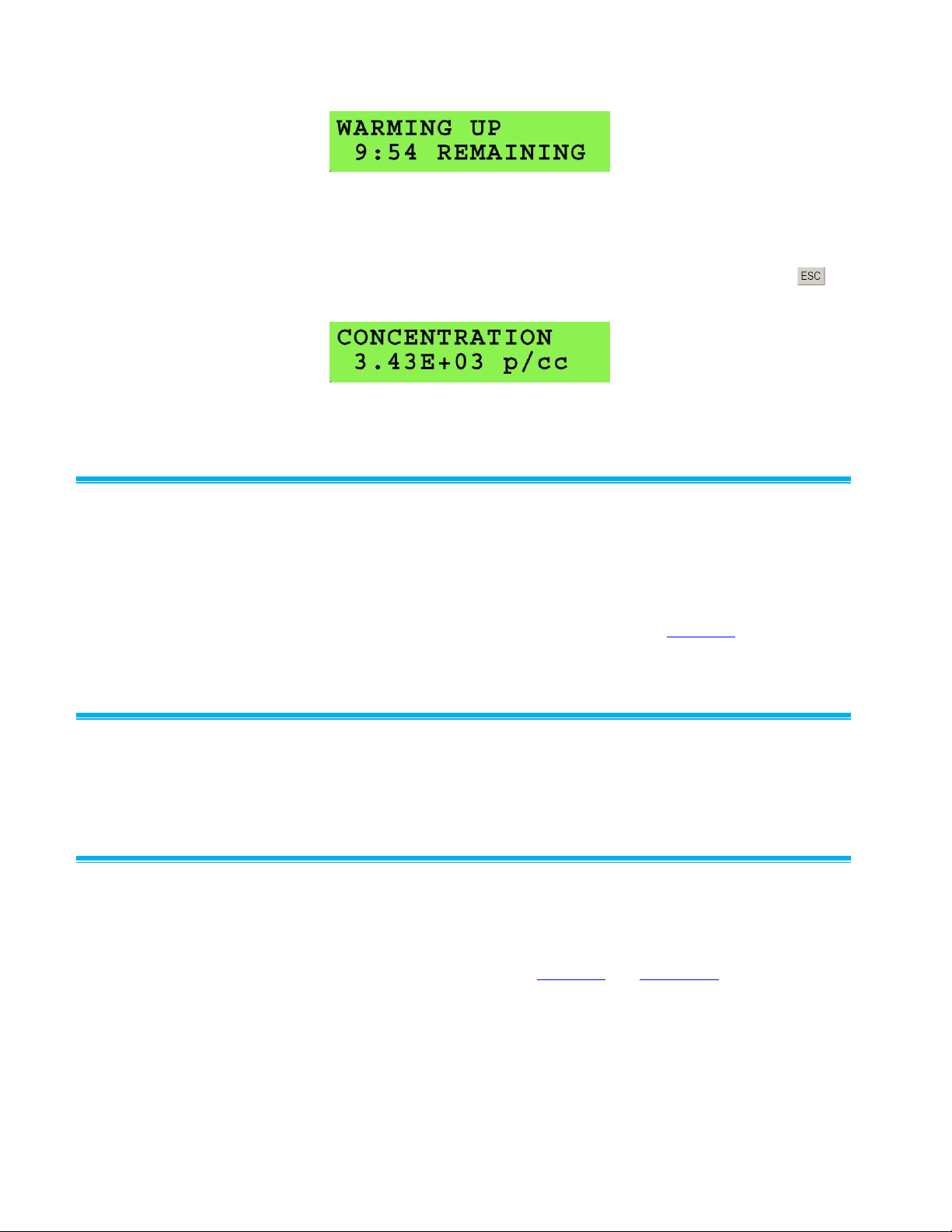
Figure 4-1
Model 3772 Display During Warm-Up
When warm-up is complete, the concentration is automatically displayed
for the 3772 as shown in Figure 4-2. The concentration can also be
displayed before the warm-up is complete by pressing the ESC key at
any time.
Figure 4-2
Model 3772 Display After Warm-Up is Completed
Status Indicator
A status LED indicator on the front panel of the Model 3772/3771 CPC
indicates the overall status of the CPC. It will remain unlit if a key
parameter falls outside of the acceptable operating range. Parameters
monitored include instrument temperatures, pressures, and liquid level.
Generally it will light after warm-up time is complete, an external vacuum is
applied, and butanol has filled the reservoir. See Chapter 8 for
troubleshooting instructions if the Status indicator LED does not turn on.
Particle Indicator
A particle LED indicator light on the front panel of the CPCs indicates
particle counts.
Communication
CPC measurement data, instrument status, and user settings are available
through firmware communication for both Models 3771 and 3772 and also
viewable through the front panel for Model 3772. For more information on
firmware communication, see Chapter 7 and Appendix B.
4-2 Model 3772/3771 Condensation Particle Counter

Model 3772 LCD Display and Keypad
In addition to firmware communication, Model 3772 presents measurement
data, instrument status, and user settings on a 2-line, 16-character,
alphanumeric LCD display. You can navigate the menu options using the
six-button keypad. The display and keypad are shown in Figure 4-3.
Figure 4-3
Model 3772 Front Panel LCD Display and Keypad
Model 3772 Keypad Navigation
As shown in Figure 4-3, the keypad has six keys: scroll left , scroll right
, scroll up , scroll down , Enter , and ESC . Detailed
navigation instructions are described below. Generally,
The up and down arrows are used to scroll through a given menu.
The left and right arrows are used to configure user settings. The new
setting becomes active immediately after the setting is selected.
The Enter
The ESC
key displays submenus.
key returns the display out of a submenu.
The control menu has a two-tier hierarchy. There are four primary
functions: Concentration, User Settings, Status, and Total Count Mode. By
pressing the up or down arrow, the display will scroll through
these four functions.
Two of the primary functions, User Settings and Status, have submenus. A
submenu can be accessed by pressing the Enter key. Once inside a
submenu, the up or down arrow can be used to scroll through the
features. The submenu for User Settings contains all the options for
configuring the CPC. The submenu for Status contains all the parameters
for monitoring the CPC. The primary functions are summarized below
along with their submenus. These are described in detail in the following
sections.
Instrument Operation 4-3

Primary Function
Secondary Submenu
Concentration
Aerosol concentration
measured in [p/cc]
No submenu available.
User Settings
Displays features available
for configuration
Data Logging, Water Removal, Totalizer Time,
Auto Fill, Analog Out, Data Averaging, and Drain.
Status
Displays operating
parameters and status of
CPC
Saturator Temperature, Condenser
Temperature, Optics Temperature, Cabinet
Temperature, Ambient Pressure, Orifice
Pressure, Nozzle Pressure, Laser Current, Liquid
Level, Analog Input 1, Analog Input 2, Flash
Status, USB status, Firmware Version
Total Count Mode
Accumulates particle counts
and clock time
No submenu available.
Concentration
The CPC measures aerosol concentration in particles per cubic centimeter.
The 3772 displays a Concentration screen as shown in Figure 4-3. This is
the default display. Pressing ESC twice from any other screen returns
the display to Concentration screen. The LCD is updated once per second.
For both 3771 and 3772, concentration data can be accessed through
firmware communication using “RD” command. Refer to Chapter 7 and
Appendix B for more information on firmware commands. The maximum
concentration limit for the 3772/3771 is 10,000 particles/cm3.
When concentration exceeds 10,000 particles/cm3 for a 3772, two
exclamation marks appear on the LCD main display, one in front of the
concentration value and one after. For both 3772 and 3771 CPCs,
measurements with concentrations that exceed 10,000 are flagged and the
status LED will be turned off.
4-4 Model 3772/3771 Condensation Particle Counter

Total Count Mode (3772 only)
Total Count Mode allows particle counts to be accumulated and displayed
as shown in Figure 4-4. Total Count Mode is generally useful for tests at
very low particle concentrations (e.g., below 10.0 particles/cm3), such as
evaluation of high efficiency filters.
To access Total Count Mode from the default Concentration screen, press
the down arrow once. When first accessed, the display appears as
shown in Figure 4-5. By pressing Enter , the screen changes to
Figure 4-5. Pressing Enter again at this screen will cycle between
Start, Stop, and Reset. The CPC will count time and total particles once
Start is set. The sample automatically stops when the time is equal to the
Totalizer Time. Totalizer Time can be set in the User Setting submenu.
Figure 4-4
Total Count Mode Data Screen
Figure 4-5
Initial Total Count Mode Data Screen
User Settings
User settings can be configured through firmware commands on both 3772
and 3771. Refer to Chapter 7 and Appendix B for information on firmware
commands. On the 3772, User Settings is also accessible from the front
panel display. It is a primary function accessible from the default
Concentration screen by pressing the up arrow once. The screen
appears as in Figure 4-6. Pressing Enter once brings up the
submenu. Once inside the submenu, the up or down arrow can
be used to scroll through a list of configurable settings. To change a
setting, use the left or right arrow. The setting takes effect
immediately after it is selected. Pressing ESC once returns the display
to User Settings as shown in Figure 4-6. User settings in the menu are
described under individual headings below, beginning with the Data
Logging.
Figure 4-6
User Settings Display
Instrument Operation 4-5

Data Logging (3772 only)
Imp ort a nt Note
The Drain Bottle must be connected for the water removal system to work
properly.
Butanol
Consumption
The water removal feature removes condensed
butanol as well as water, increasing butanol
consumption. The operator may elect not to use
water removal in cool/dry environments to preserve
butanol. When water removal is not used, butanol is
recycled. A full bottle of butanol (1 liter) lasts
approximately 7 days with the water removal system
ON and last 15 days with the water removal system
OFF.
Data can be saved on a Flash memory card on the 3772. By default Data
Logging is “OFF.” To initiate data logging, switch the Data Logging user
setting to “ON” by pressing the left or right arrow once. Logging
will begin immediately. Press the arrow again to toggle Data Logging to
“OFF” to stop. More information on data logging is provided under “Using
the Flash Memory Card.” Use the Data Averaging option in User Settings
to set the data averaging interval for data collection.
Water Removal
The Water Removal option provides ON/OFF control for the water removal
feature of the CPC. The default setting is “OFF.” On the 3772 it can be set
from the Water Removal option in the submenu of User Settings. Pressing
the left
either 3772 or 3771 CPC, it can be turned on using the “SAWR” firmware
command. See Chapter 7 and Appendix B for information on firmware
commands.
Water Removal system is used in hot/humid environments to eliminate
contamination of the butanol working fluid by condensed water vapor.
Water removal keeps the CPC operating at peak performance.
or right arrow toggles Water Removal system on or off. On
Water removal is achieved by collecting all condensate from the cooled
condenser before it has a chance to return and remix with the butanol in
the heated saturator. The collected condensate is pumped to the Drain port
and flows into the supplied Drain Bottle.
4-6 Model 3772/3771 Condensation Particle Counter

Totalizer Time (3772 only)
Option
Concentration Range for Analog Output 0–10 V
Relation
OFF
0 V independent of concentration
-
1E+1
0 to 10 particles/cm3
linear
1E+2
0 to 100 particles/cm3
linear
1E+3
0 to 1,000 particles/cm3
linear
1E+4
0 to 10,000 particles/cm3
linear
OFF
0 V independent of concentration
-
The Totalizer Time feature is available from the User Settings submenu.
Use this feature with the Total Count Mode function to select the time
period for accumulating counts. Three options are available: 1 minute,
60 minutes, and Continuous. The default setting is “Continuous.” Pressing
the left
or right arrow will cycle through these three options. Time
and count accumulation stops once the time is complete. The accumulation
can also be ended manually prior to the end of a sampling period from the
Total Count Mode display.
Auto Fill
When the Auto-Fill option is ON, the instrument fills with butanol
automatically when the liquid level indicator in the butanol reservoir detects
a low butanol level condition. Selecting Auto-Fill OFF prevents the fill valve
from opening despite a low butanol level. Note that a Drain command will
turn Auto-Fill to OFF. Auto-Fill can be turned back on by using the AutoFill setting or by restarting the CPC.
On the 3772, an Auto Fill option is available in the User Setting submenu.
Pressing the left
both 3771 and 3772, Auto-Fill can be set ON or OFF with the “SFILL”
firmware command. See Chapter 7 and Appendix B for more information
on firmware commands.
or right arrow will toggle Auto-Fill ON or OFF. On
Analog Out
The Analog Out setting configures the signal from the “DMA/Analog
Output” port on the back panel. This analog signal is from 0 to 10 V. There
are five options available to select: OFF, 1E+1, 1E+2, 1E+3, 1E+4. The
analog signal is linearly proportional to particle concentration when it is
turned on. The relationship between voltage output and particle
concentration is listed below.
On the 3772, the Analog Out option is available in the User Settings
submenu. Pressing the left
options. The scaling and OFF options are available to the 3771 and 3772
through the “SAO” firmware command. See Chapter 7 and Appendix B for
more information on firmware commands.
or right arrow will cycle through the
Instrument Operation 4-7

Data Averaging (3772 only)
When Data Logging is set to “ON”, data is averaged over selected Data
Averaging Period for saving to the flash memory card. The Data Average
Periods available are 1, 2, 3, 4, 5, 6, 10, 12, 15, 20, 30, or 60 seconds. By
default the Data Average Period is 1 second.
To change the Data Average Period, the Data Logging option first must be
set to “OFF.” Then in the Data Average Period display, press the right
or left arrow to cycle through the available Data Average Periods.
When the desired period is displayed, press ESC to return to the User
Settings screen.
The Aerosol Instrument Manager® software provides more choices for data
average period. See the software manual for details. It is not
recommended you use a Flash Memory Card and Aerosol Instrument
Manager® software or terminal program to collect data simultaneously to
avoid data transfer interference.
Drain
The Drain feature is used as part of the process to drain butanol from the
reservoir. It opens the drain valve and turns Auto-Fill mode OFF. When the
drain is complete, Auto-Fill must be turned back on by using Auto-Fill
setting or by restarting the CPC. For specific instructions on draining
butanol, refer to the section “Draining Butanol from the Butanol Reservoir”
in Chapter 8.
On the 3772 the Drain feature is available from the User Settings
submenu. Pressing the left
OFF. On the 3771 the Drain feature is controlled through the “SDRAIN”
firmware command. Refer to Chapter 7 and Appendix B for further
information on firmware commands.
or right arrow toggles Drain ON or
Status
Status information provides data from instrument sensors useful to confirm
basic performance and for troubleshooting. The Status parameters are
described below, beginning with Saturator Temperature.
Status parameters are accessible through firmware commands for both
CPCs. Refer to Chapter 7 and Appendix B for further information on
firmware commands.
On the 3772, the parameters are also available from the Status menu. To
access the Status menu on 3772, start at the default Concentration screen
and press the up
Figure 4-7. Press the Enter
Toggle through submenus (status parameters) with the up
arrow. Pressing ESC once returns the display to the Status
4-8 Model 3772/3771 Condensation Particle Counter
arrow twice. The Status screen appears as shown in
key to view the submenus for Status.
or down

screen as shown in Figure 4-7. If any of the status parameters deviates
from the normal condition, the status light is off and there are two
exclamation marks around the parameter: one before and one after, as
shown in Figure 4-8.
Figure 4-7
Status Display
Figure 4-8
Status Parameter Display for Diagnostics
Saturator Temp (Temperature)
Saturator temperature is 39.0 °C when the instrument warm up is complete
and the instrument has stabilized. The saturator provides saturated butanol
vapor that mixes with aerosol particles in the condenser.
Condenser Temp (Temperature)
Particle growth occurs in the condenser as butanol vapor from the
saturator is cooled, supersaturated, and condenses on sampled aerosol
particles. The condenser temperature is maintained at 22.0 °C.
Optics Temp (Temperature)
The optics temperature is maintained at 40.0 C. This is above the
saturation temperature and prevents butanol from condensing on the
lenses and other internal components in the particle detection optics.
Cabinet Temp (Temperature)
The cabinet temperature measures the temperature inside the CPC.
Ambient Pressure
Ambient pressure is the barometric air pressure in kPa. Inlet air pressure is
very close to the barometric pressure when sampling directly from the
ambient environment. A restriction at the inlet will change the inlet air
pressure. The instrument is designed to operate with an inlet pressure
between 75 and 105 kPa.
Instrument Operation 4-9

Orifice Pressure
Orifice pressure is the differential pressure across the aerosol flow critical
orifice in kPa. Identification of the orifice is found in the flow schematic
Figure 5-1.
Nozzle Pressure
Nozzle pressure is the differential pressure across the nozzle between the
condenser and the optics chamber in kPa. Identification of the nozzle is
found in the flow schematic
Figure 5-1.
Laser Current
Laser power is monitored by an internal detector in the diode laser
package. If laser light energy drops and the laser current is below 35 mA,
an Error is indicated and the Status light is OFF.
Liquid Level
FULL is indicated if adequate butanol is present in the liquid reservoir.
Liquid level is detected by a heated RTD (Resistance Temperature
Detector) level detector. If the liquid level is low, NOT FULL is indicated.
Analog Inputs
Analog Input 1 and 2 display voltages supplied to the BNC connectors at
the back panel of the instrument. These analog data inputs have a range of
0 to 10 volts. Voltages can come from a variety of sources at the operator’s
discretion. Signals should be gained up or down so the outputs fall into the
0-to-B-volt window with maximum resolution. On both 3772 and 3771
CPCs, analog input data is saved along with concentration data through
firmware commands or to a computer running Aerosol Instrument
Manager® software. On the 3772 analog input data can also be saved to
the Flash Memory Card when a card is present and data logging is ON.
Flash Status (3772 only)
When a flash memory card is present, READY is indicated. When a flash
memory card is present and data logging is ON, LOGGING is indicated.
When there is not a flash memory card, REMOVED is indicated. See more
details below.
USB Status
When the USB port on the back panel of the 3772/3771 CPC is connected,
the status indicates CONNECTED. The status indicates DISCONNECTED
when there is no connection to the USB port.
4-10 Model 3772/3771 Condensation Particle Counter

Firmware Version
This option shows the current firmware version of the instrument.
Using the Flash Memor y Card (3772 only)
Particle concentration data and analog input data can be saved to a Flash
Memory Card inserted in the slot at the middle right of the front panel.
Insert the card with the label facing right.
Data logging is initiated (turned ON) from the front panel under the User
Settings Menu. A file having a .DAT extension is created and will sample
one hour of CPC data. Additional files will be created automatically each
hour, i.e., having one hour of data. A shorter file is created if the test is
stopped by turning Data Logging OFF. Data is lost if an open file is
improperly closed, by turning the instrument off or removing the flash
memory card.
To read saved data to computer, connect the supplied card reader to your
computer using the USB cable. Insert the flash card in the reader. Your
computer will recognize the card reader and display a window showing
several options. Select the option Open folder to view files to access the
test files on the installed memory card. The file names are based on the
date and time when the test was initiated.
The Aerosol Instrument Manager® software described below retrieves files
from the flash memory card for data display. Refer to your Aerosol
Instrument Manager® software instruction manual for information on
importing .DAT data files.
Additional technical information on the flash memory card is found in
Chapter 7.
Notes: Data cannot be saved to the flash memory card and to the
computer through Aerosol Instrument Manager® software
simultaneously.
Keep the amount of data stored in the flash memory card under
64 MB to avoid long overhead time before generating a new data
file each hour in the card.
Flash Memory Card Format
The data card supplied with Model 3772 CPC is formatted as per FAT32
file system. This ensures data is logged and saved properly. Should you
use another external data card, make sure that you reformat the card to the
FAT32 file system before logging data.
Note: Recording data on memory cards not formatted to FAT32 file
system can result in malfunctioning of the data logging system.
This may cause the CPC to freeze at the end of a run and loss of
previously recorded data files.
Instrument Operation 4-11

Follow the steps below to reformat your card:
1. Connect the supplied card reader to your computer using the USB
cable.
2. Insert the flash card in the reader. The flash memory card will appear
as a separate disk drive in Microsoft® Internet Explorer® browser.
3. If you have any data on the flash memory card you want to save, you
must copy it to a temporary directory on your computer, because the
reformat will erase it from the flash card.
4. Put your cursor on the flash memory card’s drive letter in Microsoft®
Internet Explorer® browser and right click. Select Format.
5. Under File System, make sure “FAT32” is selected. Click on Start.
6. When it is done reformatting, copy any files you saved back onto the
flash memory card.
7. You can check the format type of the flash memory card at any time by
right clicking on the drive letter in Microsoft® Internet Explorer®
browser. Select Format and look under File System.
Figure 4-9
Reformatting the Flash Memory Card
4-12 Model 3772/3771 Condensation Particle Counter

C a u t i o n
Remove the flash memory card following the correct procedures:
1. Use Safely Remove Hardware option in Windows to disconnect the
card reader from the computer—stop USB Mass Storage Device.
2. After the message Safe To Remove Hardware: The “USB Mass
Storage Device” device can now be safely removed from the system
appears, physically remove the flash memory card from the card
reader.
Failure to follow these procedures may result in failure to log data with
the flash memory card.
Aerosol Instrument Mana g e r® Software
C a u t i o n
With the vacuum on and butanol in the reservoir, do not tip the counter
more than 10° in any direction. It is recommended to turn off the CPC
and disconnect the butanol fill bottle before the CPC is being moved or
tilted for longer than a few seconds to prevent flooding the sensor.
Aerosol Instrument Manager® software is supplied with the 3772/3771
CPCs. This program provides many useful data acquisition, display,
processing, and download functions used in particle measurements.
Review the supplied Aerosol Instrument Manager® software manual for
complete information on software functions.
Moving and Shippi n g the CPC
Make sure the Model 3772/3771 CPC is turned off and remains upright
while moving the instrument. There is no need to drain the CPC before
moving it. Prior to shipping, however, it is necessary to drain butanol from
the instrument. Refer to “Draining Butanol from the Butanol Reservoir” in
Chapter 8 to drain the CPC.
TSI recommends that you keep the original packaging (carton and foam
inserts) of the CPC for use whenever the CPC is shipped, including when it
is returned to TSI for service. Always seal off the sampling inlet to prevent
debris from entering the instrument and drain and dry the CPC before
shipping.
Instrument Operation 4-13

(This page intentionally left blank)
4-14 Model 3772/3771 Condensation Particle Counter

Theory
C H A P T E R 5
Technical Description
The Model 3772/3771 CPC is a continuous-flow condensation particle
counter that detects particles as small as 10 nanometers (50% detection
efficiency) in diameter. This section describes the function of the CPC, its
subsystems and its components. A discussion of operation theory and
history is given first.
The CPC acts very much like an optical particle counter. However, the
particles are first enlarged by a condensing vapor to form easily detectable
droplets. The science behind the counter, therefore, is focused on how to
condense the vapor onto the particles. Portions of the following discussion
are taken from a paper by Keady et al. [1986].
When the vapor surrounding particles reaches a certain degree of
supersaturation, the vapor begins to condense onto the particles. This is
called heterogeneous condensation. If supersaturation is too high,
condensation can take place even if no particles are present. This is
referred to as homogeneous nucleation or self-nucleation, whereby
molecules of the vapor form clusters due to the natural motion of the gas
and attractive van der Waals forces to form nucleation sites. This condition
is avoided by accurately controlling operating temperatures. The CPC
operates below the supersaturation ratio to avoid homogenous nucleation.
The degree of supersaturation is measured as a saturation ratio (P/Ps),
which is defined as the actual vapor partial-pressure divided by the
saturation vapor pressure for a given temperature:
P
supersaturation = __
Ps
For a given saturation ratio, the vapor can condense onto particles only if
they are large enough. The minimum particle size capable of acting as a
condensation nucleus is called the Kelvin diameter and is evaluated from
the following relationship:
P (4 M)
saturation ratio = __ = exp
Ps
_____
RTd
5-1

where = surface tension of the condensing fluid
M = molecular weight of the condensing fluid
R = universal gas constant
T = absolute temperature
d = Kelvin diameter
The higher the saturation ratio, the smaller the Kelvin diameter.
The saturation vapor pressure Ps is defined for a flat liquid surface. For a
round liquid surface, such as the surface of a droplet, the actual saturation
vapor pressure is greater. In other words, the smaller the droplet, the
easier it is for the vapor molecules to escape the liquid surface. The Kelvin
diameter defines the critical equilibrium diameter at which a pure droplet is
stable—there is neither condensation nor evaporation. Smaller liquid
particles will evaporate and larger particles grow even larger by
condensation. The larger particle will grow until the vapor is depleted,
causing the saturation ratio to fall until it is in equilibrium with the particle
droplet.
If the saturation ratio is controlled to a level below the critical saturation
ratio—the point at which homogeneous nucleation takes place—
condensation will not take place in a particle-free environment.
The lower size sensitivity of the counter is determined by the operating
saturation ratio. For the counter this ratio is several hundred percent,
whereas in the atmosphere, this ratio is only a few percent for water.
= density of the condensing fluid
History
Historically, the counter has been called a condensation nucleus counter
(CNC). CNC technology uses three techniques to cool and supersaturate
the condensing vapor: adiabatic expansion, two-flow mixing, and
diffusional thermal cooling. The Model 3772/3771 CPC uses the latter.
Adiabatic Expansion CNC
The first CNC was developed over a century ago by John Aitken [1888].
His simple and completely mechanical device cooled water-saturated air by
adiabatic expansion using a pump. The droplets were counted as they fell
onto a counting grid and a calculation was made to determine the
concentration of dust particles in the sample volume. He made several
improvements to his invention and his portable dust counter was used for
many years (Aitken [1890–91]).
5-2 Model 3775 Condensation Particle Counter

Other significant developments in adiabatic-expansion CNCs include the
use of electrical photodetectors to measure the light attenuation from cloud
formation (Bradbury and Meuron [1938], Nolan and Pollak [1946], Rich
[1955], Pollak and Metneiks [1959]); the use of under- and overpressure
systems; and automation using electrically controlled valves and flow
systems. The amount of light attenuated from the droplet cloud is
monotonically related to the concentration of particles and is calibrated
either by manual counting techniques, calculated from theory of particle
light-scattering, or by using an electrical classification and counting method
(Liu and Pui [1974]). A historical review of the expansion CNCs is given by
Nolan [1972], Hogan [1979], and Miller and Bodhaine [1982].
Two-Flow Mixing CNC
Another cooling method turbulently mixes two vapor-saturated flows, one
hot and one cold, to rapidly cool and supersaturate the vapor (Kousaka et
al. [1982]). The condensation and droplet growth are fairly rapid and
uniform. The flows can be passed continuously (that is, non-pulsating)
through the mixing chamber onto a single-particle-counting optical
detector.
Diffusional Thermal CNC
A continuous-flow, diffusional, alcohol-based, thermal-cooling CNC
(Bricard et al. [1976], Sinclair and Hoopes [1975], Agarwal and Sem
[1980]) first saturates the air sample with alcohol vapor as the sample
passes over a heated pool of liquid alcohol. The vapor-saturated air stream
flows into a cold condenser tube where the air is cooled by thermal
diffusion. The alcohol condenses onto the particles and the droplets grow
to about 10 to 12 micrometers. The droplets are counted by a singleparticle-counting optical detector.
Continuous-flow, diffusional, water-based CPCs (TSI Model 3781, 3785,
and 3786 WCPCs) were developed between 2003 and 2006. Using a
patented technique (Technology from Aerosol Dynamic Inc., U.S. Patent
No. 6,712,881), an aerosol sample is drawn continuously through a cooled
saturator and then into a heated condenser, where water vapor diffuses to
the centerline of the condenser faster than heat is transferred from the
warm walls, producing supersaturated conditions for water vapor
condensing onto the particles.
Model 3760, 3762, and 3010 was introduced in early 90s and was replaced
by Model 3772/3771 in 2005. The 3772/3771 CPC works only in the single
count mode at relatively high aerosol flow rates of 1.0 and 0.6 L/min
respectively. The 3772/3771 CPC uses n-butyl alcohol as the working fluid
and an external vacuum pump or source to drive the 1 L/min aerosol flow
rate. The 3772/3771 can detect 10 nm particles at 50% detection
efficiency.
For high-concentration measurements, a classical photometric lightscattering technique is used. The first commercial version of this type of
CNC (TSI Model 3020) used n-butyl alcohol as the condensing fluid and
Technical Description 5-3

has a flow rate of 0.3 L/min. TSI’s Model 3020 CNC was replaced in 1988
by the Model 3022A, which was replaced again in 2005 by the Model 3775
CPC. Both the Model 3775 CPC and the 3785 Water-based Condensation
Particle Counter use the photometric mode of operation to monitor high
particle concentrations up to 107 particles/cm3. These CPCs are generalpurpose instruments suitable for a wide variety of applications.
The Model 3025 Ultrafine Condensation Particle Counter (UCPC) was
developed in 1989 and was replaced by the Model 3776 UCPC in 2005.
The 3776 has a lower size detection limit and a higher aerosol flow rate
compared to the 3025A. Both the 3776 UCPC and 3786 UWCPC utilize
sheath-air-flow design to lower the size detection limit. When growing the
particles in the condenser chamber, the highest saturation ratio occurs on
the centerline of the flow stream at some distance down the condensing
tube (Stolzenburg [1988]). Although the saturation ratio is not uniform
across the flow profile due to thermal gradients, the lower size-sensitivity
can still be predicted and measured. Using sheath air, the UCPC confines
the aerosol to the centerline of the condenser tube where level of
supersaturation is the highest. The result is very high detection efficiency
for small particles. The high sensitivity of the Model 3776 UCPC and the
Model 3786 UWCPC makes them the only instruments of their kind that
can detect particulates down to 2.5 nm. This makes them useful for atmospheric studies, nucleation, cleanroom monitoring, and basic aerosol
research, etc. The sheath-air-flow design of the two CPCs also significantly
reduces the response time for particle detection and particle diffusion
losses. This occurs because aerosol particles are routed directly from the
inlet to the condenser and optics, not through the saturator.
The Model 3781 WCPC is a small size and light weight instrument that
detects particles down to 6 nm and operates in single count mode for
concentrations up to 5 105 particles/cm3.
The Model 3007 CPC was developed in 2001. It is a hand-held, battery
powered instrument with a size detection limit of 10 nm. It uses isopropyl
alcohol as the working fluid.
Currently, five CPCs (Models 3772, 3775, 3776, 3785, and 3786) are also
commonly used with submicron size-distribution measurement systems
such as the Scanning Mobility Particle SizerTM (SMPSTM) Spectrometers
(TSI Model 3936).
5-4 Model 3775 Condensation Particle Counter

Design of the CPC
The basic instrument consists of three major subsystems: the sensor, the
microprocessor-based signal-processing electronics, and the flow system.
The sensor and the flow system are described below.
Sensor
The sensor is made up of saturator, condenser, and optical detector,
shown schematically in Figure 5-1. The sensor grows the sampled aerosol
particles into larger droplets and detects them optically. The laminar
aerosol flow enters the saturator section where it passes through a heated,
liquid-soaked cylindrical wick. The liquid evaporates and saturates the air
flow with butanol vapor. Butanol is replenished from a reservoir and a fill
bottle.
The flow of combined aerosol and butanol vapor is then cooled using a
thermoelectric device (TED) in the condenser. The vapor becomes
supersaturated and condenses on the aerosol particles (condensation
nuclei) to form larger droplets. The droplets pass from the condenser tube
through a nozzle into the optical detector. Liquid that condenses on the
walls of the condenser tube runs back down and is removed by the water
removal system into the drain bottle when the system is ON. Otherwise,
the liquid goes back into the saturator and is absorbed into the wick for
reuse.
The sensor’s optical detector is comprised of a laser diode, collimating
lens, cylindrical lens, collection lenses, and photodiode detector. The laser
and collimating lens form a horizontal ribbon of laser light above the
aerosol exit nozzle. The collection lenses and detector incorporate a pair of
aspheric lenses that collect the light scattered by the droplets and focus the
light onto a low-noise photodiode. A reference photodiode is used to
maintain constant laser power output. The surface temperature of the
optics housing is maintained at a higher level than the saturator to avoid
condensation on the lens surfaces.
The Model 3772/3771 CPC operates in single particle count mode up to
104 particles/cm3. Rather than simply counting individual electrical pulses
generated by light scattered from individual droplets, the CPC uses a
continuous, live-time coincidence correction to improve counting accuracy
at high particle concentrations. Coincidence occurs when the presence of
one particle obscures the presence of another particle creating an
undercounting error. “Live-Time Counting” is discussed later in Chapter 6.
This option can be turned OFF by firmware command “SCC,0”.
Technical Description 5-5

Figure 5-1
Flow Schematic of the Model 3772/3771 CPC
5-6 Model 3775 Condensation Particle Counter

Critical Flow
528.0
P
P
U
D
pressure Critical
528.0
NA
ONA
To achieve the 1.0 L/min critical aerosol flow through the sensor, an orifice
is used, operated at the critical pressure ratio to provide a critical flow.
Critical flow is very stable and is a constant volumetric flow, assuring
accurate concentration measurements despite varied inlet pressure.
The critical pressure ratio is found by dividing the absolute pressure
downstream of the orifice PD, by the absolute pressure upstream of the
orifice PU. This ratio must be below 0.528 for air.
Values for pressures impacting CPC flow can be obtained using firmware
commands for both 3772 and 3771 CPCs. They are also found on the
Status menu on the front panel display for 3772. These pressures are
identified as the Ambient pressure, the Orifice pressure, and the Nozzle
pressure. The ambient pressure is typically the barometric pressure at the
inlet. The orifice pressure is the differential pressure across the aerosol
flow orifice. The nozzle pressure is the differential pressure across the
nozzle. Figure 5-1 identifies the location of the pressure transducer sample
ports.
To verify that critical pressure (therefore critical flow) is achieved under
extremes in inlet resistance, determine the orifice upstream pressure from
(A – N). The downstream pressure is the upstream pressure minus the
orifice differential pressure (A – N – O).
Flow is critical if the following is true:
(5-1)
Vacuum source, either a central building vacuum or a stand-alone vacuum
source (e.g., TSI Model 3032 Vacuum Pump), should provide at least 60
kPa (18 in. Hg) vacuum and 1.0 L/min critical volumetric flow at the inlet of
each CPC supported. The flow in the CPC is regulated by a critical orifice.
Changes in the inlet pressure will not affect the flow rate through the
instrument. A vacuum source that can provide a higher volumetric flow
(e.g., TSI Model 3033 Vacuum Pump) is needed when running multiple
CPCs.
Technical Description 5-7

Counting Efficiency and R esponse Time of the 3772/3771 CPC
The 3772/3771 CPC has a D50 of 10 nm. D50 is defined as the particle
diameter at which 50% of particles are detected. The curve fit shown in
Figure 5-2 is based on testing of three 3772/3771 CPCs using sucrose
particles generated by TSI Model 3480 Electrospray Aerosol Generator
and size classified with TSI Model 3080 Electrostatic Classifier and Model
3085 Nano Differential Mobility Analyzer (DMA) . The counting efficiency is
calculated by comparing the CPC readings to TSI Model 3068A Aerosol
Electrometer readings.
Note the particle concentration measured by the CPC is the total number
concentration of all particles that a CPC can detect. This measurement
provides no size differentiation and it is not corrected using the CPC
counting efficiency curve. When the 3772 CPC is used as part of a
Scanning Mobility Particle Sizer (TSI Model 3936 SMPS), the counting
efficiency curve is used to correct particle count data to provide particle
size distribution.
The 3772/3771 CPC has a fast response time. T95, defined as the time it
takes for the CPC reading to reach 95% of a concentration step change, is
about 3 sec for the 3772/3771 CPC. Figure 5-3 shows the response time
curves. The curves are based on averaging of three CPCs.
Figure 5-2
Counting Efficiency Curve of 3772/3771 CPC
5-8 Model 3775 Condensation Particle Counter

Figure 5-3
Response Time of 3772/3771 CPC
Technical Description 5-9

(This page intentionally left blank)
5-10 Model 3775 Condensation Particle Counter

C H A P T E R 6
Particle Counting
This chapter discusses specific aspects of particle counting and particle
count measurements performed using the Model 3772/3771 Condensation
Particle Counter (CPC).
The Model 3772 CPC has two modes for particle counting:
Concentration mode, where data is presented as particle concentration
in p/cc, updated each second on the display (the maximum time
resolution is tenth of a second).
Total Count Mode (Totalizer Mode), where total particle counts are
accumulated and presented each second.
The Model 3771 CPC has the Concentration mode and is capable of Total
Count Mode using the Aerosol Instrument Manager® software.
Concentration mode is commonly used for most applications. Total Count
Mode is used at very low particle concentrations. Particles can be
accumulated until a desired statistical accuracy is achieved. Refer to the
section below discussing total count accuracy.
In the concentration mode, the CPC operates in the single count mode with
continuous, live-time coincidence correction over the range between 0 and
104 particles per cubic centimeter.
Optical Detection
Submicrometer particles are drawn into the counter and enlarged by
condensation of a supersaturated vapor into droplets that measure several
micrometers in diameter. The droplets pass through a lighted viewing
volume where they scatter light. The scattered-light pulses are collected by
a photodetector and converted into electrical pulses. The electrical pulses
are then counted and their rate (live-time corrected) is a measure of
particle concentration.
6-1

Total Count Accuracy
.n
r
tQ
n
sensor the inflow aerosol of volume
counts total
ionconcentrat
rateflow aerosoltime-live daccumulate
particles counted of number 1
C
a
At very low concentrations, the accuracy of the measurement in the singleparticle-counting mode is limited by statistical error. If the total number of
particles counted in each time interval is very small, the uncertainty in the
count is large. The relative statistical error of the count
total count n by
In total count mode (or totalizer mode), the accuracy of the concentration is
increased by sampling for a longer period and counting more particles. The
concentration is calculated by:
where
Q = Aerosol flow rate, nominally 1000 cm3/min (16.7 cm3/sec).
t = sample time in sec.
Live-Time Counting
is related to the
r
Coincidence occurs when more than one particle occupies the optical
sensing region simultaneously. The optical detector cannot discriminate
between the particles and multiple particles are counted as a single
particle. At higher particle concentrations, particle coincidence begins to
significantly impact the measured concentration.
The CPC corrects for coincidence continuously with the instrument
electronics performing a “live-time” correction. Live-time refers to the time
between electrical pulses. This is the total measurement time interval
minus the time during which the counter is disabled with one or multiple
particles in the optical sensing volume (the Dead Time). The dead time
should not be included in the sample time since particles can’t be counted
during this time interval except the ones that are already in the viewing
volume. The actual particle concentration therefore equals the number of
counted particles divided by the live time and the aerosol flow rate.
To measure live time, a high-speed clock and accumulator are used. The
accumulator adds up the live time and the counter adds up pulse counts.
The particle concentration is then calculated by
This option can be turned off by firmware command “SCC,0”.
6-2 Model 3772/3771 Condensation Particle Counter

Coincidence Correction for Pulse Output
C a u t i o n
At concentrations above 10,000, two exclamation marks appear at the
sides of the concentration reading on the front panel of the 3772. If this
occurs, the number of particles shown on the display could be lower than
the actual concentration.
Live-time coincidence correction is not available if you are using the pulse
output from the CPC which only provides raw counts of the particles.
Concentration can be calculated using raw counts and the aerosol flow rate
of the CPC. This concentration is only accurate for low particle
concentrations when coincidence level is low, e.g., in clean air or after a
filter. If the pulse output is used for higher concentration up to 104
particles/cm3, the following calculation improves the accuracy of the
particle concentration obtained from pulse output:
Na = Ni exp (NaQp)
where Na = the actual concentration (particles/cm3)
Ni = the indicated concentration (particles/cm3)
Q = 16.67 cm3/s
p = 0.35 microsecond is the nominal effective time each
particle resides in the viewing volume
The Na in the exponent can be approximated by Ni.
Table 6-1 shows the calculated coincidence for several concentrations.
Coincidence is 1-Na/Ni.
Table 6-1
Coincidence Levels Based on 0.35 µsec Pulse Width
Concentration Calculated Coincidence
(particles/cm3) (%)
10 >.01
100 .06
1000 .59
5000 3.05
10000 6.4
Concentrations obtained from pulse width and coincidence-corrected with
the above equation are slightly different from the live-time corrected
concentrations on the front panel display. The former concentration is
corrected based on nominal pulse width but the latter is corrected based on
the actual pulse widths for particles. For concentrations above those in
Table 6-1, contact TSI Incorporated for a more suitable particle counter.
Particle Counting 6-3

Particle Size Selector
The particle size selector (Model 376060 PSS) is an accessory (not
included) to the Model 3772/3771 CPC to let you choose any of 11 cutoff
sizes between 0.010 and 0.122 micrometer. The PSS uses a series of finemesh screens to remove small particles by diffusional capture. An
additional set of diffusion screens (available separately, Model 376061) lets
you select cutoff diameters up to 0.25 micrometer. The cutoff sizes listed
below are calculated using efficiencies for 3772/3771 CPC and diffusion
screens.
Diffusion Particle size cut,
screens μm (50%)
0 0.010
1 0.020
2 0.031
3 0.041
4 0.052
5 0.062
6 0.072
7 0.083
8 0.092
9 0.102
10 0.112
11 0.122
6-4 Model 3772/3771 Condensation Particle Counter

C H A P T E R 7
Computer Interface
and Commands
This chapter provides computer interface and communications information
for the Model 3772/3771 Condensation Particle Counter (CPC).
Information on the Flash Memory Card for the 3772 is also provided.
Computer Interface
This section includes descriptions on USB, Ethernet connections, RS-232,
and the Flash Memory Card (3772 only).
USB
USB communications are provided with the 3772/3771 CPC, for use with
the supplied Aerosol Instrument Manager® software. Simply connect the
supplied USB cable to the instrument and computer having Windows®based operating system and the Aerosol Instrument Manager® software.
Refer to the Aerosol Instrument Manager manual for specific system
requirements, including operating system version.
Ethernet
The Ethernet port on the CPC can provide system status information over
the internet and is updated every five seconds. Your web browser must
support java plug-ins.
Network Setup
1. Connect the CPC to the network using an Ethernet cable and turn the
instrument on.
2. On the computer that is connected to the same network using another
Ethernet cable, run the device discovery program Discovery.exe
found on the supplied Aerosol Instrument Manager® Software CD or in
the folder where the Aerosol Instrument Manager software is installed.
This Discovery.exe program will find CPC devices on the network.
Note: This program will only find CPCs that are on the same subnet.
Example: If the computer is at IP address 10.1.3.1, the device
discovery program will find all CPCs on 10.1.3.x. Also, if the
7-1

Windows® firewall is enabled (on by default in service pack 2),
the device discovery will not find any CPCs. Once the IP
address is known, you can access the CPC from another
subnet.
3. Select the device and choose Configure network settings.
Figure 7-1
Digi Device Discovery Screen
4. Talk with your network administrator to verify the correct network
settings this device should operate at. If needed, the MAC address can
be located on the back of the instrument or in this pop-up window. Fill
in the appropriate information and click Save.
®
Windows is a registered trademark of Microsoft Corporation.
7-2 Model 3772/3771 Condensation Particle Counter

Figure 7-2
Configure Network Settings Screen
5. Close the device discovery program and restart the CPC. It takes
about a minute for the Ethernet to initialize.
6. If the CPC is in the same subnet as the computer, start the device
discovery program Discovery.exe and click on Open web interface.
The username and password are “tsicpc” as shown below in
Figure 7-3. If the CPC is not in the same subnet as the computer, type
in the IP address in your web browser. Work with your network
administrator to make sure the IP address is accessible from the
network your computer is in.
Figure 7-3
Digi Connect ME Configuration and Management Screen
Computer Interface and Commands 7-3

7. From the web interface of the device discovery program or the web
browser, you can monitor the status of the CPC.
Figure 7-4
Main Screen HTML Page
7-4 Model 3772/3771 Condensation Particle Counter

Flash Memory Card Specification (3772 only)
A file is created on the Flash Memory Card when the Data Logging option
is turned ON from the front panel of the 3772. Each file will contain one
hour of data, unless the run is stopped early with the STOP option. See
Chapter 4.
Each file has this format:
LINE 1: “TSI CPC DATA VERSION 1”
LINE 2: start time of this file (the first number is the total number of
seconds elapsed from midnight Jan. 1, 1970)
LINE 3: data average interval in seconds
LINE 4: Instrument model number, firmware version number, instrument
serial number (result of the “RV” command)
LINE 5: first data set
LINE 6: second data set
LINE X: last data set
The data sets are defined as counts, concentration, analog input 1, analog
input 2, status. These data sets are saved every average interval so if the
average interval was one minute, the counts would be total counts
(coincidence-corrected) over the last minute, etc. Instrument operates in
normal condition if the status bit shows zero. A nonzero status indicates
that some operating parameters deviate from normal conditions. See RIE
command in Appendix B.
Every time a user begins a new run, a unique file will be created with the
date and time as the file name.
Www_Mmm_dd_hh_mm_ss_yyyy
Where Www is the weekday, Mmm the month in letters, dd the day of the
month, hh_mm_ss the time, and yyyy the year.
Disclaimer: Due to the fact that the FAT file systems are by design not
power fail-safe, if power is lost, part or all of the file system may be lost.
Note: Keep the amount of data stored in the flash memory card under
64 MB to avoid long overhead time before generating a new data
file each hour in the card.
Flash Memory Card Formatting Issue
On Model 3772 CPCs shipped before January 2008, the unit’s internal
flash memory card had a formatting issue. This caused the card to appear
full when the number of logged data files got much above 100, which
resulted in the unit freezing up at the end of taking run data. To solve this
issue, follow the steps below to reformat the card.
1. Power on the instrument and connect a USB cable to it from your
computer. The flash memory card will appear as a separate disk drive
in Microsoft® Internet Explorer® browser.
Computer Interface and Commands 7-5
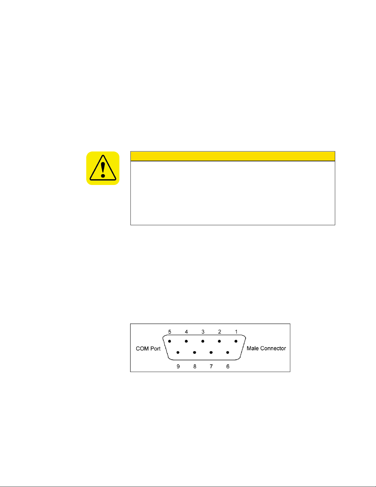
2. If you have any data on the flash memory card you want to save, you
C a u t i o n
Remove the flash memory card following the correct procedures:
1. Use Safely Remove Hardware option in Windows to disconnect the
card reader from the computer—stop USB Mass Storage Device.
2. After the message Safe To Remove Hardware: The “USB Mass
Storage Device” device can now be safely removed from the system
appears, physically remove the flash memory card from the card
reader.
Failure to follow these procedures may result in failure to log data with
the flash memory card.
must copy it to a temporary directory on your computer, because the
reformat will erase it from the flash card.
3. Put your cursor on the flash memory card’s drive letter in Microsoft®
Internet Explorer® browser and right click. Select Format.
4. Under File System, make sure “FAT32” is selected. Click on Start.
5. When it is done reformatting, copy any files you saved back onto the
flash memory card.
6. You can check the format type of the flash memory card at any time by
right clicking on the drive letter in Microsoft® Internet Explorer®
browser. Select Properties and look under File System.
RS-232 Serial Communications
The communications ports are configured at the factory to work with
RS-232-type devices. RS-232 is a popular communications standard
supported by many mainframe computers and most personal computers.
The Model 3772/3771 CPC has two A-pin, D-type subminiature connectors
on the back panel labeled Serial 1 and Serial 2. Figure 7-5 shows the
connector pins on the serial ports; Table 7-1 lists the signal connections.
Note: This pin configuration is compatible with the standard IBM PC serial
cables.
Figure 7-5
RS-232 Connector Pin Designations
7-6 Model 3772/3771 Condensation Particle Counter

Commands
Table 7-1
Signal Connections for RS-232 Configurations
Pin Number RS-232 Signal
1 GND
2 Transmit Output
3 Receive Input
4 (Reserved)
5 GND
6 —
7 —
8 —
9 —
An external computer is connected to Serial 1 for basic instrument
communications and when Aerosol Instrument Manager® software is used.
Serial 2 is used for attaching another instrument. Read and write
commands are sent and received from Serial 2 by the computer connected
to Serial 1. Serial 1 and Serial 2 can have different baud rates and
communications protocols. Normally, only Serial 1 is used.
All commands and responses, unless specified as binary-encoded, are
sent or received as ASCII characters. All messages are terminated with a
<CR> (0x0D) character. All linefeeds (0x0A) characters are ignored and
none are transmitted. Commands are case insensitive. Backspace
character (0x08) will delete previous characters in buffer.
In this specification, values enclosed by “<>” indicate ASCII
characters/values sent/received. For example, <,> indicates the comma
was sent or received via the communications channel.
Integers are 32-bit values. Floating point are IEEE() 32-bit values.
Integer and floating point values are ‘C’ string compatible ASCIIencoded. For example, an integer value of
<11011100101110101001100001110110> binary, would be sent as
<3703216246>.
When char, integer or hex-decimal data is sent with more than one digit,
leading zeros should always be left off. If the value of the data is zero,
then one zero must be sent. An exception is the value zero in real format,
it should be sent as 00000E0.
The firmware commands are divided into the following categories:
READ Commands
SET Commands
MISC (MISCELLANEOUS) Commands
HELP Commands
Computer Interface and Commands 7-7

READ commands are used to read parameter from the instrument (flow
rates, pressures, temperatures, etc.). READ commands can be identified
by a leading "R".
SET commands set an internal parameter to the value(s) supplied with
the command. Supplied parameters are always delimited by a “<,>”. SET
commands can be identified by a leading "S". The instrument will reply to
all set commands with the string “OK” <CR>.
MISC (MISCELLANEOUS) commands will be used for calibration and
SMPS mostly.
HELP commands. A list of firmware commands are accessible using the
HELP command sent to Serial 1 of the CPC. The firmware commands
are also listed in Appendix B. The commands can be used to read CPC
data, instrument statuses, set instrument operating parameters, and
send and receive data from another instrument attached to the Serial 2
port.
The instrument will reply with a serial string of "ERROR", if a command
was not understood.
To use the HELP commands and the firmware commands, a program
capable of sending and receiving ASCII text commands can be used. A
terminal program such as “HyperTerminal” (supplied with Windows®) is
appropriate.
Connect to Serial 1 of the Model 3772/3771 CPC and perform the following
steps:
1. Open the HyperTerminal program by selecting:
Start|Programs|Accessories|Communications|
HyperTerminal.
2. Enter a name for the connection, for example, TSI-3772.
7-8 Model 3772/3771 Condensation Particle Counter

Figure 7-6
Connection Description Screen
3. Enter the communications (COM) port.
Figure 7-7
Connect To Dialog Box
4. Enter the port settings described below and click OK.
Computer Interface and Commands 7-9

Figure 7-8
Port Settings Dialog Box
5. Under the settings tab, pick the ASCII Setup button and check the
boxes shown below.
Figure 7-9
ASCII Setup Dialog Box
7-10 Model 3772/3771 Condensation Particle Counter

6. Now select File|Save As and save the file to the desktop for easy
access.
7. Close the program and start it again from the desktop. It should
automatically open a connection to the instrument.
8. Type in firmware commands to communicate with the CPC. A list of
firmware commands can be obtained using the HELP commands or
from Appendix B. To obtain the list from HELP command, select
Transfer|Capture Text… and then HELP ALL in the terminal window
lets you capture all the help commands to a text file for easy reference.
Computer Interface and Commands 7-11

(This page intentionally left blank)
7-12 Model 3772/3771 Condensation Particle Counter

W A R N I N G
Procedures described below may require removal of the instrument
cover. The instrument must be unplugged prior to service to prevent
possible electrical shock hazard.
W A R N I N G
Unplug the instrument prior to removing the cover to avoid potential of
exposure to laser radiation.
C a u t i o n
Whenever performing service on internal components avoid damage to
the EECPC circuitry by not stressing internal wiring, through bumping,
snagging or pulling. Also use electrostatic discharge (ESD) precautions:
Use only a table top with a grounded conducting surface.
Wear a grounded, static-discharging wrist strap
C H A P T E R 8
Maintenance and
Service
This chapter is written for a service technician with skills in both electronics
and mechanics. Static preventative measures should be observed when
handling any printed circuit board connectors.
Regular maintenance of the Model 3772/3771 Condensation Particle
Counter (CPC) will help ensure years of useful operation. The frequency of
service depends on the frequency of use and the cleanliness of the air
measured. This section describes how to check and service some
components of the CPC.
You are encouraged to call TSI for assistance in performing special
maintenance. It may also be helpful to have the technician, tools, and the
CPC close to the telephone when discussing the problem with a TSI
technician. Refer to this chapter for directions on contacting a technical
resource at TSI.
8-1

Replacement Parts Kits
TSI Part No.
Name
Description
1031513
Replacement Filter
Kit, CPC 3772 and
3771
Kit of all filters
used within the
CPC.
1031514
Replacement
saturator wick kit,
CPC 3772 and
3771
Two (2)
replacement
wicks and Orings for the
removable
saturator base.
1031515
Maintenance Kit
Model, CPC 3772
and 3771.
All items listed
above.
In addition to replacement parts found in your supplied accessory kit,
replacement items are also available from TSI to keep your CPC operating
for many years. Parts are available in kits listed below. Please contact your
TSI representative for details and purchase of these items.
Table 8-1
3772/3771 CPC Maintenance and Replacement Kits
8-2 Model 3772/3771 Condensation Particle Counter

TSI Part No.
Name
Description
1031548
Fill/Drain Bottle Kit,
CPC 3772 and
3771
Fill and drain
bottles, bracket,
vacuum drain
cap, tubing and
fittings.
1031492
Kit, Charcoal Filter,
large, CPC
Five (5) large
charcoal filters
used to remove
butanol from
exhaust (~tenday effectiveness
for each filter).
1031493
Kit, Charcoal Filter,
small, CPC
Five (5) small
charcoal filters
used to remove
butanol from
exhaust (~twoday effectiveness
for each filter).
Maintenance and Service 8-3

Draining Butanol from t he Butanol
5. A special vacuum drain bottle cap is
provided in the accessory kit to facilitate
butanol draining using a vacuum
source. Figure 8-1 shows the special
cap, which consists of a vacuum port
and a Balston filter. The Balston filter
provides a bypass flow path. Connect
the external vacuum source to the
vacuum port. Connect the drain line to
the Drain port on the CPC. When drain
valve is open and vacuum is applied,
the vacuum helps to pull excess
butanol from the internal butanol
reservoir and the wick. Exhaust from
the external vacuum source contains
butanol vapor and must be directed
away from work spaces.
6. The butanol reservoir in the 3772 and
3771 CPCs is much smaller than the
reservoir in predecessor models 3010,
3760, or 3762. The total volume
drained from the reservoir and tubing
is typically less than 7 ml. During
draining, Auto-Fill is automatically
turned off.
Figure 8-1
Vacuum Drain Cap Assembly
Reservoir
Butanol must be drained from the butanol reservoir prior to removing the
saturator base and wick from the bottom of the CPC. To drain the butanol
reservoir:
1. Connect butanol drain bottle (from the accessories) to the drain fitting
on the back of the CPC using the mating quick-connect fitting.
2. Place the drain bottle on the floor.
3. The Drain can be initiated by using the “SDRAIN” firmware command
on 3771 or by using the User Settings menu on the 3772. Detailed
instructions for initiating the manual Drain for the 3772 are provided in
Chapter 4.
4. The butanol drain valve will open. Often there is not a significant
column of liquid in the butanol drain line to initiate flow from the butanol
reservoir. Tipping the instrument toward the drain port and squeezing
the butanol drain bottle will sometimes help start flow. When releasing
the squeezed drain bottle, plug the hole on the bottle cap to create a
vacuum and to initiate draining.
8-4 Model 3772/3771 Condensation Particle Counter
Note: When draining is stopped, the Auto-Fill must be turned on again
by selecting this option from the User Settings menu for 3772 or
through “SFill” firmware command for 3772 and 3771.
Restarting the CPC can also turn Auto-Fill on.

Whenever the instrument is turned on, the Auto-Fill is activated. Do not
run the instrument with the saturator base and wick removed to prevent
spilling butanol from the butanol reservoir.
Changing the Filters
The CPCs use three liquid filters. The liquid filters are for butanol fill,
butanol drain, and the water removal system. The filter in the water
removal system is called Micro-pump filter. These filters may require
replacement at intervals that depend on usage. As a general estimate the
butanol fill filter needs to be replaced after every 2000 hours of usage,
while the other two are replaced only as needed. Replacement filters are
supplied in the accessory kit and are available from TSI as maintenance
kits. Refer to the earlier section Replacement Parts Kits.
Butanol Fill and Drain Filters
The butanol fill filter is found in the fill line leading from the butanol fill bottle
to the fill solenoid valve. The butanol drain filter is found in the line between
the reservoir and the drain solenoid valve (Figure 8-2).
Caution
1. Read warnings and cautions at the beginning of this chapter.
2. Unplug the instrument and lift off the cover by first removing the cover
screws.
3. Find the filter shown in Figure 8-2.
4. Remove the tubing from the barbed fittings at the back and front of the
filter.
5. Replace the filter with the 73 µm filter (P/N 1602088) found in the
accessory kit. This filter has no preferred direction.
Figure 8-2
Replacing the Butanol Fill and Drain Filters
Maintenance and Service 8-5

Micro Pump Filter
MicroPump Filter
The Micro-pump is used to remove condensed water vapor before it
contaminates butanol in the saturator. The micro-pump filter protects the
pump from contamination which could impede its performance. This filter
should generally be replaced only if it becomes blocked. A blocked micropump filter prevents condensate from being extracted.
When using the water removal feature it is advisable to check the drain
tubing to the drain bottle to verify liquid movement. The liquid column will
pulse a small amount toward the drain bottle, approximately once per
second as the micro-pump actuates. If no pulsing occurs, first verify that
the water removal feature is on (see User Settings in Chapter 4). If the
feature is on and no liquid flows in the liquid column, the micro-pump filter
needs to be changed.
1. Read the warnings and cautions at the beginning of this chapter.
2. Unplug the instrument and lift off the cover by first removing the cover
screws.
3. Find the filter shown in Figure 8-3.
4. Remove the tubing from the barbed fittings at the back and front of the
filter.
5. Replace the filter with the 25 µm filter (P/N 1500192) found in the
accessory kit. This filter has no preferred direction.
Figure 8-3
Replacing the Micro Pump Filter
8-6 Model 3772/3771 Condensation Particle Counter

Removing and Installing t h e Saturator
C a u t i o n
Removing the saturator wick will cause butanol (butyl-alcohol) vapors to
diffuse into the work space. Wick replacement operations must be
performed in a well ventilated area, ideally under a fume hood. If
unfamiliar with butanol, refer to the Chemical Safety information at the
front of this manual.
C a u t i o n
Whenever the instrument is turned on, the Auto-Fill is activated. Do not
run the instrument with the saturator assembly removed to prevent spilling
butanol from the butanol reservoir.
Wick
Tools Needed
Plastic bag with seal, Phillips-head screwdriver, and paper towels. Refer to
figures that follow.
To remove and reinstall the saturator wick, follow the instructions below.
1. Find a plastic bag with seal, suitable to hold the 3” 1.75” saturator wick.
The wick will likely be wet with butanol when removed and needs to be
placed in the bag immediately to reduce release of butanol vapors.
2. Connect the Drain Bottle to the drain port at the back of the instrument.
3. Initiate the Manual Drain option as described in “Draining Butanol from
the Butanol Reservoir” section.
4. Once drained, turn the CPC off and remove the vacuum source from the
external vacuum port.
5. Remove the inlet screw indicated in Figure 8-4 on the front panel and
pull out the inlet tube. The inlet tube will not pull all the way out. It will
stop when it has cleared the saturator block, approximately half an inch.
Figure 8-4
Inlet Tube
Maintenance and Service 8-7

6. To access the saturator base on the bottom panel, tilt the CPC on its
7. Remove the
three screws
which hold the
base in the
saturator block
as shown in
Figure 8-5.
Release the
handle in the
base by
loosening the
thumbscrew.
Remove
Screw
Release
Saturator
Figure 8-5
Wick Removal
8. Using the saturator
handle, pull the
saturator base straight
out. The wick is
attached and will be
removed with the
base. It will be snug
but avoid using a
twisting motion.
9. Remove the 2-inch
screw securing the
wick to the base as
indicated in
Figure 8-6. Pull the
wick straight off the
base. Avoid using a
twisting motion
because the wick is
keyed onto the base
with dowel pins and
the soft wick material
can rip.
Figure 8-6
Removing the Wick from the Saturator Base
side so it is lying on the table. Place paper towels on the table under
the saturator base to absorb any butanol that spills out. Do not turn it
upside down.
8-8 Model 3772/3771 Condensation Particle Counter
10. Place the wick in the plastic bag and seal the bag. Replace the
11. To install a wick back into the CPC, confirm that four O-rings on the
saturator base in the CPC prior to shipping. This will prevent the
aerosol path from becoming contaminated. Re-secure the inlet tube.
The wick can be dried by putting it in a vacuum for three hours.
However, it is not necessary to dry the wick before putting it back into
the saturator block after the shipment.
saturator base are in place and undamaged. Replacement O-rings are
provided in the accessory kit if an O-ring on the saturator base
becomes lost or damaged. Figure 8-7 shows the two outer O-rings
(P/N 2501172, 2501569) and Figure 8-8 shows the two inner O-rings
(P/N 2500021).

Figure 8-7
O-Rings on Saturator Base (P/N 2501172 and 2501569)
Figure 8-8
O-Rings on Saturator Base (P/N 2500021)
12. Slide the wick back onto the saturator base using the two dowel pins to
key it. This will keep the holes aligned as the wick is replaced in the
CPC. Replace the 2-inch screw and washer.
13. Keep the CPC turned off and the vacuum supply disconnected from
the external vacuum port on the back panel. Tilt the CPC on its side to
access the bottom panel. The CPC can lie flat on its side but do not
turn it upside down.
14. Reinsert the wick and base and secure to CPC using the three screws
indicated in Figure 8-5. In case the wick does not insert easily, follow
these tips:
i. If the CPC has recently been turned off, the saturator may still be
warm. Let the saturator cool down to room temperature before
inserting the wick.
ii. Apply Krytox O-ring grease (accessory kit) to the bottom O-ring
only. Do not use silicon-based O-ring grease.
15. Reinsert the inlet tube and secure the sleeve with the screw indicated
in Figure 8-4.
Maintenance and Service 8-9

16. Turn on the instrument and use the Auto-Fill option to refill the
reservoir with butanol. See “User Settings” in Chapter 4.
Verifying Flow Rate
To measure the instrument sample flow rate, connect a low pressure-drop
flowmeter to the CPC inlet. A bubble flowmeter or a thermal flowmeter
works best. A TSI mass flowmeter also works because it is corrected for
atmospheric pressure to give volumetric flow. The flow rate should be
1.0 L/min (0.035 cfm) ±5 percent. If the flow rate is too low, the orifice or
nozzle may be plugged, the vacuum may be less than 18 inches of
mercury, or the pressure drop of the test flowmeter may be too high. A
clogged orifice or nozzle can be further verified by the pressure drop
across the orifice or nozzle which can be read on the front panel display for
the 3772 or through serial command for both 3772 and 3771. If you
suspect a clogged orifice or nozzle, contact TSI for instructions.
Calibration
Aside from the optics alignment, the initial factory checkout of the
electronics, and the periodic flow verification, the CPC requires no
calibration. The flow is controlled by a critical orifice, and thus, no
adjustments are needed. The minimum detectable particle size is
controlled by the supersaturation ratio of the fluid vapor in the condenser.
Since the fluid droplets grow to nearly the same size, there is no particle
size discrimination by electrical pulse-height. Finally, the CPC is a singleparticle counter, there is no photometric calibration for concentration.
8-10 Model 3772/3771 Condensation Particle Counter

Correcting Flooded Optic s
Due to the nature of the reservoir in the CPC, the inlet tube must not be
plugged for more than a couple seconds when the instrument is in
operation. In addition, the instrument should not be tilted more than 10º
when it is in operation. In these events the vacuum flow can draw fluid from
the reservoir through the entire flow path, including the optics.
Usually the first sign of flooding is the particle concentration decreases or
changes erratically. In addition, the vacuum may have trouble functioning,
you may see fluid in the vacuum lines, or you may hear a slurping sound
coming from the CPC.
If you suspect the CPC is flooded, shut off the vacuum pump or disconnect
the vacuum system. Follow these steps to dry out the instrument:
1. Drain the reservoir following the steps in the “Draining Butanol from the
Butanol Reservoir” section in this chapter.
2. Remove the cover from the CPC.
3. Inspect all tubing to make sure that no fluid is in the lines. If there is,
remove the tubing and blow out any fluid with clean, compressed air.
Tubing needs to be removed prior to cleaning to avoid other parts, e.g.,
pressure transducer, that could be damaged by compressed air.
4. With fill bottle disconnected, run the CPC for 48 hours with vacuum to
thoroughly dry out the optics.
5. Refill the CPC with clean working fluid.
6. While sampling room air, use an oscilloscope to check the pulse height
of the analog pulses from the CPC. See the “Viewing Analog Pulses”
procedure next in this chapter.
7. If the pulse height is not within a normal range, the CPC should be
returned to TSI to have the optics cleaned. Refer to “Returning the
CPC for Service” later in this chapter for directions on returning the
CPC to TSI.
Maintenance and Service 8-11

Viewing Analog Pulses
W A R N I N G
The use of controls, adjustments, or procedures other than those
specified in this manual may result in exposure to hazardous optical
radiation.
C a u t i o n
Whenever performing service on internal components avoid damage to
the CPC circuitry by not stressing internal wiring, through bumping,
snagging or pulling. Also use electrostatic discharge (ESD) precautions:
Use only a table top with a grounded conducting surface.
Wear a grounded, static-discharging wrist strap
You may want to observe the pulse shape of droplets passing through the
CPC optics by looking at the electronic signal produced in the
photodetector. This signal is produced when detecting scattered light from
the droplets passing through the laser beam. In general, the pulses will be
fairly uniform in shape and size regardless of the initial size of the particles
detected.
Notes: ❑ Viewing analog pulses should only be attempted by someone
who is familiar with the operation of the CPC and who is
technically qualified.
❑ When removing the cover of the CPC, observe the laser
warning label on the inside of the instrument.
Using an oscilloscope, observe the analog electrical pulses from the
photodetector by following these steps:
1. Remove power from the CPC.
2. Remove the CPC cover.
3. Connect a “SMC Plug to BNC male” cable (not included) from J101 on
the detector board to an oscilloscope as shown in Figure 8-9. The
oscilloscope should be 50-ohm terminated. When viewing the signal on
the scope, the signal height should be scaled down by a factor of 10.
For a typical pulse of 3 volts, the scope will read only 300 mV.
8-12 Model 3772/3771 Condensation Particle Counter

Figure 8-9
Connecting SMC Plug to Detector Board
4. Apply power to the CPC.
A typical analog pulse trace for 3772/3771 CPC is shown in
Figure 8-10. The minimum pulse amplitude is about 1 volt (100 mV on
the oscilloscope) and the pulse width is about 0.30 microseconds. The
pulse amplitude may range as high as 3.5 volts (350 mV on the
oscilloscope).
Figure 8-10
Typical Analog Pulse Trace
Maintenance and Service 8-13

Calibration Reminder
TSI recommends yearly calibrations for your CPC. Ten months after the
instrument’s last calibration, a series of periodic reminders are generated
to notify the user that a yearly recalibration is due soon. These reminders
come in two forms: a message appears on the screen (3772 only) and an
error bit is set which is seen with the RIE firmware command. The
message and bit will remain until cleared by either of these two methods:
pressing a front panel key (3772 only), or sending the SCCR firmware
command. After this, the reminder remains cleared until either another one
is generated in several days, or the last reminder is given, or the unit is
recalibrated. Be aware this is only a reminder and will not affect the
operation of your instrument in any way, even if it is not recalibrated.
Although not necessary, if you wish to check the instrument’s last
calibration date or reminder status, use the SCD firmware command, which
is explained in the appendix.
False Count Check
If you find that the CPC is continually counting a lot of particles even with a
high efficiency (HEPA or ULPA) filter on the inlet, the CPC may have
developed a leak or the aerosol flow path may have become contaminated
with butanol.
To eliminate the possibility of butanol contamination, follow the directions
for “Correcting Flooded Optics” in this chapter. If the false count problem
continues, it is most likely due to a leak. If the wick has recently been
replaced, confirm that the aerosol inlet is secured on the front panel.
If the false count problem continues, return the CPC to TSI for service.
8-14 Model 3772/3771 Condensation Particle Counter

Error Messages and Tro ubleshooting
Problem
Description
Problems/Suggestions
Concentration out of
range
Concentration is higher than 104
particles/cm3
Concentration entering the CPC is too high.
Dilute the aerosol before it enters the CPC.
Saturator temp out of
range
Saturator temperature out of
range ~±0.5 degrees C.
Warm up is not complete, instrument is operating in an
environment outside its specified operating range (10 to
35 C), or instrument was removed recently from a
temperature extreme.
Place instrument in an appropriate environment, allow
temperature to stabilize.
Condenser temp out of
range
Condenser temperature out of
range ~±0.5 degrees C.
Warm up is not complete, instrument is operating in an
environment outside its specified operating range (10 to
35 C), instrument was removed recently from a
temperature extreme, or fan flow is impaired.
Place instrument in an appropriate environment, allow
temperature to stabilize. Clean or replace fan filter,
remove object blocking fan flow
Optics temp out of
range
Optics temperature out of range
±2 degrees C.
Warm up is not complete, instrument is operating in an
environment outside its specified operating range (10 to
35 C), or instrument was removed recently from a
temperature extreme.
Place instrument in an appropriate environment, allow
temperature to stabilize.
Nozzle or orifice
pressure getting near
to out of range; aerosol
flow rate getting near
to out of range –
Indicated by a ‘?’
instead of a ‘!’ on the
display.
The orifice and/or nozzle flow is
getting close to being out of
range. This uses tighter criteria
than the “Nozzle or orifice
pressure out of range” condition
described in the next row, so it is
a warning and not an error.
Apply sufficient external vacuum.
Contact a TSI service technician.
The table below provides basic information on the errors generated by the
Model 3772/3771 CPC, and suggestions for corrective action.
When an error occurs, the status LED on the front panel of the CPC turns
off. Status parameters can provide information for troubleshooting the
error. On the 3772/3771, the RIE firmware command will list instrument
errors. On the 3772, in addition, refer to the Status Screen for status errors
(see Figure 4-8). An exclamation mark will appear next to the parameter
which is out of range. For both CPCs, refer to the table below to help
identify the problem.
When called upon to remove the cover for service in the troubleshooting
table, follow instructions below:
1. Read warnings and cautions at the beginning of this chapter.
2. Unplug the instrument and remove the instrument cover screws before
lifting off the cover.
Table 8-2
Troubleshooting
Maintenance and Service 8-15

Problem
Description
Problems/Suggestions
Nozzle or orifice
pressure out of range;
aerosol flow rate is out
of range
Orifice pressure is <10 or >90
kPa; Nozzle pressure is <1 or >6
kPa.
Apply sufficient external vacuum.
Contact a TSI service technician.
Flooded instrument
Butanol liquid is present in the
instrument optics causing a
variety of problems including
erratic or very low concentration
readings and/or changes in
transducer pressure
measurements.
Although the 3772 and 3771 CPCs have been designed
to resist flooding, it can occur if the instrument is shipped
without properly drying or removing a wet wick. Flooding
can also occur if the inlet is blocked or the instrument is
tipped during operation.
Once the instrument cover is removed, evidence of
flooding is seen by examining tubing for the presence of
liquid. Start by looking at tubing connected to the pressure
transducers. Carefully remove and dry out wet tubing then
replace. Note: Don’t dry the tubing in place to avoid
damaging other parts in the CPC.
If flooding has occurred, it will be necessary to dry the
optics block.* Begin by draining the butanol and removing
the wick as described earlier. Replace the saturator base
without replacing the wick. Turn the instrument on and
make sure the external vacuum is on and the fill bottle is
disconnected. Allow the instrument to operate for at least
20 hours. Refer to “Correcting Flooded Optics” for detailed
instructions.
Status: Laser power
low
Detector in the laser indicates low
laser power.
Contact a TSI service technician.
Status: Liquid level low
Liquid level sensor in the reservoir
does not detect the presence of
butanol.
Verify that no liquid is present in the reservoir by taking off
the cover of the CPC and looking through the reservoir
window. If it is difficult to identify the liquid level, using a
flash light and tipping the CPC a couple degrees are
helpful. If no liquid level line is seen, check carefully to
confirm that it is not overfilled, indicating a problem in the
butanol level detection circuitry.
Add butanol to the fill bottle and connect the bottle at the
quick connect fitting.
Make sure the Auto Fill Enable is selected ON in the User
Settings menu (Figure 4-6).
Watch the reservoir to confirm that it fills then stops. If
filling does not occur, the fill filter may need to be
replaced. Refer to “Changing the Filters” presented
earlier.
*Flooding can contaminate the lens surfaces in the optics block reducing signal strength and instrument sensitivity. Lens
cleaning is performed at the factory if flooding occurs. A noticeable change in instrument performance characteristics (e.g.,
lowered detected concentration) can indicate the need to return the instrument to TSI for maintenance.
8-16 Model 3772/3771 Condensation Particle Counter

Technical Conta c ts
If you have any difficulty installing the CPC, or if you have technical or
application questions about this instrument, contact an applications
engineer at TSI Incorporated, (651) 490-2811.
If the CPC fails, or if you are returning it for service, visit our website at
http://rma.tsi.com or contact TSI at:
TSI Incorporated
500 Cardigan Road
Shoreview, MN 55126 USA
Phone: +1-800-874-2811 (USA) or +1 (651) 490-2811
E-mail: technical.service@tsi.com
TSI GmbH
Neuköllner Strasse 4
52068 Aachen
GERMANY
Telephone: +49 241-52303-0
Fax: +49 241-52303-49
E-mail: tsigmbh@tsi.com
Web: www.tsiinc.de
TSI Instruments Ltd.
Stirling Road
Cressex Business Park
High Wycombe, Bucks
HP12 3ST
UNITED KINGDOM
Telephone: +44 (0) 149 4 459200
Fax: +44 (0) 149 4 459700
E-mail: tsiuk@tsi.com
Web: www.tsiinc.co.uk
Maintenance and Service 8-17

Returning the CPC f o r Service
Before returning the CPC to TSI for service, visit our website at
http://rma.tsi.com or call TSI at 1-800-874-2811 (USA) or (651) 490-2811
for specific return instructions. Customer Service will need this information
when you call:
The instrument model number
The instrument serial number
A purchase order number (unless under warranty)
A billing address
A shipping address.
TSI recommends that you keep the original packaging (carton and foam
inserts) of the CPC for use whenever the CPC is shipped, including when it
is returned to TSI for service. Always seal off the sampling inlet to prevent
debris from entering the instrument and drain and dry the CPC before
shipping. See "Moving and Shipping the CPC" in Chapter 4 for detailed
instructions.
If you no longer have the original packing material, first protect the CPC by
placing it inside a plastic bag. Then package the unit with at least 5" (13
cm) of shock absorbing/packaging material around all six sides of the CPC.
The packaging material must be sufficient to completely protect the
integrity of the CPC when dropped from a height of 30 inches (76 cm).
8-18 Model 3772/3771 Condensation Particle Counter
 Loading...