

TSI Incorporated 8635 SUREFLOW, PRESSURA 8630 Installation Instructions Manual

MODEL 8635 SUREFLOW™
This product is classified by Underwriters Laboratories, Inc.® for use in through-penetration
firestop systems. See UL fire resistance directory.
Figure 1: Typical Installation
Component List
Part Number Qty Description
800326 1 Pressure sensor
800248 1 Sensor cable
800222 1 Room pressure monitor
800420 1 Transformer
800414 1 Transformer cable
1901057 2 Intumescent ring
2923020 1 Fire sealant
ROOM PRESSURE MONITOR
INSTALLATION INSTRUCTIONS
WARNING: The Model 8635 Room Pressure Monitor must be wired to 24 VAC only. Wiring the unit to
110 VAC will cause serious damage to the unit and void the warranty.
The pressure sensor must be mounted through the wall between the controlled space
(laboratory) and referenced space (hallway).
These installation instructions guide the installer through the installation of the TSI Model 8635 SureFlow™
Room Pressure Monitor. Please read these instructions thoroughly before beginning installation.
_____________________
TSI and TSI logo are registered trademarks of TSI Incorporated.
SureFlow is a trademark of TSI Incorporated.
Pressure Sensor Installation
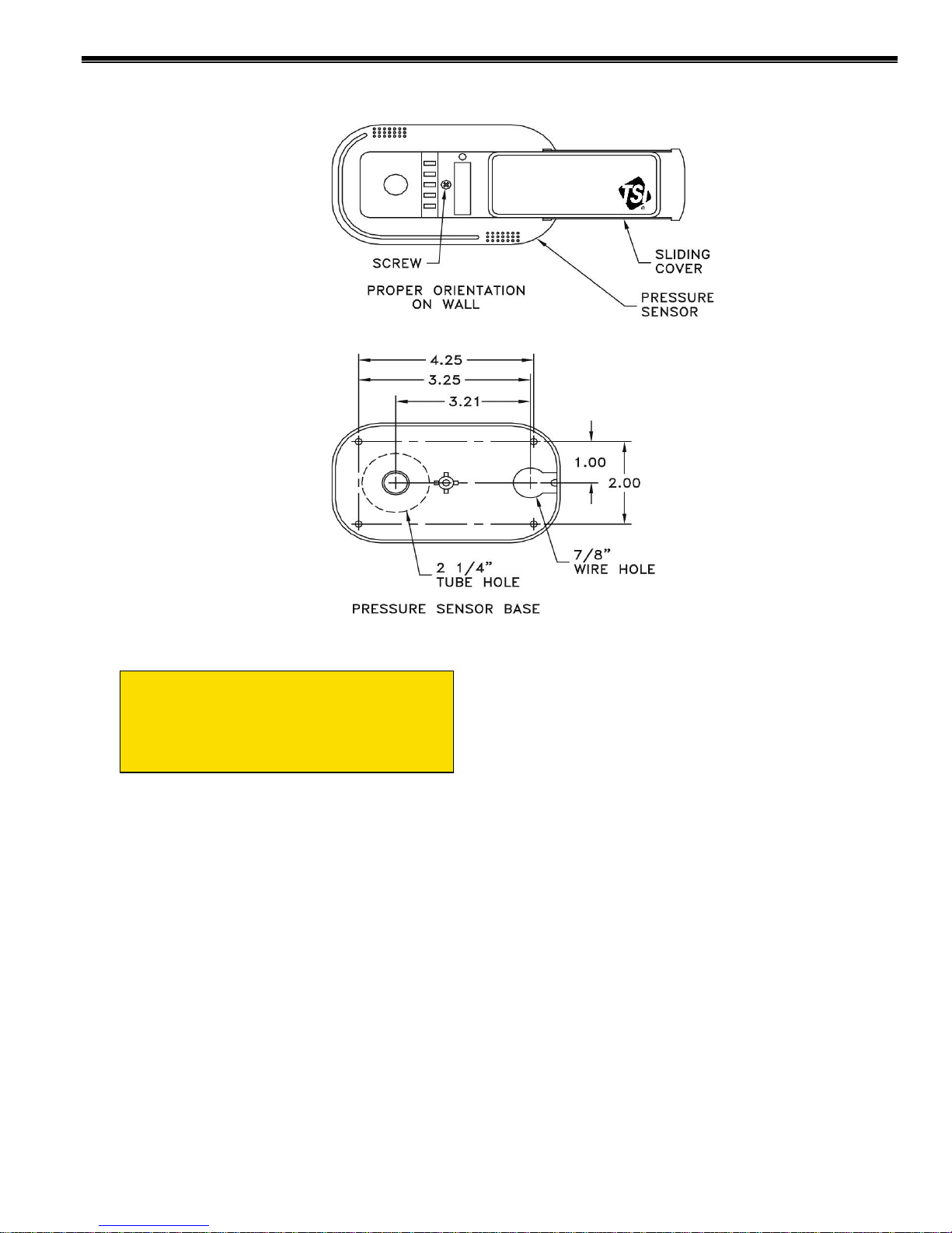
Figure 2: Pressure Sensor Orientation and Mounting Template
WARNING: 800326 pressure sensor must
be mounted through the wall between the
controlled space (laboratory) and
referenced space (hallway), exactly as
shown in Figure 2 and 3.
1. Determine pressure sensor location
(Figures 1, 2 and 3). Pressure sensor
typically mounts in the reference space, and
the dummy housing mounts in the
laboratory.
NOTE: Pressure sensor is not symmetrical.
If sensor is to be centered over hallway
door, measure one inch to the left of center
for 2¼-inch hole. Dummy sensor will be 2”
off center on other side of wall.
2. The pressure sensor must be orientated on
the wall as shown in Figure 2. Looking at
the mounted sensor, sensor hole is on the
left (2¼”) and wire hole is on the right.
3. Drill a 2¼-inch hole through each side of
the wall to accept the sensor tube.
4. Drill a 7/8 inch hole on the side of the wall
that the pressure sensor will be mounted.
This hole is for the six-conductor sensor
cable. Refer to Figure 2 for a hole mounting
pattern.
5. Slide sensor cover to right and remove
screw that holds the sensor base to the
pressure sensor (Figure 2). Remove
pressure sensor and store in a safe place.
6. From the side of the wall the sensor will be
mounted, slide the sensor tube through the
wall. Mark the tube where it is flush with
wall. Remove sensor tube and cut tube
1/8-inch shorter than flush marking.
NOTE: If 12” sensor tube is not long
enough add a 1” to 2” adapter and extend
with 2" OD tube. The base of the dummy
housing will need to be drilled out to
accommodate 2” tube. DO NOT extend
sensor tube with 1” tubing.
-2-
 Loading...