

TSI Incorporated DUSTTRAK DRX 8533, DUSTTRAK DRX 8533EP, DUSTTRAK DRX 8534 Operation And Service Manual
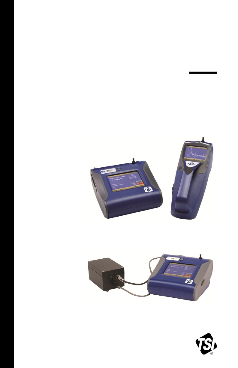
DUSTTRAK™ DRX
AEROSOL MONITOR
MODEL 8533/8534/8533EP
OPERATION AND SERVICE MANUAL
P/N 6001898, REVISION L
DECEMBER 2014
DustTrak DRX 8533 Desktop and 8534 Handheld
DustTrak DRX 8533EP Monitor


Copyright ©
TSI Incorporated / 2008–2014 / All rights reserved.
Address
TSI Incorporated / 500 Cardigan Road / Shoreview, MN 55126 / USA
Fax No.
(651) 490-3824
LIMITATION OF WARRANTY AND LIABILITY (effective April 2014)
(For country-specific terms and conditions outside of the USA, please visit www.tsi.com.)
Seller warrants the goods, excluding software sold hereunder, under normal use and
service as described in the operator's manual, shall be free from defects in workmanship
and material for twenty-four (24) months, or if less, the length of time specified in the
operator's manual, from the date of shipment to the customer. This warranty period is
inclusive of any statutory warranty. This limited warranty is subject to the following
exclusions and exceptions:
a. Hot-wire or hot-film sensors used with research anemometers, and certain other
components when indicated in specifications, are warranted for 90 days from the
date of shipment;
b. DustTrak internal pump for Models 8530 and 8533 is warranted for two (2) years or
4000 hours, whichever comes first;
c. DustTrak external pump for Models 8530EP and 8533EP is warranted for two (2)
years or 8760 hours, whichever comes first;
d. DustTrak internal pump for Models 8530 and 8533 is warranted for operation within
ambient temperatures between 5–45°C. Warranty is void when the internal pump is
operating outside of this temperature range;
e. Parts repaired or replaced as a result of repair services are warranted to be free from
defects in workmanship and material, under normal use, for 90 days from the date of
shipment;
f. Seller does not provide any warranty on finished goods manufactured by others or on
any fuses, batteries or other consumable materials. Only the original manufacturer's
warranty applies;
g. This warranty does not cover calibration requirements, and seller warrants only that
the instrument or product is properly calibrated at the time of its manufacture.
Instruments returned for calibration are not covered by this warranty;
h. This warranty is VOID if the instrument is opened by anyone other than a factory
authorized service center with the one exception where requirements set forth in the
manual allow an operator to replace consumables or perform recommended
cleaning;
i. This warranty is VOID if the product has been misused, neglected, subjected to
accidental or intentional damage, or is not properly installed, maintained, or cleaned
according to the requirements of the manual. Unless specifically authorized in a
separate writing by Seller, Seller makes no warranty with respect to, and shall have
no liability in connection with, goods which are incorporated into other products or
equipment, or which are modified by any person other than Seller.
The foregoing is IN LIEU OF all other warranties and is subject to the LIMITATIONS
stated herein. NO OTHER EXPRESS OR IMPLIED WARRANTY OF FITNESS FOR
PARTICULAR PURPOSE OR MERCHANTABILITY IS MADE. WITH RESPECT TO
SELLER’S BREACH OF THE IMPLIED WARRANTY AGAINST INFRINGEMENT, SAID
WARRANTY IS LIMITED TO CLAIMS OF DIRECT INFRINGEMENT AND EXCLUDES
CLAIMS OF CONTRIBUTORY OR INDUCED INFRINGEMENTS. BUYER’S
EXCLUSIVE REMEDY SHALL BE THE RETURN OF THE PURCHASE PRICE
DISCOUNTED FOR REASONABLE WEAR AND TEAR OR AT SELLER’S OPTION
REPLACEMENT OF THE GOODS WITH NON-INFRINGING GOODS.
TO THE EXTENT PERMITTED BY LAW, THE EXCLUSIVE REMEDY OF THE USER OR
BUYER, AND THE LIMIT OF SELLER'S LIABILITY FOR ANY AND ALL LOSSES,
i

INJURIES, OR DAMAGES CONCERNING THE GOODS (INCLUDING CLAIMS BASED
ON CONTRACT, NEGLIGENCE, TORT, STRICT LIABILITY OR OTHERWISE) SHALL
BE THE RETURN OF GOODS TO SELLER AND THE REFUND OF THE PURCHASE
PRICE, OR, AT THE OPTION OF SELLER, THE REPAIR OR REPLACEMENT OF THE
GOODS. IN THE CASE OF SOFTWARE, SELLER WILL REPAIR OR REPLACE
DEFECTIVE SOFTWARE OR IF UNABLE TO DO SO, WILL REFUND THE PURCHASE
PRICE OF THE SOFTWARE. IN NO EVENT SHALL SELLER BE LIABLE FOR LOST
PROFITS, BUSINESS INTERRUPTION, OR ANY SPECIAL, INDIRECT,
CONSEQUENTIAL OR INCIDENTAL DAMAGES. SELLER SHALL NOT BE
RESPONSIBLE FOR INSTALLATION, DISMANTLING OR REINSTALLATION COSTS
OR CHARGES. No Action, regardless of form, may be brought against Seller more than
12 months after a cause of action has accrued. The goods returned under warranty to
Seller's factory shall be at Buyer's risk of loss, and will be returned, if at all, at Seller's risk
of loss.
Buyer and all users are deemed to have accepted this LIMITATION OF WARRANTY AND
LIABILITY, which contains the complete and exclusive limited warranty of Seller. This
LIMITATION OF WARRANTY AND LIABILITY may not be amended, modified or its terms
waived, except by writing signed by an Officer of Seller.
Service Policy
Knowing that inoperative or defective instruments are as detrimental to TSI as they are
to our customers, our service policy is designed to give prompt attention to any
problems. If any malfunction is discovered, please contact your nearest sales office or
representative, or call TSI's Customer Service department at (800) 874-2811 (USA) or
(001 651) 490-2811 (International) or visit www.tsi.com.
ii

CONTENTS
SAFETY INFORMATION ............................................................................... V
Laser Safety ................................................................................................. v
Labels ......................................................................................................... vi
Description of Caution/Warning Symbols ................................................... vii
Caution ............................................................................................... vii
Warning .............................................................................................. vii
Caution and Warning Symbols ................................................................... vii
Reusing and Recycling .............................................................................. vii
CHAPTER 1 UNPACKING AND PARTS IDENTIFICATION ........................ 1
Unpacking the DustTrak DRX Aerosol Monitor ............................................. 1
Optional Accessories ............................................................................ 6
Parts Identification for the DustTrak DRX Desktop Aerosol Monitor
Model 8533 ............................................................................................... 7
Parts Identification for the DustTrak II Desktop Aerosol Monitor
Model 8533EP .......................................................................................... 8
External Pump Module (8533EP only) ......................................................... 8
Parts Identification for the DustTrak DRX Handheld Aerosol Monitor
Model 8534 ............................................................................................... 9
CHAPTER 2 SETTING UP .......................................................................... 11
Supplying Power to the DustTrak DRX Aerosol Monitor ............................ 11
Installing the Batteries in 8533/8533EP Desktop ................................ 11
Installing the Batteries in 8534 Handheld ............................................ 11
Connecting the External Pump to DustTrak Model 8533EP ............... 12
Using the AC Adapter to Run Instrument ............................................ 14
Battery Charging ................................................................................. 14
Inlet Cap.............................................................................................. 14
Instrument Setup ........................................................................................ 15
Connecting to the Computer ............................................................... 15
Installing TrakPro™ Data Analysis Software....................................... 15
Connecting Analog/Alarm Output ........................................................ 16
Wiring the Analog Output ........................................................................... 16
Wiring the Alarm ......................................................................................... 17
CHAPTER 3 OPERATION .......................................................................... 19
Getting Started ........................................................................................... 19
For Model DustTrak 8533EP only .............................................................. 19
Setup Menu ................................................................................................ 22
Zero Cal .............................................................................................. 23
Flow Cal .............................................................................................. 24
User Cal .............................................................................................. 25
Alarm .................................................................................................. 31
Analog ................................................................................................. 34
Settings ............................................................................................... 35
Run Mode ........................................................................................... 37
Survey Mode ....................................................................................... 38
Manual Mode ................................ ...................................................... 39
Log Mode (1–5) ................................................................................... 40
iii

Taking Mass Concentration Measurements ............................................... 41
Screen Regions .................................................................................. 42
Stats ................................................................................................... 43
Graphing ............................................................................................. 45
Viewing Data .............................................................................................. 47
Title Bar ..................................................................................................... 48
CHAPTER 4 MAINTENANCE ..................................................................... 49
Maintenance Schedule .............................................................................. 49
Zeroing Instrument ..................................................................................... 50
Cleaning the Inlet ....................................................................................... 50
Cleaning 2.5 µm Calibration Impactor ........................................................ 51
Replacing the Internal Filters ..................................................................... 52
Replacing the Filters in the External Pump Module ................................... 55
Storage Precautions .................................................................................. 56
CHAPTER 5 TROUBLESHOOTING ........................................................... 57
APPENDIX A SPECIFICATIONS .............................................................. 63
APPENDIX B DRX ADVANCED CALIBRATION ...................................... 65
Option 1: Serial Gravimetric Calibration ..................................................... 65
Step 1: PCF Calibration ...................................................................... 65
Step 2: SCF Calibration ...................................................................... 65
Option 2: Parallel Gravimetric Calibration .................................................. 66
APPENDIX C ZERO MODULE .................................................................. 69
INDEX ........................................................................................................... 71
These Application Notes can also be found on TSI’s web site:
http://www.tsi.com
EXPMN-002 DustTrak DRX Theory of Operation.pdf
EXPMN-004 DRX-TEOM Comparison.pdf
EXPMN-005 DustTrak DRX Standard and Advance Calibration.pdf
iv
Safety Information
I M P O R T A N T
There are no user serviceable parts inside the instrument. Refer all repair
and maintenance to a qualified factory-authorized technician. All
maintenance and repair information in this manual is included for use by a
qualified factory-authorized technician.
W A R N I N G
The use of controls, adjustments, or procedures other
than those specified in this manual may result in exposure
to hazardous optical radiation.
W A R N I N G
There are no user-serviceable parts inside this
instrument. The instrument should only be opened by TSI
or a TSI approved service technician.
W A R N I N G
If the DustTrak monitor is used in a manner not specified
by the manufacturer, the protection provided by the
equipment may be impaired.
Laser Safety
The Model 8533/8534 DustTrak DRX monitor is a Class I laser- based
instrument
During normal operation, you will not be exposed to laser radiation
Precaution should be taken to avoid exposure to hazardous radiation in
the form of intense, focused, visible light
Exposure to this light may cause blindness
Take these precautions:
DO NOT remove any parts from the DustTrak DRX monitor unless you
are specifically told to do so in this manual
DO NOT remove the housing or covers. There are no serviceable
components inside the housing
When operated according to the manufacturer’s instruction, this device is a
Class I laser product as defined by U.S. Department of Health and Human
Services standards under the Radiation Control for Health and Safety Act of
1968. A certification and identification label like the one shown below is
affixed to each instrument.
v
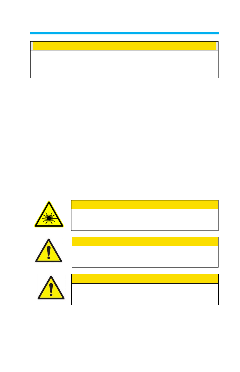
Labels
1. Serial Number Label
(bottom)
2. Laser Radiation Label
(internal)
DANGER!
VISIBLE LASER RADIATION WHEN
OPEN. AVOID DIRECT EXPOSURE
TO BEAM
WARNING: NO USER SERVICABLE
PARTS INSIDE. REFER SERVICING
TO QUALIFIED PERSONNEL
3. Battery label
or
4. European symbol for nondisposable item. Item must
be recycled.
Advisory labels and identification labels are attached to the instrument.
vi

Description of Caution/Warning Symbols
C a u t i o n
Failure to follow the procedures prescribed in this
manual might result in irreparable equipment damage.
Important information about the operation and
maintenance of this instrument is included in this
manual.
W A R N I N G
Warning means that unsafe use of the instrument could
result in serious injury to you or cause damage to the
instrument. Follow the procedures prescribed.
Warns that the instrument contains a laser and that
important information about its safe operation and
maintenance is included in the manual.
Warns that the instrument is susceptible to electro-static
discharge (ESD) and ESD protection should be followed
to avoid damage.
Indicates the connector is connected to earth ground and
cabinet ground.
Appropriate caution/warning statements are used throughout the manual and
on the instrument that require you to take cautionary measures when working
with the instrument.
Caution
Warning
Caution and Warning Symbols
The following symbols may accompany cautions and warnings to indicate the
nature and consequences of hazards:
Reusing and Recycling
As part of TSI Incorporated’s effort to have a minimal
negative impact on the communities in which its products
are manufactured and used:
Do not dispose of used batteries in the trash.
Follow local environmental requirements for
battery recycling.
If instrument becomes obsolete, return to TSI for
disassembly and recycling.
vii

(This page intentionally left blank)
viii
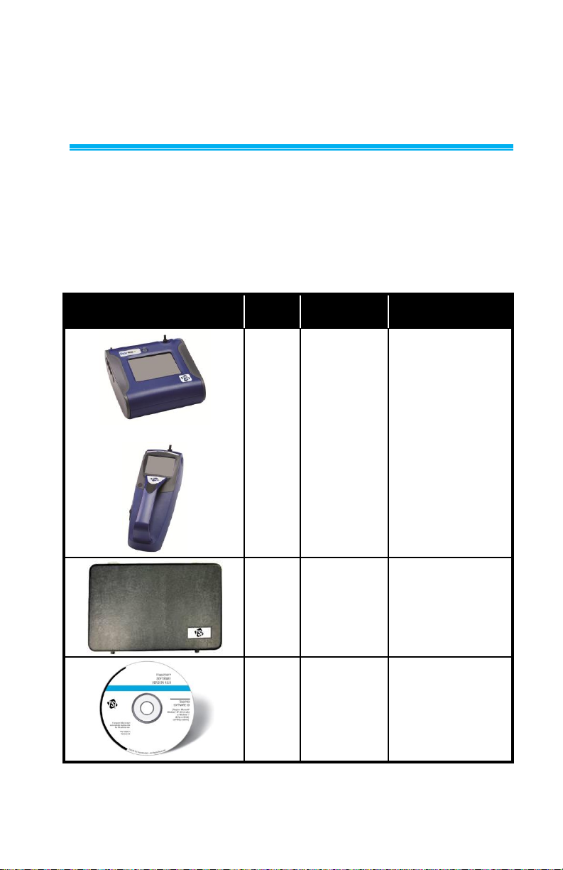
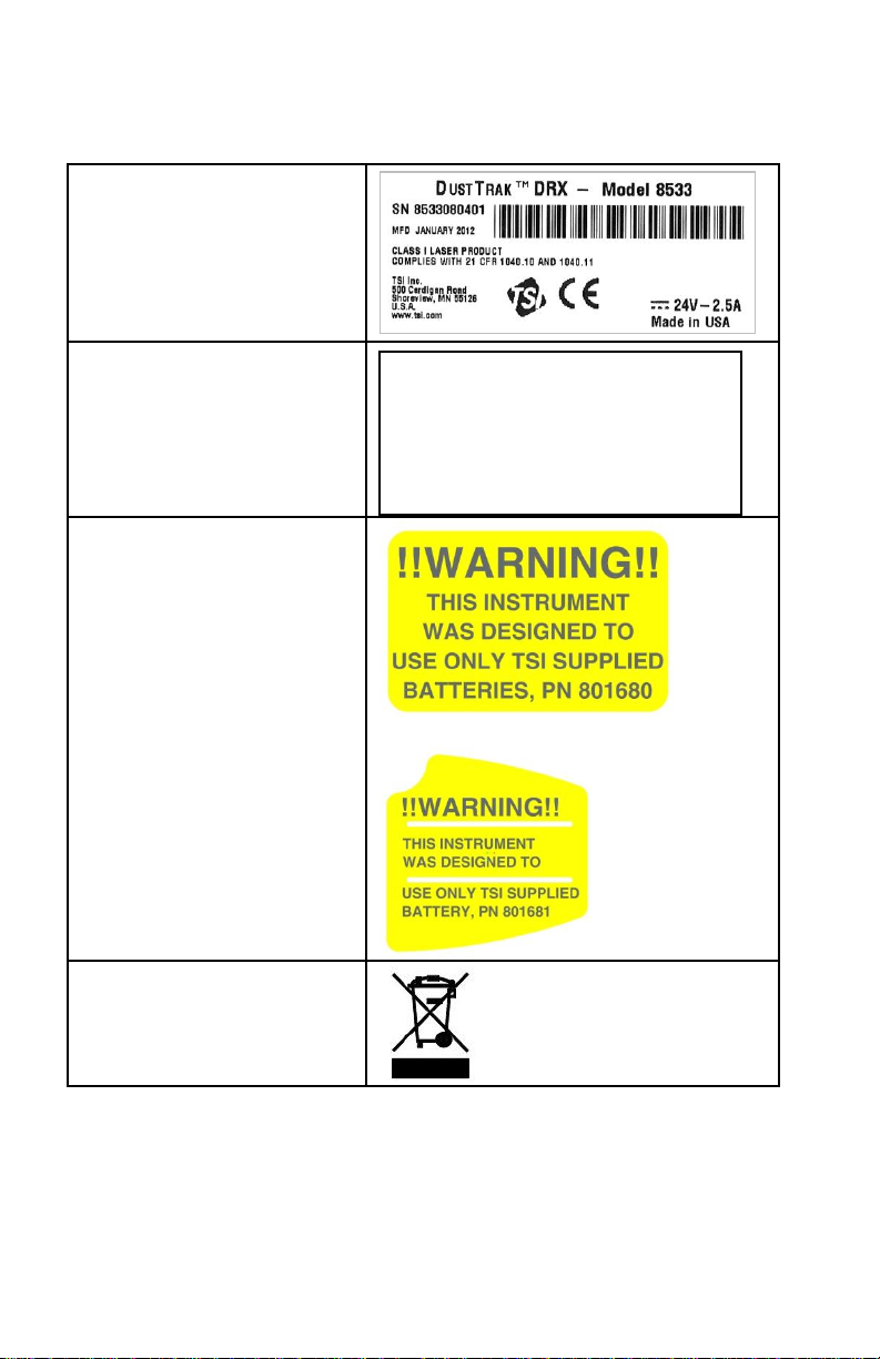
Item
Qty
Part
Number
Description
or
1
8533
8534
Desktop DRX
Handheld DRX
1
801670
801669
Desktop DRX
Carrying Case
Handheld DRX
Carrying Case
1
1090014
Data Analysis
Software CDROM
Chapter 1
Unpacking and Parts Identification
Carefully unpack the Model 8533/34 DustTrak DRX Aerosol Monitor from the
shipping container. Use the tables and illustrations below to make certain that
there are no missing components. Contact TSI immediately if anything is
missing or damaged.
Unpacking the DustTrak DRX Aerosol Monitor
Compare all the components you received with those listed in the table
below. If any parts are missing, contact TSI.
1
2
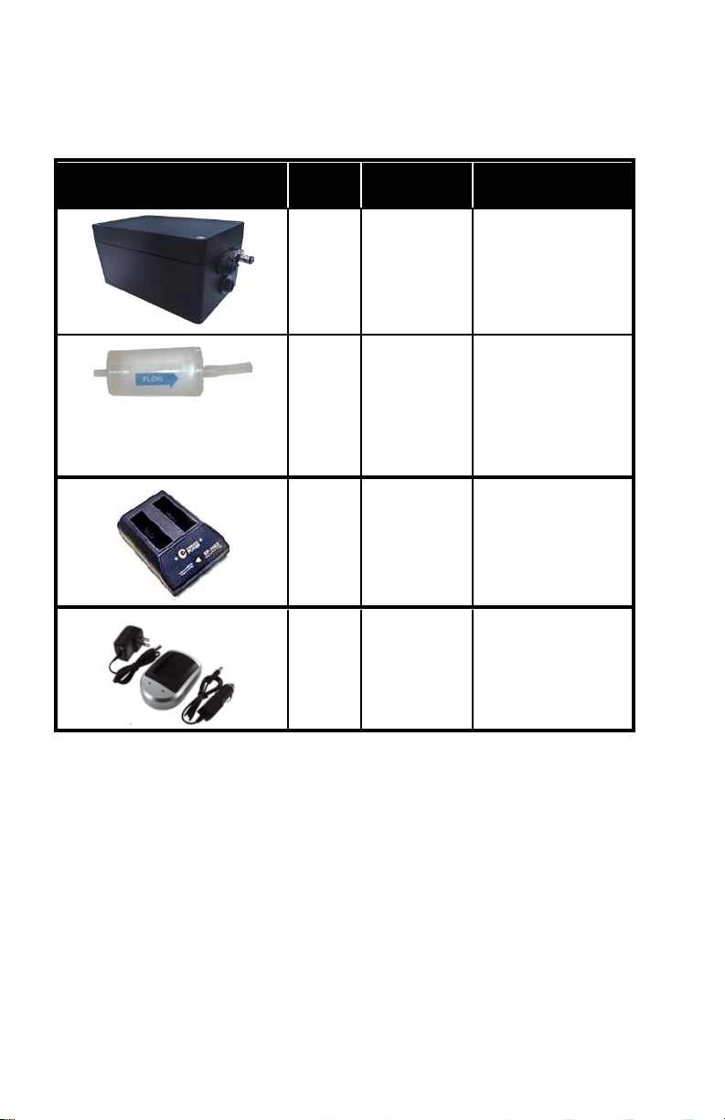
Item
Qty
Part
Number
Description
1
800663
Zero Filter
or
1
801680
801681
6600 mAH
Lithium Ion
Rechargeable
Battery (Desktop)
Rechargeable
lithium ion battery
(Handheld)
1
1303740
USB cable
1
801652
Analog/alarm
output cable
(Desktop models
only)
1
6001898
Operation and
Service Manual
1
N/A
Calibration
Certificate
Chapter 1
3
Item
Qty
Part
Number
Description
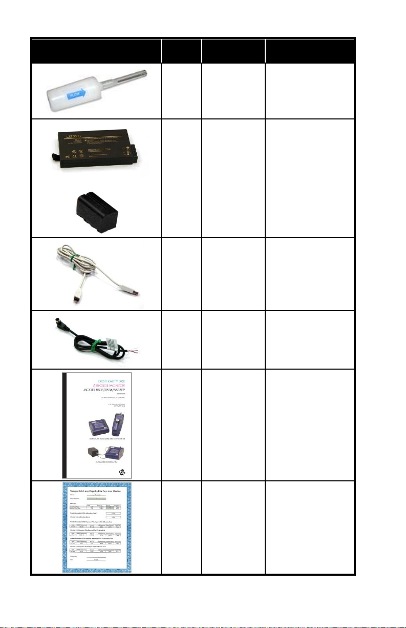
1
801688
Conductive
Tubing
1
801668
Filter removal tool
(Spanner Driver)
4
2
1
801673
Spare Internal
Filter Elements
Desktop Model
Only
37-mm filter
includes:
Filter body top
Filter body bottom
Mesh Screen
Comes with
37-mm cartridge
opening tool.
8
801666
Spare Internal
Filters
Handheld Model
Only
1
801671
Calibration
Impactor Kit
PM
2.5
which
includes:
Impactor top
Impactor bottom
Impaction plate
Unpacking and Parts Identification
4
Item
Qty
Part
Number
Description
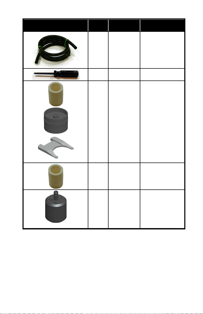
1
801692
801694
Power Supply –
Desktop
Power Supply Handheld
2
N/A
Stylus
When shipped,
one stylus will be
in the accessory
bag, the second
stylus is attached
to instrument.
1
3012094
Screwdriver, dual
ended. (For
Handheld Models
only)
1
801674
Impactor Oil
2
801698
Inlet cap
When shipped,
one inlet will be in
the accessory
bag, the second
inlet is attached to
instrument.
1
801675
External Pump Kit
for 8533EP only
Chapter 1
5
Item
Qty
Part
Number
Description
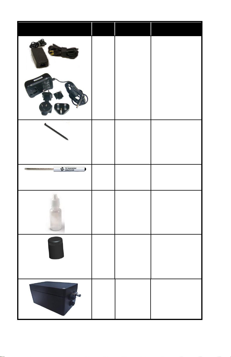
1
801797
External Pump
Power Cable (to
DustTrak monitor)
for 8533EP only
1
801798
External Pump
Flow Tube (to
DustTrak monitor)
for 8533EP only
1
Exhaust Adapter,
DustTrak monitor
for 8533EP only
Unpacking and Parts Identification
6
Optional Accessories
Accessories
Qty
Part
Number
Description
1
801675
External Pump Kit
for 8533EP only
2
801795
DustTrak II/DRX
External Pump
Service Kit for
8533EP only.
Contains two
filters for External
Pump.
1
801685
Battery Charger,
2-Bay, Battery
801680 for
Desktop DustTrak
monitor
1
801686
Battery Charger,
Battery 801681
for Handheld
DustTrak monitor
The following photos and table list optional accessories. If you ordered
optional accessories, make certain they have been received and are in
working order.
Chapter 1
7
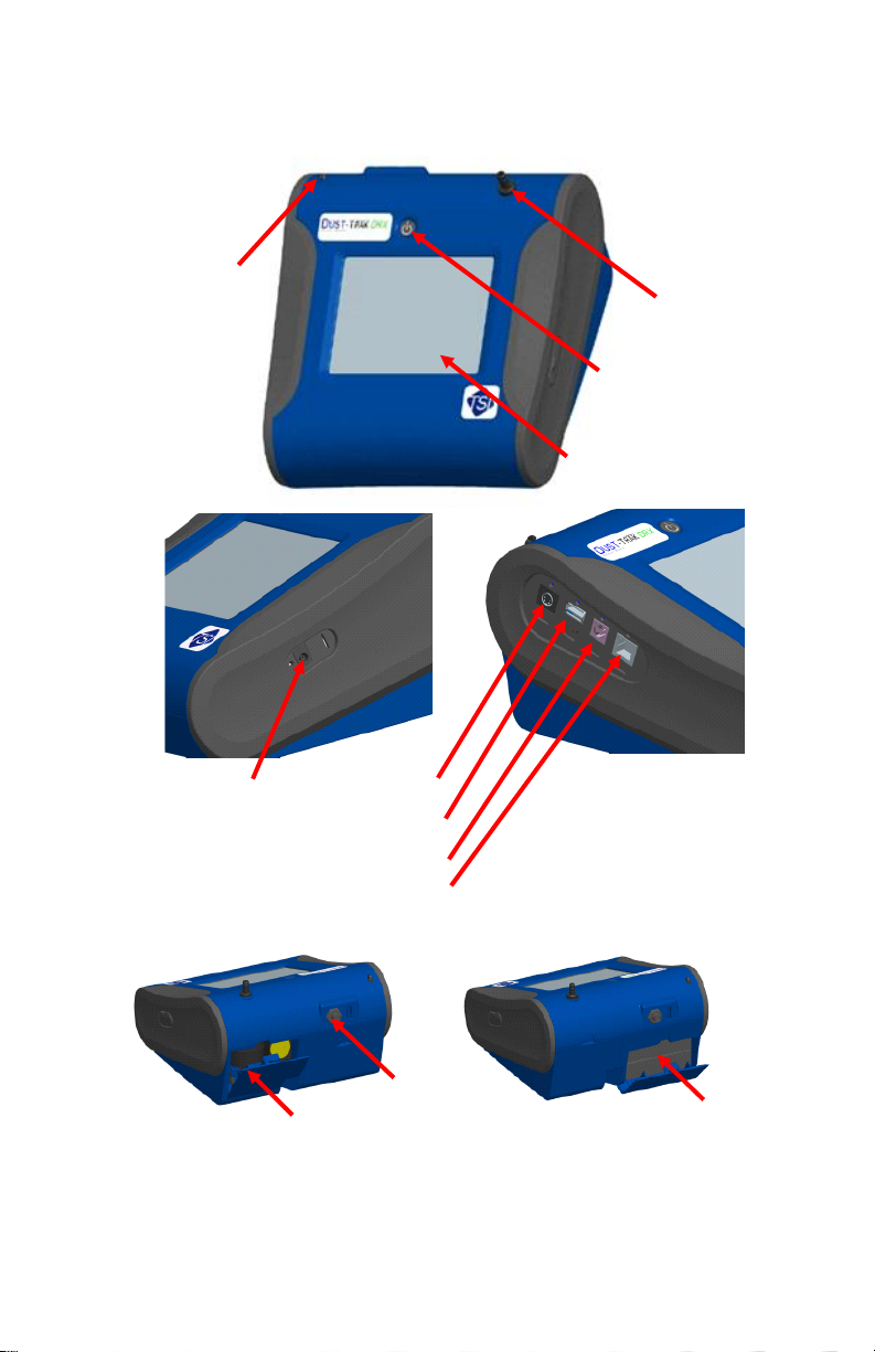
Parts Identification for the DustTrak DRX Desktop
Touchscreen
On/Off
Inlet
Stylus
Power
Analog/Alarm
Output
USB Host
USB Device
Ethernet
Filter Access
Zero Module
Connector
Battery Access
Aerosol Monitor Model 8533
Figure 1-1: Features on Desktop Model
Unpacking and Parts Identification
8
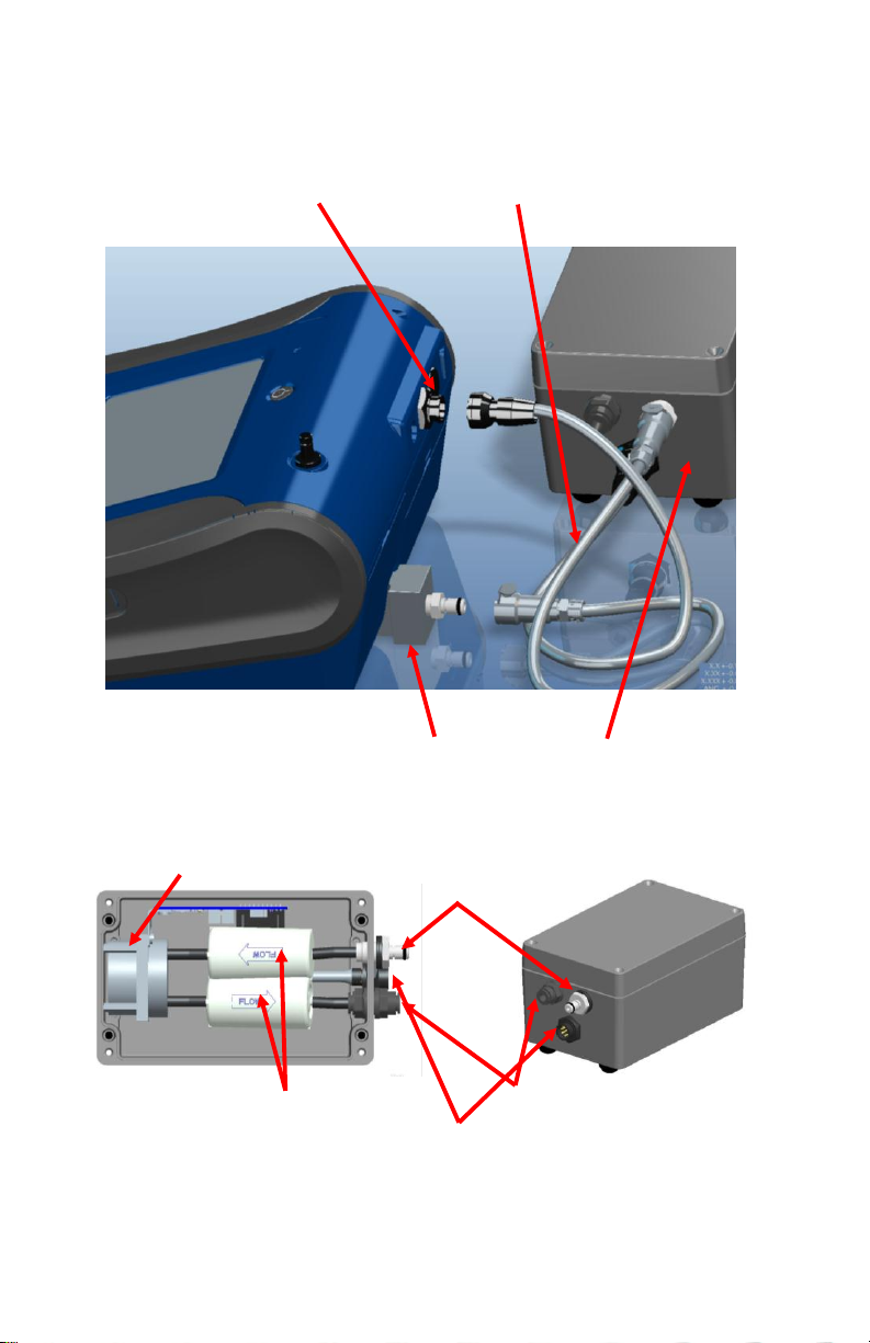
Parts Identification for the DustTrak II Desktop
Exhaust Adapter External Pump
External Pump
Power Connection
External Pump
Flow Tubing
Pump Suction End
Pump Exhaust End
Pump Power Connection
User Replaceable HEPA Filters
Pump
Aerosol Monitor Model 8533EP
External Pump Module (8533EP only)
Figure 1-2: Features on Desktop Model 8533EP
Chapter 1

9
Parts Identification for the DustTrak DRX Handheld
On/Off
Inlet
Stylus
Touchscreen
Port Cover
Power
USB Device
USB Host
Filter Access
Battery Access
(Screw Lockdown)
Aerosol Monitor Model 8534
Figure 1-3: Features on Handheld Model
Unpacking and Parts Identification

10
(This page intentionally left blank)
Chapter 1
W A R N I N G
The instrument has been design to be used with batteries
supplied by TSI. Do not use a substitute.
Disposing of old batteries must be recycled in accordance
with the local environmental regulations.
W A R N I N G
Do not use non-rechargeable batteries in this instrument.
Fire, explosions, or other hazards may result.
Chapter 2
Setting Up
Supplying Power to the DustTrak DRX Aerosol Monitor
The Model 8533 and 8534 DustTrak DRX Aerosol Monitor must be powered
by either batteries or using the external AC adapter.
Installing the Batteries in 8533/8533EP Desktop
Remove the battery cover and slide one or two batteries into the battery slots.
A single battery can be put into either slot. Orient the batteries with the label
side facing up (see Figure 2-1).
Figure 2-1: Batteries into Desktop Unit
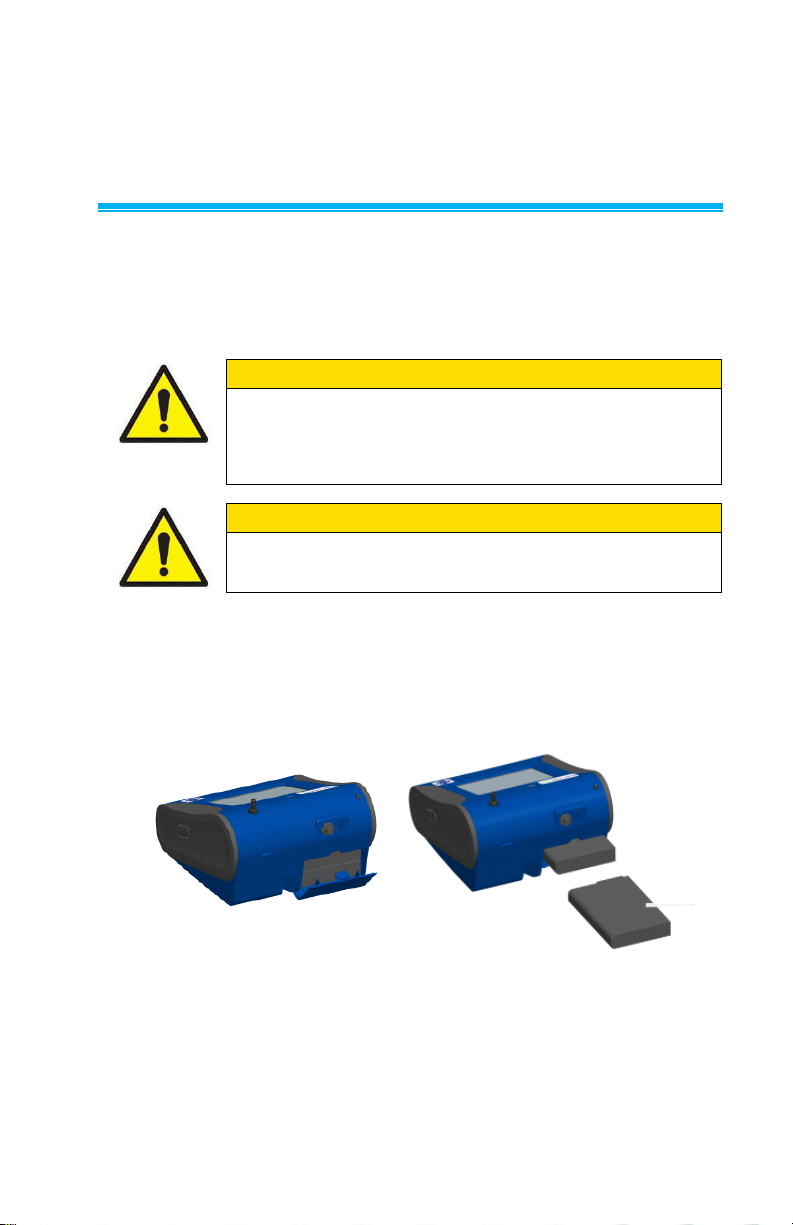
Installing the Batteries in 8534 Handheld
Remove the battery cover by loosening captured screw on the bottom of the
unit. Orient battery with brass connectors facing forward. Insert battery into
cavity and slide forward to engage into pins. Replace the battery cover and
secure by tightening screw (see Figure 2-2).
11
12
Figure 2-2: Batteries into Handheld Unit
W A R N I N G
Turn the DustTrak monitor OFF before connecting the
external pump. Turn the DustTrak monitor ON only after
connecting the External Module.
Connecting the External Pump to DustTrak Model 8533EP
The Model 8533EP is a Desktop DustTrak monitor with an external pump.
This DustTrak monitor has no internal pump and will not work with any other
external pump other than the one provided by TSI (p/n 801675). The Model
8533EP is intended for applications where the DustTrak monitor is operated
continuously over extended periods (several days to months) under wide
temperature fluctuations (0 to 50°C). The external pump is designed to be
more robust for 24/7 operation of the DustTrak monitor and is warranted to
operate continuously for one full year or 8760 hours. The Model 8533EP is
ideal for fugitive dust monitoring.
The pump and the DustTrak monitor come separately and require assembly.
Follow the steps below to connect the pump with the Model 8533EP DustTrak
monitor.
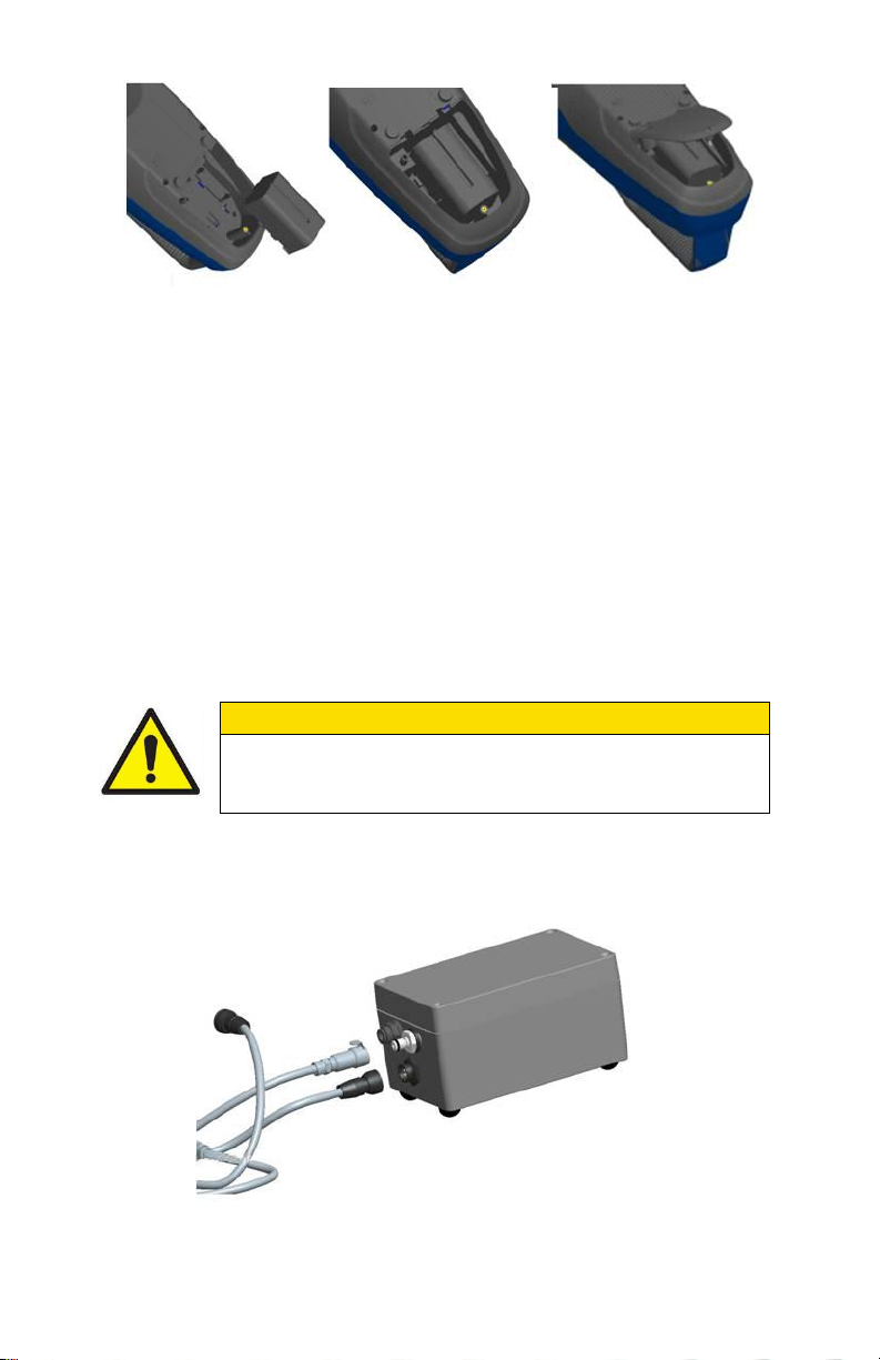
1. Connect the pump end of the quick connect to the pump module (see
Figure 2-3).
Figure 2-3: Connect Pump End of Quick Connect to Pump Module
Chapter 2
13
2. Likewise, plug one end of the power connector to the pump module as
W A R N I N G
The Pump module design does not allow for installation
outdoors without any protection from the elements. Always
operate it within an enclosure.
shown above. Turn the power connector until it clicks and locks in place.
This prevents the connector from disconnecting due to vibration or
movement.
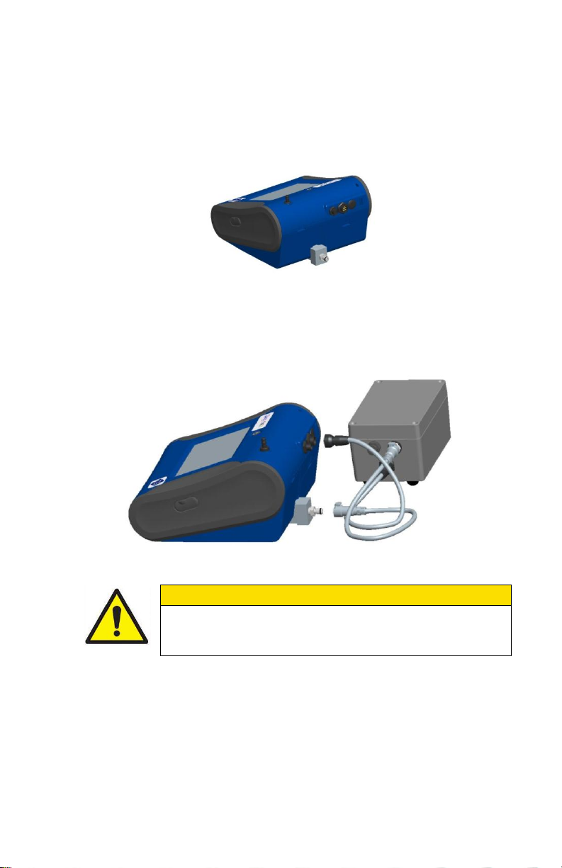
3. Connect the exhaust adapter to the exhaust of the DustTrak monitor (see
Figure 2-4).
Figure 2-4: Connect Exhaust Adapter to Exhaust of DustTrak Monitor
4. Connect the other end of the flow tubing to the exhaust adapter of the
DustTrak monitor.
5. Connect the other end of the power connector to the DustTrak monitor
(see Figure 2-5).
Figure 2-5: Connect Power Connector to DustTrak Monitor
The DustTrak external pump module does not require an A/C adapter. It is
always powered off the DustTrak monitor.
Setting-Up

14
Notes
1. The power connector and the flow quick connect “click” when
securely connected. The power connector must be rotated
clockwise past the locking pin.
2. Do not hot-plug the External Pump Module when the
DustTrak monitor is turned ON. Always connect the External
Pump module first and then turn the DustTrak monitor ON.
3. TSI recommends that the DustTrak monitor with the external
pump be operated in the Model 8535 Environmental
Enclosure.
4. TSI recommends that the pump module be operated when
mounted on its feet and avoid operating at other orientations
as much as possible.
5. Pump module and the DustTrak monitor should be at the
same electrical potential.
6. The additional port on the external pump module is where the
pump exhausts the flow. For applications where the DustTrak
monitor is sampling from a chamber or a duct at pressures
significantly different from the ambient, TSI recommends
plumbing the exhaust of the external pump back in to the
chamber/duct.
Using the AC Adapter to Run Instrument
W A R N I N G
When Charging Battery the ambient temp must not
exceed 42°C.
The AC adapter allows you to power the DustTrak monitor from an AC wall
outlet. When using the AC adapter, the batteries (if installed) are bypassed.
Battery Charging
This instrument will charge the Lithium Ion battery packs. Insert the batteries
into the battery compartment, plug the instrument into AC power, and turn the
instrument on. Batteries will charge only when the instrument is on and in
stand-by mode. Batteries will not charge if the instrument is turned off or is
actively taken measurements. Charging will stop when the batteries are fully
charged.
Inlet Cap
When using the DustTrak monitor to sample environmental air, the inlet cap
should be put over the instrument. This cap will keep large objects from
dropping into and plugging the inlet. The cap will also keep direct light from
shinning into the chamber and skewing the results.
The inlet cap can simply be pressed onto the instruments inlet.
Chapter 2

15
Note
To use TrakPro software with the DustTrak Aerosol Monitor, the
PC must be running Microsoft Windows® and the computer must
have an available Universal Serial Bus (USB) port.
Note
If the software does not start automatically after a few minutes,
manually run the program listed on the label of the CD using the
Run command on the Windows Start Menu.
Figure 2-6: Putting on Inlet Cap
Instrument Setup
The DustTrak DRX monitor can be connected to a computer to download
data and upload sampling programs.
Connecting to the Computer
Connect the USB host port of a Microsoft® Windows®-based computer to the
USB device port on the side of the DustTrak monitor.
Installing TrakPro™ Data Analysis Software
TrakPro software can preprogram the DustTrak monitor, download data, view
and create raw data and statistical reports, create graphs, and combine
graphs with data from other TSI instruments that use TrakPro software. The
following sections describe how to install the software and set up the
computer.
1. Insert the TrakPro Data Analysis Software CD into the CD-ROM drive.
The install screen starts automatically.
2. Follow the directions to install TrakPro software.
®
Microsoft and Windows are registered trademarks of Microsoft Corporation.
Setting-Up
16
TrakPro software contains a comprehensive installation guide. TSI
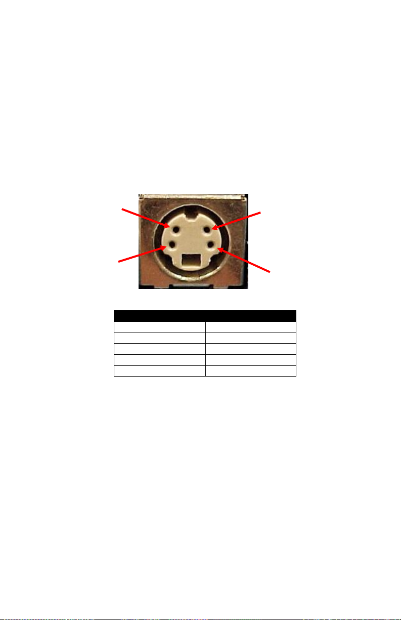
Cable Wiring Diagram
Brown Wire
Analog Ground
Orange Wire
Analog Out
Red Wire
Alarm (+)
White Wire
Alarm (-)
Black Wire
Shield
Alarm Positive
(+)
Alarm Ground (–)
Analog Output (+)
Analog Ground
(–)
recommends printing out this guide prior to starting the TrakPro software
installation on your computer, so it may be consulted during the installation.
The TrakPro Software manual is located in the “Help” file in TrakPro software.
There is no separately printed TrakPro Data Analysis software manual.
Connecting Analog/Alarm Output
The Analog/Alarm Output Cable plugs into the alarm connection on the side
of the instrument. This feature is on the desktop models (II, II HC and
8533) only.
The cable contains a 4-pin, mini-DIN connector. The pin-outs for the
connector and the wiring for the cable are shown below.
4-pin miniDIN connector
Figure 2-7: Cable Wiring Diagram
Wiring the Analog Output
Output voltage: 0 to 5 VDC. With a maximum output of 15 mA.
Output Current 4 mA to 20 mA with a maximum load impendence of
250 ohms.
Correct polarity must be observed (see pin-outs above).
The output cable supplied by TSI (part no. 801652) is labeled with the pin-out
wiring diagram. Additional equipment may be needed for making connections
to the system that TSI does not supply. It is your responsibility to specify and
supply all additional equipment.
Chapter 2
 Loading...