

Page 1
CERTIFIER® FA PLUS
TEST SYSTEM
OPERATOR’S MANUAL
P/N 1980560, REVISION J
FEBRUARY 2016
Page 2

Page 3

CERTIFIER® FA PLUS
TEST SYSTEM
OPERATOR’S MANUAL
P/N 1980560, REVISION J
FEBRUARY 2016
U.S. & INTERNATIONAL TSI Instruments Ltd. (UK)
Sales and Customer Service: Sales and Customer Service:
(800) 874-2811 / +1(651) 490-2811 +44 (0) 1494 459200
Fax: Fax:
+1(651) 490-3824 +44 (0) 1494 459700
Page 4

Page 5

Copyright TSI Incorporated / 2010-2016 / All rights reserved.
Address
TSI Incorporated / 500 Cardigan Road / Shoreview, MN 55126 / USA
Fax No.
(651) 490-3824
Caution
TSI flowmeters are not medical devices under FDA 510(k) and in no situation should be
used for human measurements.
LIMITATION OF WARRANTY AND LIABILITY (effective February 2015)
(For country-specific terms and conditions outside of the USA, please visit www.tsi.com.)
Seller warrants the goods, excluding software, sold hereunder, under normal use and service as described in the
operator's manual, to be free from defects in workmanship and material for 12 months, or if less, the length of
time specified in the operator's manual, from the date of shipment to the customer. This warranty period is
inclusive of any statutory warranty. This limited warranty is subject to the following exclusions and exceptions:
a. Hot-wire or hot-film sensors used with research anemometers, and certain other components when indicated
in specifications, are warranted for 90 days from the date of shipment;
b. Pumps are warranted for hours of operation as set forth in product or operator’s manuals;
c. Parts repaired or replaced as a result of repair services are warranted to be free from defects in workmanship
and material, under normal use, for 90 days from the date of shipment;
d. Seller does not provide any warranty on finished goods manufactured by others or on any fuses, batteries or
other consumable materials. Only the original manufacturer's warranty applies;
e. This warranty does not cover calibration requirements, and seller warrants only that the instrument or
product is properly calibrated at the time of its manufacture. Instruments returned for calibration are not
covered by this warranty;
f. This warranty is VOID if the instrument is opened by anyone other than a factory authorized service center
with the one exception where requirements set forth in the manual allow an operator to replace
consumables or perform recommended cleaning;
g. This warranty is VOID if the product has been misused, neglected, subjected to accidental or intentional
damage, or is not properly installed, maintained, or cleaned according to the requirements of the manual.
Unless specifically authorized in a separate writing by Seller, Seller makes no warranty with respect to, and
shall have no liability in connection with, goods which are incorporated into other products or equipment, or
which are modified by any person other than Seller.
The foregoing is IN LIEU OF all other warranties and is subject to the LIMITATIONS stated herein. NO OTHER
EXPRESS OR IMPLIED WARRANTY OF FITNESS FOR PARTICULAR PURPOSE OR MERCHANTABILITY
IS MADE. WITH RESPECT TO SELLER’S BREACH OF THE IMPLIED WARRANTY AGAINST
INFRINGEMENT, SAID WARRANTY IS LIMITED TO CLAIMS OF DIRECT INFRINGEMENT AND EXCLUDES
CLAIMS OF CONTRIBUTORY OR INDUCED INFRINGEMENTS. BUYER’S EXCLUSIVE REMEDY SHALL BE
THE RETURN OF THE PURCHASE PRICE DISCOUNTED FOR REASONABLE WEAR AND TEAR OR AT
SELLER’S OPTION REPLACEMENT OF THE GOODS WITH NON-INFRINGING GOODS.
TO THE EXTENT PERMITTED BY LAW, THE EXCLUSIVE REMEDY OF THE USER OR BUYER, AND THE
LIMIT OF SELLER'S LIABILITY FOR ANY AND ALL LOSSES, INJURIES, OR DAMAGES CONCERNING
THE GOODS (INCLUDING CLAIMS BASED ON CONTRACT, NEGLIGENCE, TORT, STRICT LIABILITY OR
OTHERWISE) SHALL BE THE RETURN OF GOODS TO SELLER AND THE REFUND OF THE PURCHASE
PRICE, OR, AT THE OPTION OF SELLER, THE REPAIR OR REPLACEMENT OF THE GOODS. IN THE
i
Page 6

CASE OF SOFTWARE, SELLER WILL REPAIR OR REPLACE DEFECTIVE SOFTWARE OR IF UNABLE TO
DO SO, WILL REFUND THE PURCHASE PRICE OF THE SOFTWARE. IN NO EVENT SHALL SELLER BE
LIABLE FOR LOST PROFITS, BUSINESS INTERRUPTION, OR ANY SPECIAL, INDIRECT,
CONSEQUENTIAL OR INCIDENTAL DAMAGES. SELLER SHALL NOT BE RESPONSIBLE FOR
INSTALLATION, DISMANTLING OR REINSTALLATION COSTS OR CHARGES. No Action, regardless of
form, may be brought against Seller more than 12 months after a cause of action has accrued. The goods
returned under warranty to Seller's factory shall be at Buyer's risk of loss, and will be returned, if at all, at
Seller's risk of loss.
Buyer and all users are deemed to have accepted this LIMITATION OF WARRANTY AND LIABILITY, which
contains the complete and exclusive limited warranty of Seller. This LIMITATION OF WARRANTY AND
LIABILITY may not be amended, modified or its terms waived, except by writing signed by an Officer of Seller.
Service Policy
Knowing that inoperative or defective instruments are as detrimental to TSI as they are to our customers, our
service policy is designed to give prompt attention to any problems. If any malfunction is discovered, please
contact your nearest sales office or representative, or call TSI's Customer Service department at (800) 8742811 / (1) 651 490-2811 (USA and International) or TSI Instruments in UK at: +44 (0) 1494 4 59200.
Trademarks
Certifier® is a registered trademark of TSI Incorporated.
ii Certifier® FA Plus Test System
Page 7

CONTENTS
1 INTRODUCTION ....................................................................................................... 1
1.1 Parts List ......................................................................................................... 2
1.2 Glossary .......................................................................................................... 6
1.2.1 Symbols on Display ............................................................................ 6
2 SETUP AND OPERATION ..................................................................................... 11
2.1 Keypad Functions ......................................................................................... 15
2.2 Power up ....................................................................................................... 16
2.3 Display Navigation ........................................................................................ 17
2.3.1 Measurement Selection .................................................................... 20
2.3.2 Graph Measurement Selection ......................................................... 21
2.3.3 Available Measurement Parameters ................................................. 22
2.3.4 Gas Conditions Selection Box .......................................................... 24
2.3.5 Averaging Setup Menu ..................................................................... 25
2.3.6 Breath Trigger Types ........................................................................ 26
2.3.7 Flow Triggering ................................................................................. 27
2.3.8 Saving/Loading Configurations ......................................................... 28
2.3.9 Print/Save Button .............................................................................. 29
2.3.9.1 Waveform Logging ..................................................................... 30
2.3.9.2 Continuous Logging ................................................................... 31
2.3.10 Setup Key ......................................................................................... 32
2.3.10.1 Advanced Features .................................................................... 33
2.3.10.1.1 Configuration Import/Export .................................................. 33
2.3.10.1.2 Format Settings ..................................................................... 34
2.4 Required Pre-test Calibrations ..................................................................... 35
2.4.1 Low Flow Module .............................................................................. 35
2.4.1.1 None required ............................................................................ 35
2.4.2 High Flow Module ............................................................................. 35
2.4.2.1 Zeroing the Flow Direction Sensor ............................................ 35
2.4.2.2 Low-Pressure and High-Pressure Transducer Zeroing ............. 35
2.4.2.3 Oxygen Sensor Calibration ........................................................ 36
3 TROUBLESHOOTING ........................................................................................... 37
iii
Page 8

4 MAINTENANCE ...................................................................................................... 41
4.1 Recharging the Batteries (as required) ......................................................... 41
4.2 Replacing the Oxygen Sensor ...................................................................... 41
4.3 Cleaning (as required) ................................................................................... 41
4.4 Factory Calibration (recommended yearly) ................................................... 42
4.5 Return Procedure .......................................................................................... 42
5 SPECIFICATIONS ................................................................................................... 43
5.1 Physical ......................................................................................................... 43
5.2 Environmental ............................................................................................... 43
5.3 Power ............................................................................................................ 43
5.4 Data Transfer and Storage ............................................................................ 44
5.5 Test Measurements (See notes at end of section. See Table 3 for
symbol definitions.) ....................................................................................... 44
5.6 Calibration Recommendations ...................................................................... 47
5.7 Compliance and Approvals ........................................................................... 47
APPENDIX A DATA FILE FORMATS ......................................................................... 49
LIST OF FIGURES
Figure 1. Certifier® FA Test System High Flow Standard Kit (4080) ............................... 2
Figure 2. Certifier® FA Test System Low Flow Module Kit (4082) ................................... 4
Figure 3. Certifier® FA Test System Oxygen Sensor Kit (4073) ...................................... 4
Figure 4. Certifier® FA Test System Extra Battery and Charger Kit (1208061) ............... 5
Figure 5. Interface Module ............................................................................................... 7
Figure 6. Back of Interface Module .................................................................................. 8
Figure 7. High Flow Module (arrow on module indicates positive flow direction) ........... 9
Figure 8. Low Flow Module .............................................................................................. 9
Figure 9. Oxygen Sensor Kit .......................................................................................... 10
Figure 10. Connecting the Interface Module to a Flow Module ..................................... 11
Figure 11. Installing a Flow Module into the Circuit for Measuring Bi-directional
Flow (flow direction Arrow should be towards test lung) .............................. 12
Figure 12. Test Circuit for Bi-Directional Flow ............................................................... 13
Figure 13. Removing Coupling ....................................................................................... 14
Figure 14. Interface Module Keypad .............................................................................. 15
Figure 15. Example of Parameter Screen ...................................................................... 17
iv Certifier
®
FA Plus Test System
Page 9

Figure 16. Example of Graph Screen ............................................................................ 17
Figure 17. Parameter Screen Features ......................................................................... 18
Figure 18. Graph Screen Features ................................................................................ 19
Figure 19. Measurement Selection Screen ................................................................... 20
Figure 20. Graph Measurement Selection Screen ........................................................ 21
Figure 21. Parameter Definitions ................................................................................... 23
Figure 22. Gas Conditions Selection Box ...................................................................... 24
Figure 23. Averaging Setup Menu ................................................................................. 25
Figure 24. Trigger Options Menu .................................................................................. 26
Figure 25. Configuration Save Screen .......................................................................... 28
Figure 26. Print/Save Options Screen ........................................................................... 29
Figure 27. Add Comments Screen ................................................................................ 30
Figure 28. Setup Menu .................................................................................................. 32
Figure 29. Advanced Function Menu ............................................................................ 33
Figure 30. Format Settings Screen ............................................................................... 34
LIST OF TABLES
Table 1. Certifier® FA Test System Parts List ................................................................. 3
Table 2. Keypad Functions ............................................................................................ 15
Table 3. Parameters (parameter list changes depending on module attached) ........... 22
Table 4. Troubleshooting the Certifier® FA Test System ............................................... 37
Table 5. Cleaning Recommendations ........................................................................... 41
Contents v
Page 10

(This page intentionally left blank)
vi Certifier
®
FA Plus Test System
Page 11

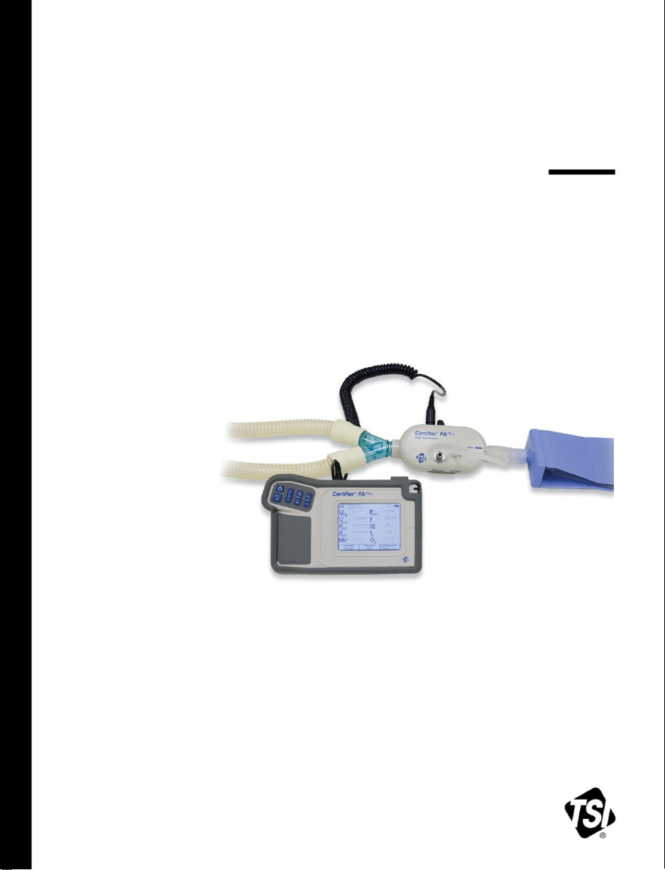
1 Introduction
The Certifier® Flow Analyzer (FA) Test System is a multi-functional pneumatic tester
designed specifically for the medical industry. Specific measurements for ventilator
testing are programmed and include flows, volumes, pressures, oxygen concentration,
and breath timing. The Certifier® FA Plus Test System is designed for hospital, home
care, field service, and laboratory settings.
Certifier® FA Test System components include:
Interface Module:
The keypad and touch screen display allow you to select test measurements and
units for display. The Interface Module connects to the High or Low Flow Module.
High Flow Module:
Measures air, oxygen (O2), nitrogen (N2) and carbon dioxide (CO2) flow rate over a
range of 0 to 300 standard liters per minute (0 to 40 standard L/min for CO2). A
150 PSI (10 Bar) gauge transducer, a barometric pressure transducer, and a
150 cm H2O differential pressure transducer are also in the High Flow Module.
Low Flow Module:
Measures air, O2, N2, CO2 and nitrous oxide (N2O) flow rate over a range of 0.01 to
20 standard L/min with greater accuracy than the High Flow Module at low flow
rates.
Oxygen Sensor:
Used with the High Flow module, allows the High Flow Module to measure O2
concentration and other measurements for any mixture of air and O2.
You can connect or disconnect the flow modules and oxygen sensor at any time during
normal operation without interrupting the operation of the instrument.
Lithium-Ion batteries or an AC adapter can be used to power the test system.
WARNING
To avoid the risk of explosion, do not use in the presence of flammable anesthetic
gases.
Only TSI qualified and trained service technicians are authorized to service the
Certifier® FA Test System.
1
Page 12
2
Caution
1 2 3 6 4
5
7
8 9 10
11
12
13
14
15
19
17
16
18
To avoid inaccurate test readings, do not obstruct tubing or inlet or exhaust ports,
and always use dry gas.
To avoid damage to the Certifier® FA Test System components, always use
bacteria filters upstream of the flow modules, and always cap flow module ports
when not in use.
The Certifier FA Plus is not a medical device under the Medical Device Directive or
FDA 510(k) and in no situation should be used for human measurements.
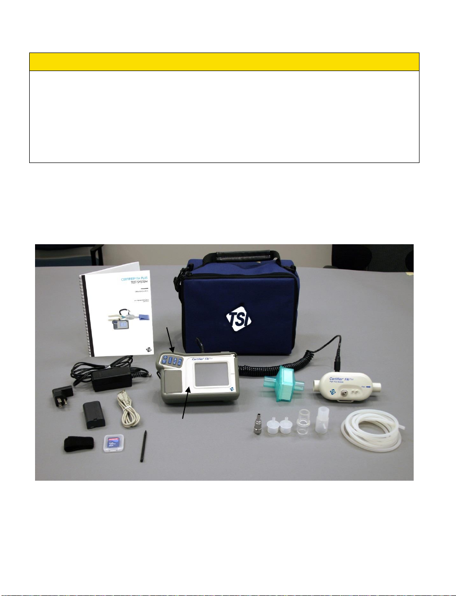
1.1 Parts List
Carefully unpack the test system components from the shipping container. Check the
individual parts against the packing list and notify TSI immediately if anything is missing
or damaged. Table 1 summarizes the Certifier® FA Test System components and part
numbers shown in Figure 1, 2, and 3.
Figure 1. Certifier® FA Test System High Flow Standard Kit (4080)
Certifier® FA Plus Test System
Page 13
Table 1. Certifier® FA Test System Parts List
Item
No.
Description
Replacement
Part Number
Quantity
High Flow Standard Kit (part number 4080)
1 1
Interface Modulea
4088
1
2 2
High Flow Moduleb
4081
1
3 3
Bacteria filter, 22-mm 22-mm male/female, for use
with High Flow Module
1602341
1
4 7
Adapter, 22-mm 6-mm (for interfacing High Flow
Module to Low Flow filter)
1102091
2
5 5
Adapter, 15-mm ID 22-mm OD
1102093
1
6
Airway pressure fitting with screen
1611330
1
7 9
Pressure tubing, silicone, 18-in. ID ¼-in. OD
48-in. (3.2 mm ID 6.4 mm OD 122 cm)
3002053
1
8
Velcro strap for use on High Flow Module
2913133
1
9
Adapter, high pressure port
1611221
1
10
Cable, flow module
1040219
1
11 4
Soft carrying case
1319289
1
12
Power supply 90/260 VAC to +12 VDC
2613237
1
13
Stylus
1319420
2
14
Certifier® FA Test System Operator’s Manual
1980560
1
15
Battery—Lithium-Ion SBL-160
1208056
1
16
Connector, four types:
AC NORTH AM./IEC320, right angle
AC EURO/IEC320, right angle
AC UK/IEC320 fuse, right angle
AC AUST/IEC320, right angle
1302013
1302014
1302015
1302025
1
1
1
1
17
SD flash memory card
1500108
1
18
Protective Rubber boot for Interface module
6001503
1
19
Computer Cable—USB standard A to mini B
1303754
1
a
If ordering a 4088 for replacement, items 10 through 19 are included.
b
If ordering a 4081 for replacement, items 3 through 9 are included
1: Introduction 3
Page 14
4
Item
No.
Description
Replacement
Part Number
Quantity
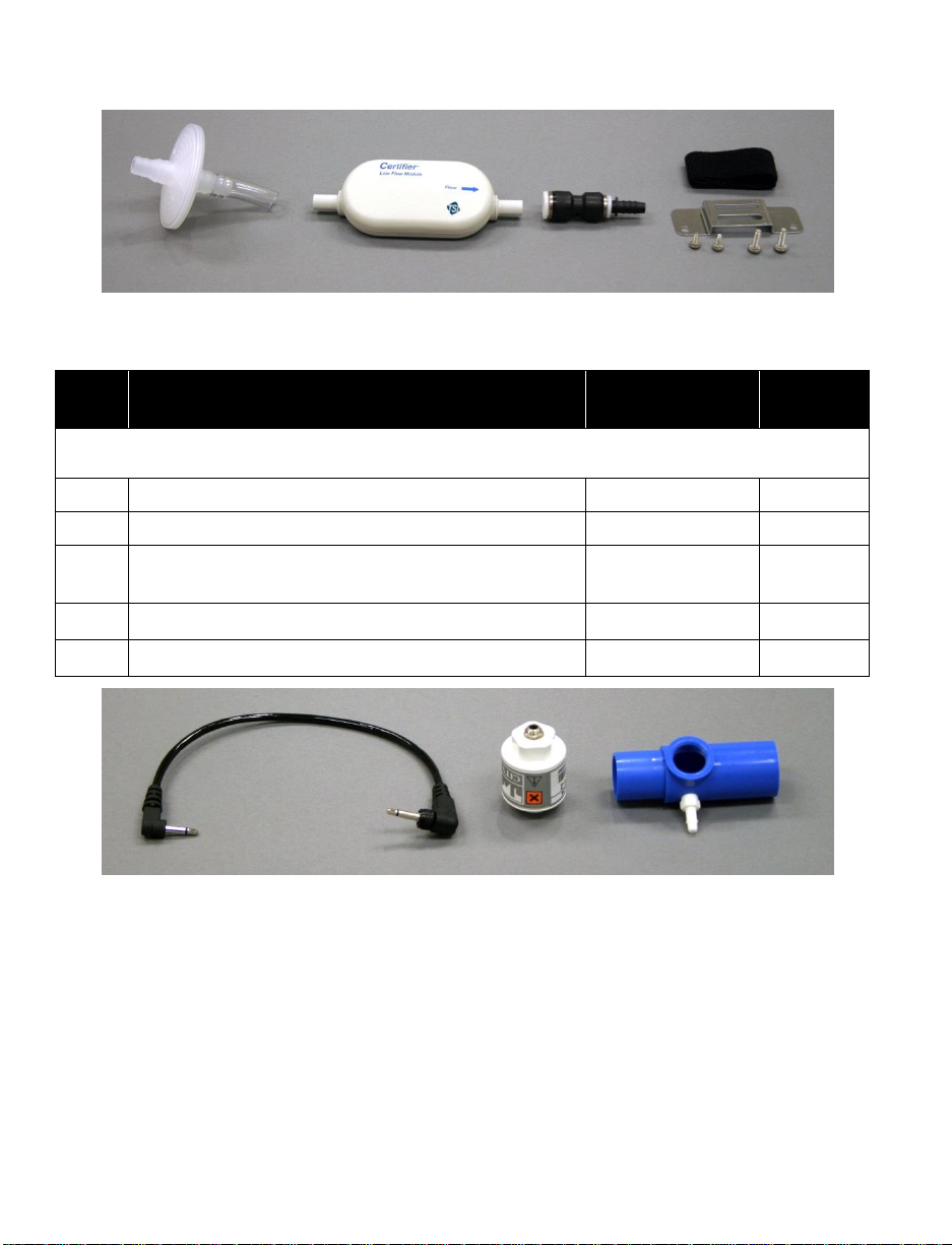
Low Flow Module Kit (optional—part number 4082)
20
Low Flow Module
4082
1
21
Bacteria filter, for use with Low Flow Module
1602342
1
22
Mounting bracket (includes bracket, screws, and
Velcro strap)
1040044
1
23
Coupling,
3
8 inch tube
1601180
1
24
Adapter,
3
8 inch tube to 38 inch barb
1601179
1
20
21
22
23
24
25
26
27
Figure 2. Certifier® FA Test System Low Flow Module Kit (4082)
Figure 3. Certifier® FA Test System Oxygen Sensor Kit (4073)
Certifier® FA Plus Test System
Page 15
Item
No.
Description
Replacement
Part Number
Quantity
Oxygen sensor kit (optional—part number 4073)
25
Oxygen sensor
2917019
1
26
Threaded tee
1313118
1
27
Oxygen sensor cable
1303741
1
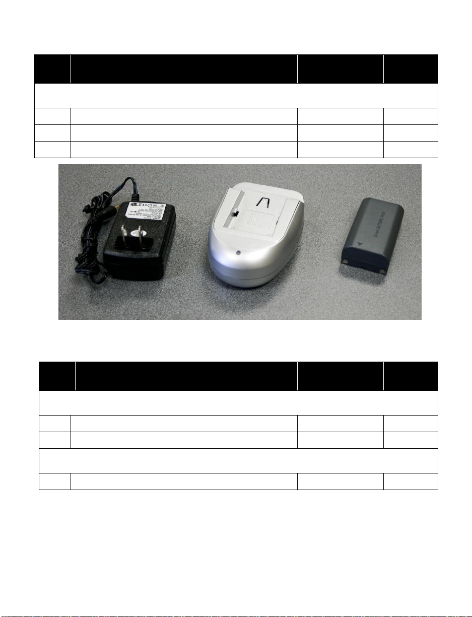
Figure 4. Certifier® FA Test System Extra Battery and Charger Kit (1208061)
Item
No.
Description
Replacement
Part Number
Quantity
Extra Battery and Charger Kit (optional kit – part number 1208061)
28
Battery—Lithium-Ion SBL-160
1208056
1
29
Battery Charger kit
1208059
1
Other accessories (optional)
Printer Cable—USB mini A to standard B
1303860
28
29
1: Introduction 5
Page 16
6
1.2 Glossary
Refer to manual: see Certifier® FA Test System Operator’s Manual for
important information.
CE marking of European Conformity for the Low Voltage Directive (LVD)
and the Directive for Electromagnetic Compatibility (EMCD).
WEEE Directive Label (Waste Electrical and Electronic Equipment). (Item
must be recycled properly.)
Warning symbol. Touch symbol for explanation.
Flow module is working in unidirectional mode. The module is not detecting
a significant amount of negative flows. When testing ventilators,
unidirectional flow is used when the flow module is connected to the To
Patient line
Flow module is in bi-directional flow mode. For ventilators bi-directional flow
is used when the module is between the Y fitting and the test lung.
Battery status symbol. This symbol will indicate how much the battery
charge is left. When no bars are showing instrument will shut off within
minutes.
Battery charging symbol.
>
Start graph or start displaying data on main parameter screen.
||
Pause graph or pause data being displayed on main parameter screen
These labels, terms, and symbols appear on the Certifier® FA Test System:
1.2.1 Symbols on Display
See Available Measurement Parameters in Table 3 for definitions of measurement
symbols and abbreviations that appear on the Certifier FA+ display.
Certifier® FA Plus Test System
Page 17
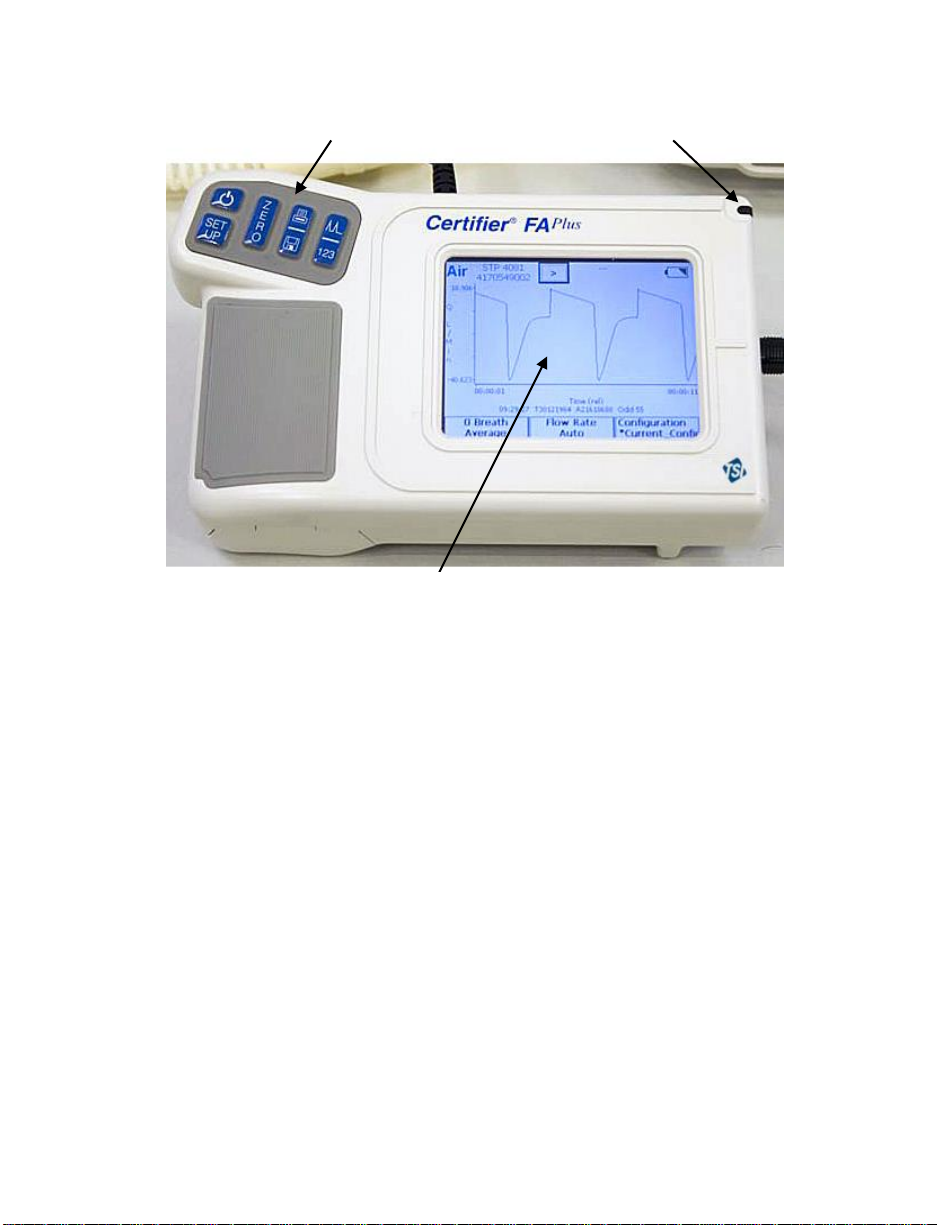
Touch Screen Display
Key Pad
Stylus
Figure 5. Interface Module
1: Introduction 7
Page 18
Certifier® FA Plus Test System
8
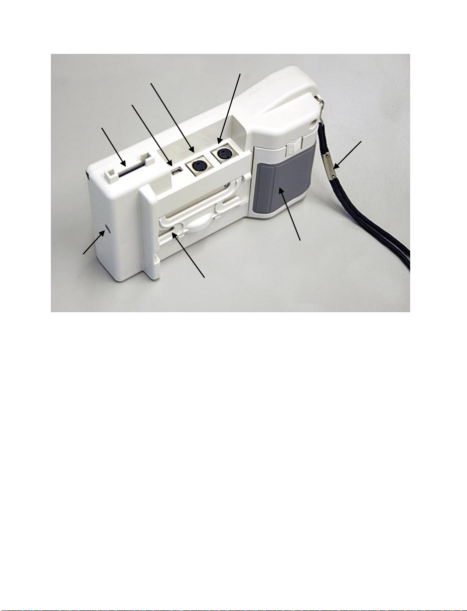
Module B Connector
(not used)
Module A Connector
USB Connector
SD Card Slot
DC
Power
Input
Flip Out Stand
Battery Cover
Wrist Strap
Figure 6. Back of Interface Module
Page 19
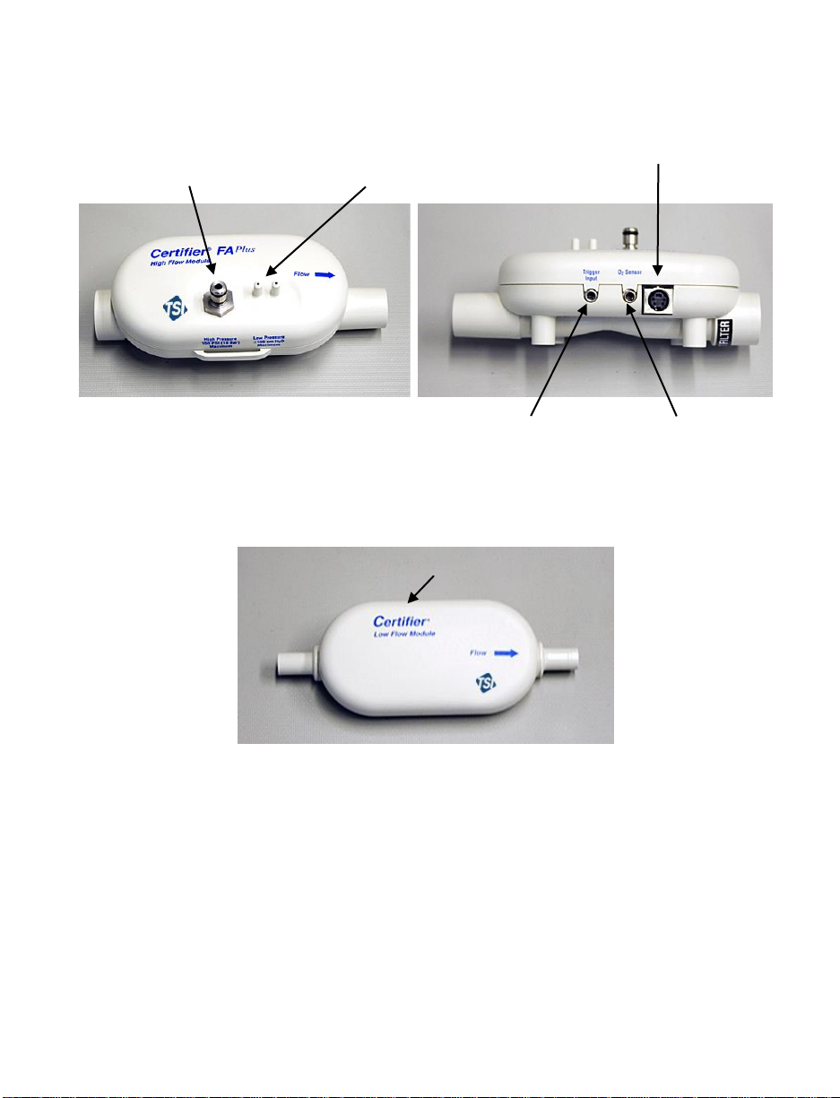
High Pressure
(150 PSIG, 10 bar)
Low Pressure (150 cmH2O
differential)
Use “+” port for airway
pressure.
Coiled Cable Connector
TTL Trigger Input
Oxygen Sensor
Connector
Coiled Cable Connector
Figure 7. High Flow Module
(arrow on module indicates positive flow direction)
Figure 8. Low Flow Module
1: Introduction 9
Page 20

10
Figure 9. Oxygen Sensor Kit
Certifier® FA Plus Test System
Page 21

2 Setup and Operation
Follow these steps to set up the Certifier® FA Test System:
Caution
To avoid damage to the Certifier® FA Test System components, always use bacteria
filters upstream of the flow modules, and always cap flow module ports when not in
use.
1. Install battery if not already installed. Connect AC adapter to DC power source
connector if desired. The battery will charge in the instrument when the AC adapter
is plugged in. Fully charge the battery overnight before using with battery alone.
2. Install SD flash memory card into card slot on top of the interface module. This step
is necessary only if planning to log data.
3. Connect the Interface Module to a flow module (Figure 10). To remove the cable,
pull its locking connector (not the cable) from the Interface Module.
Figure 10. Connecting the Interface Module to a Flow Module
Refer to the manufacturers test procedure for the device under test for
specific instructions on where to connect the Certifier® FA Plus flow module.
The manufacturer of the device under test will also specify which operating
parameters to test.
11
Page 22

4. Install the flow module into the test circuit. Align the flow direction arrow on the flow
module with the positive direction of flow through the circuit; for ventilator testing the
arrow should point towards the test lung or away from the “To Patient” port on the
ventilator.
Figure 11. Installing a Flow Module into the Circuit for Measuring
Bi-directional Flow
(flow direction Arrow should be towards test lung)
12 Certifier® FA Plus Test System
Page 23

Figure 12. Test Circuit for Bi-Directional Flow
Note: If using a test lung with a built in restrictor or a separate restrictor, place the
airway pressure fitting at least 15 cm of the 22 mm tubing between the restrictor
and the flow module. If this is not done, the flow direction sensor may not work
properly.
2: Setup and Operation 13
Page 24

The low flow module is used for testing oxygen concentrators and other low flow
devices. It is not designed for testing ventilators.
The low flow module includes a push-to-fit tube fitting. To install, push tubes into
coupling. To remove fittings, press or pry ring towards the coupling body with a small
screwdriver while pulling coupling away from flow module.
Figure 13. Removing Coupling
14 Certifier® FA Plus Test System
Page 25

Key
Primary Function
On/OFF key
Zeroing Key—Press this key to zero the high and low pressure
transducers.
Print/Save Key—Press this key to print and/or save data. See
Print/Save section (pg. 29) in this manual for more information.
Press this key to switch between the Parameter Screen and Graph
Screen.
Press this key to perform setup on the instrument.
2.1 Keypad Functions
Figure 14. Interface Module Keypad
Table 2. Keypad Functions
2: Setup and Operation 15
Page 26

2.2 Power up
If the device under test is running and creating flow or pressure, temporarily remove the
flow module from the test circuit during power up. This allows the flow direction sensor
on the high flow module to auto calibrate.
Press the I/O (on/off) key on the Interface Module to power up the Certifier® FA Plus
Test System (the Interface Module powers all of the attached Certifier FA Test System
components). At power up, the Interface Module shows information in this sequence
below. After this, return the flow module into the test circuit.
1. Logo screen appears on display for several seconds.
2. One of two types of screens will appear on the display: Graph Screen or
Parameter Screen (see Figures 15 and 16).
3. Wait 1 minute for pressure transducers and flow sensor to warm-up.
4. Perform the pre-test calibrations described in section 2.4.
5. Perform test per the device manufactures procedure (or other appropriate
procedure).
If the AC adapter is plugged into the instrument, the battery charging symbol will
appear on the display.
16 Certifier® FA Plus Test System
Page 27

2.3 Display Navigation
The main two screens are the Parameter Screen and the Graph Screen.
Figure 15. Example of Parameter Screen
Figure 16. Example of Graph Screen
2: Setup and Operation 17
Page 28

By touching on the active areas of the Parameter Screen, you can change the
Stops/Starts
data acquisition
configuration of the display by choosing which parameters to monitor, units of
measure, gas calibration, gas conditions, averaging, and triggering. You can also
save the display configuration to a file or load a previously saved configuration.
18 Certifier® FA Plus Test System
Figure 17. Parameter Screen Features
Page 29

By touching on the active areas of the Graph Screen, you can change the
Stops/Starts
graph
Y-axis setup
Y-axis setup
X-axis setup
configuration of the display by choosing which parameters to plot on the Graph,
units of measure, gas calibration, gas conditions, averaging, triggering, x and y axis
scale. You can also save the display configuration to a file or load a previously
saved configuration.
2: Setup and Operation 19
Figure 18. Graph Screen Features
Page 30

2.3.1 Measurement Selection
Figure 19. Measurement Selection Screen
To add a parameter to the Parameter Screen, touch the parameter and
then touch the right direction arrow. The available parameters change
depending on what module is attached.
To remove a parameter from the Parameter Screen, touch the parameter
and then touch the left direction arrow.
To move a parameter higher on the Parameter Screen, touch the
parameter and then use the up and down direction arrows.
To change the gas calibration used, touch the gas dropdown list and select
the desired gas.
Note: If the gas selection Air/O2 Mixture is selected but no oxygen sensor
is plugged into the Model 4081 high flow module, then the high flow
module will use the internal air calibration only. No corrections for
oxygen concentration will be made if the oxygen sensor is not
plugged into the flow module.
20 Certifier® FA Plus Test System
Page 31

2.3.2 Graph Measurement Selection
Figure 20. Graph Measurement Selection Screen
To add a parameter to Graph, touch the parameter on the left and then
touch the top right direction arrow. Only two parameters can be graphed at
one time. The available parameters change depending on what module is
attached.
To remove a parameter from the graph, touch the parameter and then
touch the top left direction arrow.
To change the gas calibration used, touch the gas dropdown list and select
the desired gas.
To add a parameter to the label section below the graph, touch the
parameter and then touch the bottom right direction arrow. Only four
parameters can be in this section.
To remove a parameter from the Parameter Screen, touch the parameter
and then touch the bottom left direction arrow.
After clicking OK, a prompt will appear to enter the units of measurement.
Note: Up to two parameters may be graphed simultaneously; whereas up
to four parameters may be viewed simultaneously on the Graph
page.
2: Setup and Operation 21
Page 32

Flow Rate. “Q” is used on the
Graph Screen.
High pressure transducer
(4081 only)
Peak Flow Rate—Peak Inhaled
Flow Rate. “Qpeak” is used on
the Graph Screen.
Absolute pressure in flow tube.
If flow tube open to
atmosphere, then this is also
the barometric pressure
Minimum Flow Rate—In BiDirectional Mode this is the
Negative of the Peak Exhaled
Flow Rate. “Qmin” is used on
the Graph Screen.
Oxygen concentration (with
both 4081 and 4073 only)
Inhaled tidal volume
Temperature of gas (accurate
for flows above 5 L/min)
Exhaled tidal volume (4081
only)
Frequency—Breath rate
V
Real-time volume (graphing
only)
Inspiratory time
Inhaled minute tidal volume
Inspiratory pause time (4081
only)
Low pressure transducer—
Airway pressure (4081 only)
Inspiratory time including the
pause time
Peak Inspiratory pressure (4081
only)
Expiratory time
Peak End Expiratory Pressure
(4081 only)
I to E ratio
Mean Airway Pressure (4081
only)
I to E ratio which includes
inspiratory pause time
Minimum low Pressure (4081
only)
Time of day
Delta low pressure—Delta
airway pressure (4081 only)
2.3.3 Available Measurement Parameters
Table 3. Parameters (parameter list changes depending on module attached)
2: Setup and Operation 22
Page 33

I:E = t
E
/ t
I
I:E
IP
= t
E
/ t
I+P
f = 1
/ (t
I+P
+ t
E
)
MV = V
TI
f
2: Setup and Operation 23
Figure 21. Parameter Definitions
Page 34

2.3.4 Gas Conditions Selection Box
STP
Standard Temperature and Pressure. The gas flow rate and volumes
are displayed in terms of what the gas flow rate and volume would be if
the gas was 21°C and 1 atmosphere (101.3 kPa) of pressure.
ATP
Actual Temperature and Pressure. The gas flow rate and volumes at
the actual temperature and pressure of the gas.
BTPS
Body temperature and Pressure Saturated. The gas flow rate and
volumes are displayed in terms of what the gas flow rate and volume
would be if the gas was changed to 37°C, the actual pressure, and also
saturated with water vapor.
BTPD
Body temperature and Pressure Dry The gas flow rate and volumes
are displayed in terms of what the gas flow rate and volume would be if
the gas was changed to 37°C, but maintaining the actual pressure.
STPxx
User defined Standard Conditions. The gas flow rate and volumes are
displayed in terms of what the gas flow rate and volume would be if the
gas was at the conditions entered in the boxes to the right.
Figure 22. Gas Conditions Selection Box
24 Certifier® FA Plus Test System
Page 35

2.3.5 Averaging Setup Menu
Number of Breaths
Averaged
All breath parameters are averaged over the selected
number of breaths.
Second Average for
Real-Time Values
All displayed transducer measurements are averaged over
the selected number of seconds. Transducer
measurements include: flow, low pressure, high pressure,
absolute pressure, oxygen concentration, and temperature.
Figure 23. Averaging Setup Menu
2: Setup and Operation 25
Page 36

2.3.6 Breath Trigger Types
Flow Rate
Start and end of the breath is determined by the specified
flow rate. If Auto-Triggering is selected, instrument tries to
determine trigger levels. In some cases you may need to
manually select the flow rates by looking at the flow
waveform on the Graph Screen.
Pressure
Start and end of the breath is determined by the specified
pressure levels. Positive slope changed through the first
value is used for the start of inspiratory and a negative
slope through the second value is used for the start of
expiratory. Note: This trigger type is intended to give
advance users additional setup options for special
circumstances, such as achieving basic breath
measurements from high frequency ventilators or other
setups in which flow rate or auto triggering are non-ideal.
TTL
Start and end of the breath is determined by a TTL voltage
signal given at the connector on the High Flow Module
labeled “Trigger Input”. This is only available for the 4081
High Flow Module. The connector is a 3.5 mm mono audio
jack plug.
This screen defines how the start of the inspiratory breath cycle and the expiratory
breath cycle are detected. Under most circumstances, it is recommended that the autotrigger be used.
Figure 24. Trigger Options Menu
26 Certifier® FA Plus Test System
Page 37

2.3.7 Flow Triggering
If auto-triggering is not providing reasonable results, consider using either manual flow
or manual pressure triggering. To use manual flow triggering, select the flow radio
button and uncheck the "Auto-Triggering" checkbox. Similarly, to use manual pressure
triggering, select the pressure radio button. For a breath to be detected, trigger settings
must be set appropriately for the waveform of interest. There are two suggested
methods for determining the appropriate start and end trigger values: 1) switch the
Certifier FA Plus Test System to the graphing screen and observe the flow or pressure
readings at the start and the end of inspiration and 2) observe the flow and pressure
wave form from the ventilator being tested. For robust flow and pressure triggering
always set the "End Trigger" level lower than the "Start Trigger". For example, a manual
flow trigger setting may be +5 L/min for a start trigger and -5 L/min for an end trigger
setting. These numbers can be optimized based upon your specific application.
2: Setup and Operation 27
Page 38

2.3.8 Saving/Loading Configurations
Configuration is saved
under current name and
location
Configuration of the values displayed, gas, conditions, triggering, and graph setup can
be saved and recalled. This allows the user to save configurations for different
equipment.
See section 2.3.10.1 to learn how to transfer configuration files from one instrument to
another using the SD memory card.
28 Certifier® FA Plus Test System
Figure 25. Configuration Save Screen
Page 39

2.3.9 Print/Save Button
Figure 26. Print/Save Options Screen
If the Print/Save button is pressed while viewing the Parameter Screen, the "Print/Save
Options" screen will appear. By selecting the various options on this screen you will be
able to:
Print the current data record without saving to a file.
Print the current data record and also save it to a file in a single operation.
Save the current data record to a file without printing.
Select Waveform logging function. This feature saves 15 seconds of "raw"
flowmeter data at a rate of 1 millisecond/reading to a file (requires an SD Flash
memory card).
Select Continuous logging function. This mode logs the Parameter Screen data
into a file at intervals of approximately 1 second until you command the logging to
stop (requires an SD Flash memory card).
When printing or saving, you can add custom comments to your data by selecting the
Add Comments option. When that option is selected, an on-screen keyboard appears,
allowing you to enter your comment text.
2: Setup and Operation 29
Page 40

Figure 27. Add Comments Screen
If the Print/Save button is pressed while viewing the Graph Screen, you will be able to
Save the currently displayed Graph data to a file to either the built-in Internal Memory or
to an SD Flash card inserted into the SD Card slot. You cannot print the Graph or the
Graph data and you cannot print or save a screen shot of the graph.
To retrieve data from the Certifier test system, simply connect the device to a PC using
an USB standard A to mini-B cable. Use the Setup function “Select Mass Storage
Target” (see section 2.3.10 “Setup Key”) to choose whether the host PC will access the
Certifier test system’s built-in memory, or an SD Flash card inserted in the card slot of
the Certifier test system.
All data files exported from Certifier test system use the ASCII character set and
"comma separated value" (CSV) format. This is a format that most spreadsheet and
database applications can import. See Advanced Features Menu for selecting file
delimeters other than commas.
2.3.9.1 Waveform Logging
The Waveform Logging feature logs 15 seconds of raw flowmeter data into a file on a
SD Flash card. The logging rate is about once per millisecond. The data is exported into
“comma separated value” (CSV) format, readable by many common spreadsheet and
database applications. See Advanced Features Menu for selecting file delimeters other
than commas.
The Waveform logging feature requires an SD Flash card.
30 Certifier® FA Plus Test System
Page 41

To initiate Waveform logging:
Press the Print/Save button on the Certifier test system keypad.
Select Waveform from the Logging Features section.
You may choose to Add Comments if you would like to annotate the data.
Click OK, add comments (if selected) and name the file.
The Certifier test system will collect 15 seconds of flowmeter waveform data and
then save it into the file.
Access the data by connecting the Certifier test system to a host computer via USB, or
by removing the SD Flash card from the Certifier test system and inserting it into a card
reader attached to a host computer.
2.3.9.2 Continuous Logging
The Continuous Logging feature will log snapshots of the same data being displayed on
the Certifier Parameter Screen and log it into a file on an SD Flash card. The logging
rate is once per second. Only data displayed on the Certifier Parameter Screen will be
logged. See section 2.3 on how to add or remove parameters. The data is exported into
“comma separated value” (CSV) format, readable by many common spreadsheet and
database applications. See Advanced Features Menu for selecting file delimeters other
than commas.
The Continuous logging feature requires an SD Flash card.
To initiate Continuous logging:
Press the Print/Save button on the Certifier test system keypad.
Select Continuous from the Logging Features section.
You may choose to Add Comments if you would like to annotate the data.
Click OK, add comments (if selected) and name the file.
The Certifier test system will continue to log data until the Print/Save button is
pressed again or until the SD Flash card fills up.
Access the data by connecting the Certifier test system to a host computer via USB, or
by removing the SD Flash card from the Certifier test system and inserting it into a card
reader attached to a host computer.
Note: If the pause button was pressed prior to continuous logging, a slight delay may
be noticed in the start of the data acquisition.
2: Setup and Operation 31
Page 42

2.3.10 Setup Key
Oxygen Sensor Calibration
See required pre-test section of this manual.
Set Time/Date
Sets the current time and date.
Touch Screen Calibration
Calibrates the touch screen of the interface module. Follow the instructions
on the display.
Lock Touch Screen
Disables the touch screen once the Setup Menu is closed. To enable the
touch screen, press the Setup button.
Lock Configuration
Disables the saving of configurations. The user will be able to load existing
configurations and change the current configuration, but not save it.
Advanced Features
See section 2.3.10.1 for a complete list of advanced features which can be
accessed through this menu.
About Device
Displays information about the Certifier Interface Module and any connected
flow module.
Figure 28. Setup Menu
32 Certifier® FA Plus Test System
Page 43

Select Mass Storage Target
When the Certifier test system is connected to a host computer via USB
interface, it appears to the host as a "mass storage" device, similar to a
"memory stick" or “thumb drive”. This function allows you to select whether
the host can access the Certifier's Internal Memory or an SD Flash memory
card. The Certifier test system supports SD flash cards up to 1 GB in size.
Restart the Certifier whenever a change if made when selecting between
internal flash RAM and SD flash card.
2.3.10.1 Advanced Features
Figure 29. Advanced Function Menu
2.3.10.1.1 Configuration Import/Export
This feature enables you to both download and upload configuration files to and from
the SD card. This is convenient when multiple Certifier FA+ units are in use where the
configuration files from one unit can be transferred to multiple Certifier units. This
eliminates the need to generate configuration files for each instrument.
This feature requires an SD card to be inserted in the instrument. If it is desired to view
the configuration file on a PC, be sure the Select Mass Storage Device setting is
configured to SD card as mentioned in section 2.3.10.
Press Export button to export the configuration file to the SD card.
Press Import to import the configurations from the SD card.
2: Setup and Operation 33
Page 44

Notes about exporting configuration files:
All data is saved to a single file called CertifierConfigurations.dat. If this file already
exists on the SD card, it will be overwritten each time the Export command is
executed.
It is not possible to generate a user-selectable filename for the exported
configurations.
Notes about importing configuration files:
Importing a configuration which already exists under the same name in the Certifier
memory will cause the configuration in memory to be overwritten.
Importing a configuration file will not erase existing configuration files which already
exist in memory but under a different configuration name.
This feature is not designed for creating configuration files on a PC. The feature is
primarily designed to transfer configuration files from one instrument to another.
2.3.10.1.2 Format Settings
Figure 30. Format Settings Screen
Different formats of the date can be selected from this menu. This information is used in
the file save mode as part of the filename and also stored internally within the file.
Different data delimeters used in the file save function can be selected through this
menu. This allows for greater flexibility for importing data in different regions of the
world.
34 Certifier® FA Plus Test System
Page 45

Caution
To ensure accurate measurements, wait one minute for the Certifier® FA Test
System to warm up. If environmental conditions have changed significantly, more
time may be necessary.
To avoid damage to the Certifier® FA Test System components, always use
bacteria filters upstream of the flow modules, and always cap flow module ports
when not in use.
If liquid has penetrated any of its components, do not use, and return to the factory
for calibration.
2.4 Required Pre-test Calibrations
2.4.1 Low Flow Module
2.4.1.1 None required
2.4.2 High Flow Module
2.4.2.1 Zeroing the Flow Direction Sensor
The model 4081, High Flow Module, has a sensor that is used to detect the direction of
flow. This sensor will normally auto-zero if there is no flow for a fraction of a second. If it
is unable to do this at power-up or at least every 10 minutes, a appears on the
screen. Touch the symbol on the display for an explanation of the warning. To manually
zero the direction sensor, remove the High Flow Module from the flow source and cover
one end of the flow tube for a couple of seconds.
2.4.2.2 Low-Pressure and High-Pressure Transducer Zeroing
Check the Low-pressure transducer zero and a High pressure transducer zero by
disconnecting the pressure tubing from the flow module before each pressure
measurement after initial power up to ensure the most accurate readings. If the low or
high pressure is not reading zero, perform the following steps to zero the transducers.
1. Disconnect the pressure tubing from the low and high pressure ports.
2. Press the key.
3. “Pressure Transducers Zeroing” appears on the display for one second. If the
transducers do not see a steady pressure or near zero pressure, an error appears.
NOTE: The barometric pressure transducer does not require a zero calibration.
2: Setup and Operation 35
Page 46

2.4.2.3 Oxygen Sensor Calibration
Follow these steps daily and following an altitude change or sensor replacement to
calibrate the oxygen sensor:
1. Power up the Certifier® FA Test System with the High Flow Module and oxygen
sensor attached, allow one minute to warm up.
2. Press the key and select the “Oxygen Calibration” box on the display. Follow
the directions on the screen. Note that either an “air only” or an “air and 100%
oxygen” calibration can be done. The two point air/100% oxygen calibrations
provide the best accuracy.
Note: The numeric value displayed during the stabilization process does not
necessarily represent the actual oxygen concentration. This numeric
stabilization value is there for you to determine if it is changing or not. Once
the reading stops changing then it is time to advance to the next step in the
oxygen sensor calibration process.
36 Certifier® FA Plus Test System
Page 47

Symptom
Possible Cause
Corrective Action
Interface Module won’t
turn on, or turns on
and off.
Batteries are depleted or
not installed.
Connect AC adapter or install
charged batteries.
Measurements are not
displayed even though
Interface Module is
turned on.
Flow module is not
connected to Interface
Module.
Connect flow module to Interface
Module. If connected, disconnect
and then reconnect.
Measurements are not
changing or graph is
not updating.
Pause button was
pressed.
Press the Play button at the
top of the screen.
“OOR” is shown on
display.
Measurement is out of
range.
Check range for displayed
measurement, and only make
measurements within that range.
Flow rate does not
read zero when no gas
flowing (Especially
when set to N2O or
CO2).
Meter was not purged
with gas displayed on the
Interface Module.
Purge meter with gas displayed
on Interface Module or press gas
select key to change to desired
gas.
Unable to disconnect
flow module from
Interface Module.
Pulling on the cable
rather than the connector.
Pull the locking connector (not
the cable) to disengage
connector lock.
3 Troubleshooting
Table 4 lists the symptoms, possible causes, and recommended corrective actions for
problems you may encounter with the Certifier® FA Test System. If the symptom is not
listed, or if none of the recommended corrective actions solve the problem, please visit
our website at http://service.tsi.com or contact TSI Customer Support at (800) 874-2811
or 651-490-2811.
Table 4. Troubleshooting the Certifier® FA Test System
37
Page 48

Symptom
Possible Cause
Corrective Action
Volume, minute
volume, peak flow,
peak pressure, PEEP,
respiratory rate, or I:E
ratio measurement are
not updated or
incorrect.
Less than two
consecutive full breaths
have been supplied to
flow module, or flow is not
supplied as a breathing
waveform.
Auto-trigger not optimized
for current waveform.
Airway restrictor causing
flow disturbance next to
flow module.
Flow condition causing
oscillations in the
waveform.
Wait for at least two consecutive
full breaths to be supplied to the
flow module.
Ensure that flow is supplied as a
breathing waveform.
Manually set flow trigger level.
Use the TSI Airway pressure
fitting which contains the screen
between the flow module and
the test lung (see Figure 12).
Minimize length of tubing
between the test lung and the
airway pressure fitting.
I:E ratio or I time
readings do not
appear correct.
It is possible the
inspiratory pause function
is turned on inside the
ventilator.
Select the I time parameter T
I+P
and ratio parameter I:EIP to be
on the display when the
inspiratory pause feature is
activated on the ventilator. See
section 2.3.3 for a description of
the difference between TI and
T
I+p
.
Another option is to turn off the
inspiratory pause feature on the
ventilator.
Can’t zero lowpressure or high
pressure transducer.
Transducer is connected
to a pressure source.
Disconnect pressure tubing from
flow module and then zero lowpressure transducer.
Can’t zero barometric
pressure transducer.
Barometric pressure
transducer does not
require a zero calibration.
Resume normal system
operation.
38 Certifier® FA Plus Test System
Page 49

Symptom
Possible Cause
Corrective Action
Oxygen sensor
calibration fails.
21% oxygen and/or 100%
oxygen not supplied for
calibration.
Oxygen sensor is
expired.
Non-steady flow or tidal
flows used.
Verify that calibration gases are
21% oxygen and 100% oxygen
and repeat calibration.
Replace oxygen sensor.
Use constant flow rates to
supply calibration gas.
Pressure trigger gives
erroneous results.
Pressure signal supplied
to high-flow module not
correct.
Change source of pressure
signal.
Pressure trigger optimized for
use with high-frequency
ventilators.
Host computer not
able to view internal
memory or SD flash
memory.
Certifier test system was
not restarted after
selecting mass storage
target location.
Turn Certifier off and then on
again.
3: Troubleshooting 39
Page 50

(This page intentionally left blank)
40 Certifier® FA Plus Test System
Page 51

Component
Cleaning
Interface Module
Flow modules
Carrying cases
Oxygen sensor
Oxygen sensor cables
Clean exterior as required with a clean cloth and
isopropyl alcohol, hydrogen peroxide (3%), or ammonia
(15%).
Tee
Adapters
Steam autoclave after contact with any non-sterile
breathing circuit components, and discard if any
damage is visible.
Single use filters (High
and Low Flow
Modules)
Discard after contact with any non-sterile breathing
circuit components or if damage is visible.
4 Maintenance
4.1 Recharging the Batteries (as required)
The batteries can be charged internally by connecting the AC adapter or they can be
charged externally with the optional battery charger. The fastest charging method is to
charge the battery in the instrument with the instrument turned off. The Certifier FA Plus
uses SBL-160, Lithium Ion Batteries, which are available from many battery supply
houses or TSI. Charging time is approximately 4 to 6 hours.
4.2 Replacing the Oxygen Sensor
The oxygen sensor will function for one or more years of normal operation if use begins
before the expiration date. Replace the oxygen sensor every year or two of normal use,
or if the sensor cannot be calibrated or sensor readings are erratic.
4.3 Cleaning (as required)
Table 5 summarizes recommended cleaning methods for Certifier® FA Test System
components.
Table 5. Cleaning Recommendations
41
Page 52

4.4 Factory Calibration (recommended yearly)
Certifier® FA Test System flow modules are designed for one year of normal use
following each factory calibration.
If the test system has been dropped or liquid has penetrated any of its components, do
not use, and return to the factory for calibration.
Recalibrated flow modules come with a certificate of calibration and a summary of
performance before and after the calibration. A factory calibration consists of pressure
transducer calibration over the full range of pressures and calibration over the full range
of flows. All calibration datum are stored in the flow modules, so the Interface Module
does not require calibration. Therefore, it is not necessary to return the Interface
Module for factory calibration.
Follow the steps in Section 4.5 to return Certifier® FA Test System flow modules for
factory calibration.
4.5 Return Procedure
Follow these steps to return Certifier® FA Test System flow modules for factory
calibration:
1. Obtain a Return Material Authorization (RMA) number using our online RMA form at
rma.tsi.com or contact one of the following offices to make service arrangements.
2. Package the flow modules carefully to avoid damage during shipping.
NOTE: It is not necessary to return the Interface Module for factory calibration.
U.S. & International United Kingdom
TSI Incorporated TSI Instruments Ltd.
500 Cardigan Road Tel: (44) 1494 459200
Shoreview MN 55126-3996 Fax: (44) 1494 459700
USA E-mail: tsiuk@tsi.com
Tel: (800) 874-2811 / Website: www.tsiinc.co.uk
+1(651) 490-2811
Fax: +1(651) 490-3824 Germany
E-mail: technical.service@tsi.com TSI GmbH
Website: www.tsi.com Tel: +49 241-52303-0
Fax: +49 241-52303-49
E-mail: tsigmbh@tsi.com
Website: www.tsiinc.de
42 Certifier® FA Plus Test System
Page 53

Dimensions
Interface module: 17.3 cm 10.5 cm 4.5 cm (6.8 in. 4.1 in.
1.8 in.)
High Flow Module: 15 cm 6.7 cm 6.1 cm (5.9 in. 2.7 in. 1.4 in.).
Low Flow Module: 12.7 cm 5.1 cm 2.8 cm (5.0 in. 2.0 in.
1.1 in.).
Flow
connectors
High Flow Module:
Flow inlet: 22-mm female ISO taper.
Flow outlet: 22-mm male ISO taper.
Low Flow Module:
Flow inlet: 3/8-in.
Flow outlet: 3/8-in.
Weight
Approximately 0.7 kg (1.5 lb), interface with high flow module and
cable.
Temperature
Operating: 5 to 40C (41 to 104F). 15 to 80% relative humidity from 5
to 31C decreasing linearly to 15 to 50% relative humidity at 40C.
Storage: -40 to 70C (-40 to 158F) at 10 to 90% relative humidity,
non-condensing
Atmospheric
Pressure
Operating: 57.1 to 106 kPa (8.28 to 15.37 psia).
Storage: 15000 meters
Conditions
Indoor Use
Operating Altitude up to 4000 m (13,000 ft)
Pollution degree I or II
Battery Life
3 to 6 hours typical
Battery Type
Lithium-Ion SBL160
AC Adapter
12 VDC 1A Minimum
5 Specifications
NOTE: Specifications are subject to change without notice.
5.1 Physical
5.2 Environmental
5.3 Power
43
Page 54

5.4 Data Transfer and Storage
Internal Memory
1 MB (500 typical records)
External Memory
SD Flash Card. Supports up to 1 GB cards.
Measurement
High Flow Module
Low Flow Module
Flows
Range
-200 to +300.0 SLPM air,
oxygen, and nitrogen
-40 to +40 SLPM carbon
dioxide
0 to 300 air/oxygen mixture
0.01 to 20.00 SLPM air, oxygen,
nitrogen, carbon dioxide, and
nitrous oxide
Accuracy
Air and oxygen: ±2% of reading
or ±0.075 standard L/min,
whichever is greater
Nitrogen and carbon dioxide:
±3% of reading or ±0.075
standard L/min, whichever is
greater
Air/Oxygen mixture: ±4% of
reading or ±0.100 standard
L/min, whichever is greater
Air and oxygen: ±2% of reading or
±0.010 standard L/min, whichever is
greater
Nitrogen and carbon dioxide: ±3%
of reading or ±0.010 standard
L/min, whichever is greater
Nitrous oxide: ±4% of reading or
±0.025 standard L/min, whichever is
greater
Volumes
Range
0.01 to 10 L STP
0 to 10 L STP
Accuracy
Air and oxygen: 2% of reading
plus 0.020 L
Air/oxygen mixtures: 4% of
reading plus 0.020 L STP
Air and oxygen: 2% of reading or
0.010 L, whichever is greater
Nitrous oxide: 4% of reading or
0.010 L STP, whichever is greater
5.5 Test Measurements (See notes at end of section. See Table 3 for symbol definitions.)
44 Certifier® FA Plus Test System
Page 55

Measurement
High Flow Module
Low Flow Module
Volumes
Range
0.01 to 10 L STP
Not applicable
Accuracy
Air and oxygen: 3% of reading
plus 0.030 L
Air/oxygen mixtures: 4% of
reading plus 0.040 L STP
Not applicable
Minute Volume
Range
0.01 to 100 L STP
0 to 10 L STP
Accuracy
3% of reading
3% of reading
Times
Range
0.04 to 30 seconds
0.04 to 30 seconds
Accuracy
2% of reading or 0.01
seconds, whichever is greater
2% of reading or 0.01 seconds,
whichever is greater
I:E Ratios
Range
1:100.0 to 100.0:1
1:100.0 to 100.0:1
Accuracy
4% of reading typical
4% of reading typical
Respiratory Rate
Range
1 to 1500 breaths per minute
1 to 1500 breaths per minute
Accuracy
2% of reading or 0.1 BPM,
whichever is greater
2% of reading or 0.1 BPM,
whichever is greater
Low Pressures
Range
-25.0 to 150.0 cmH2O.
(-18.4 to 110 mmHg)
Not applicable
Accuracy
0.5% of reading or
0.15 cmH2O (0.15 mmHg),
whichever is greater
Not applicable
5: Specifications 45
Page 56

46 Certifier® FA Plus Test System
Measurement
High Flow Module
Low Flow Module
High Pressure
Range
-10 to 150.0PSIG (-0.7 to 10
bar)
Not applicable
Accuracy
1% of reading or 0.1 PSI
(7 mbar), whichever is
greater.
Not applicable
Absolute Pressure
Range
375 to 1200 mmHg (500 to
1600 mbar)
375 to 1500 mmHg (500 to
2000 mbar)
Accuracy
8 mmHg (11 m bar)
8 mmHg (11 mbar)
Oxygen Concentration
Range
21 to 100%
Not applicable
Accuracy
2% concentration
Not applicable.
Temperature
Range
5 to 40°C
5 to 40°C
Accuracy
1°C When flow rates are
above 2 L/min
1°C When flow rates are above
2 L/min
Page 57

Measurement
High Flow Module
Low Flow Module
NOTES
1. Standard conditions are defined as 21.1C (70F) and 101.3 kPa (14.7 psia).
2. Flow and volume accuracy is applicable at these standard conditions (see note 1).
3. For the High Flow Module the temperature of the gas and the ambient air must be
within 10C (18F) of each other and the gas must be less than 30% relative
humidity at 21.1C (70F).
For the Low Flow Module the temperature of the gas and the ambient air must be
within 5C (9F) of each other and the gas must be less than 30% relative
humidity at 21.1C (70F).
4. Flow and volume accuracy de-rating: 0.075% of reading per 1C (1.8F) away
from 21.1C (70F); 0.015% of reading per 1.03 kPa (0.15 psia) above 101.3 kPa
(14.7 psia); 0.022% of reading per 1.03 kPa (0.15 psia) below 101.3 kPa (14.7
psia); 0.07% of reading per 1% relative humidity above 30% relative humidity.
The Low Flow Module has an additional flow rate accuracy de-rating of 0.0003
standard L/min per 1C (1.8F) and 1 kPa away from 21.1C (70F) and 101.3kPa.
5.6 Calibration Recommendations
Flow
Modules
Start with factory calibration every year for use under normal
conditions using the filter(s) provided.
Interface
Module
No calibration required.
Oxygen
Sensor
Check Daily, calibrate as needed.
Complies
with these
standards:
EN 55011 (1991) Class B, CISPR 11 (1990) Class B, FCC (CFR
47, Part 15) Class B: Emissions, Radiated and Conducted.
EMC Directive 89/336/ECC, EN 61326-1 (1997 plus Amendment
A1 1998), IEC 1000-4-2 (1995), EN 61000-4-2, IEC 1000-4-3
(1995), EN 61000-4-3: Immunity.
5.7 Compliance and Approvals
5: Specifications 47
Page 58

(This page intentionally left blank)
48 Certifier® FA Plus Test System
Page 59

Appendix A Data File Formats
Parameter Screen Single Sample and Continuous Logging Data
Format
Raw Text Example:
Filename:,\NV1FLASH\EXAMPLE.csv
Comments:,Custom comments here
Configuration:,*Current Configuration
Module A Model:,4081
Module A SN:,40810705010
Trigger Type:,Flow Rate
Start Trigger:,Auto
End Trigger:,Auto
Module A Conditions:,STP
Module A Gas:,AIR
Data Section:,,Module A,Module A,Module A
,,Flow Rate,Low Pressure,PEEP Pressure
Date,Time,L/Min,cmH2O,cmH2O
27/12/2007,12:03:20,0.00,-0.256,0.000
49
Page 60

As Formatted By spreadsheet application:
Filename:
\NV1FLASH\EXAMPLE.csv
Comments:
Custom comments here
Configuration:
*Current Configuration
Module A
Model:
4081
Module A SN:
40810705010
Trigger Type:
Flow Rate
Start Trigger:
Auto
End Trigger:
Auto
Module A
Conditions:
STP
Module A Gas:
AIR Data Section:
Module A
Module A
Module A
Flow Rate
Low
Pressure
PEEP
Pressure
Date
Time
L/Min
cmH2O
cmH2O
27/12/2007
12:03:20
-19.2
-0.256
0
Notes:
When Continuous logging is used, each additional reading is given on a separate,
appended text line.
Parameter value columns are formatted in the same order that they have been
configured on the display screen.
Parameter Screen Waveform Logging Data Format
Waveform Logging collects a 15-second snapshot of “raw” data from the connected
flow module. An example of the data collected in waveform logging is shown below.
50 Certifier® FA Plus Test System
Page 61

Raw Text Example (waveform logging):
Appendix A Data File Formats 51
Page 62

Graph Screen Data Format
The Graph Display data is formatted as 2 (1 parameter on Graph) or 3 (2 parameters
on Graph) columns of text. The first column is the X axis (relative time), the second and
third columns will contain the Graph data.
X Q L/Min P cmH2O
Total graph time: 10 seconds.
0 -0.421556 0.673527
0.041 -0.197457 0.678888
0.082 -0.095008 0.693449
0.123 -0.043302 0.699908
0.1639 -0.027286 0.712823
0.2049 -0.027088 0.723274
0.2459 -0.022927 0.730932
0.2869 -0.019958 0.736425
0.3279 -0.019294 0.738421
0.3689 -0.022878 0.740417
0.4098 -0.024059 0.744878
0.4508 -0.030267 0.744917
0.4918 -0.034957 0.747344
0.5328 -0.040919 0.74523
0.5738 -0.046022 0.740886
0.6148 -0.04976 0.749106
0.6557 -0.049111 0.743039
0.6967 -0.049844 0.742413
[up to 244 data points]
52 Certifier® FA Plus Test System
Page 63

USA Tel: +1 800 874 2811
UK Tel: +44 149 4 459200
France Tel: +33 1 41 19 21 99
Germany Tel: +49 241 523030
India Tel: +91 80 67877200
China Tel: +86 10 8219 7688
Singapore Tel: +65 6595 6388
TSI Incorporated – Visit our website www.tsi.com for more information.
P/N 1980560 Rev J Copyright © 2016 by TSI Incorporated Printed in U.S.A.
*1980560*
 Loading...