

TSI Incorporated CA-CALC, CA-6200 Operation And Service Manual

Combustion Analysis
Series 6200
TM
CA-CALC
Combustion Analyzers
Operation and Service Manual
1980431 Rev. F
January 2004


Series CA-6200
CA-CALC
TM
Combustion Analyzers
Operation and Service
Manual
January 2004
P/N 1980431 Rev. F
U.S. AND CANADA OTHER COUNTRIES
Sales & Customer Service:
(800) 874-2811/(651) 490-2811 (001 651) 490-2811
Fax:
Fax:
(651) 490-3824 (001 651) 490-3824
MAIL/SHIP TO: E-Mail
TSI Incorporated answers@tsi.com
ATTN: Customer Service
500 Cardigan Road WEB SITE
Shoreview, MN 55126 www.tsi.com
USA
Sales & Customer Service:

Copyright ©
TSI Incorporated / 2001–2004 / All rights reserved.
Part Number
1980431 / Revision 5
Address
TSI Incorporated / 500 Cardigan Road / Shoreview, MN 55126 / USA
Fax No.
(651) 490-3824
LIMITATION OF WARRANTY AND LIABILITY (effective July 2000)
Seller warrants the goods sold hereunder, under normal use and service as described in the operator's manual, shall
be free from defects in workmanship and material for twenty-four (24) months, or the length of time specified in the
operator's manual, from the date of shipment to the customer. This warranty period is inclusive of any statutory
warranty. This limited warranty is subject to the following exclusions:
a. Batteries are warranted for 90 days from the date of shipment to the customer. Electrochemical gas sensors are
warranted for a period of twelve (12) months from the date of shipment to the customer.
b. Parts repaired or replaced as a result of repair services are warranted to be free from defects in workmanship and
material, under normal use, for 90 days from the date of shipment.
c. Seller does not provide any warranty on finished goods manufactured by others or on any fuses, batteries or
other consumable materials. Only the original manufacturer's warranty applies.
d. Unless specifically authorized in a separate writing by Seller, Seller makes no warranty with respect to, and shall
have no liability in connection with, goods which are incorporated into other products or equipment, or which
are modified by any person other than Seller.
The foregoing is IN LIEU OF all other warranties and is subject to the LIMITATIONS stated herein. NO OTHER
EXPRESS OR IMPLIED WARRANTY OF FITNESS FOR PARTICULAR PURPOSE OR
MERCHANTABILITY IS MADE.
TO THE EXTENT PERMITTED BY LAW, THE EXCLUSIVE REMEDY OF THE USER OR BUYER, AND
THE LIMIT OF SELLER'S LIABILITY FOR ANY AND ALL LOSSES, INJURIES, OR DAMAGES
CONCERNING THE GOODS (INCLUDING CLAIMS BASED ON CONTRACT, NEGLIGENCE, TORT,
STRICT LIABILITY OR OTHERWISE) SHALL BE THE RETURN OF GOODS TO SELLER AND THE
REFUND OF THE PURCHASE PRICE, OR, AT THE OPTION OF SELLER, THE REPAIR OR
REPLACEMENT OF THE GOODS. IN NO EVENT SHALL SELLER BE LIABLE FOR ANY SPECIAL,
CONSEQUENTIAL OR INCIDENTAL DAMAGES. SELLER SHALL NOT BE RESPONSIBLE FOR
INSTALLATION, DISMANTLING OR REINSTALLATION COSTS OR CHARGES. No Action, regardless of
form, may be brought against Seller more than 12 months after a cause of action has accrued. The goods returned
under warranty to Seller's factory shall be at Buyer's risk of loss, and will be returned, if at all, at Seller's risk of
loss.
Buyer and all users are deemed to have accepted this LIMITATION OF WARRANTY AND LIABILITY, which
contains the complete and exclusive limited warranty of Seller. This LIMITATION OF WARRANTY AND
LIABILITY may not be amended, modified or its terms waived, except by writing signed by an Officer of Seller.
Service Policy
Knowing that inoperative or defective instruments are as detrimental to TSI as they are to our customers, our service
policy is designed to give prompt attention to any problems. If any malfunction is discovered, please contact your
nearest sales office or representative, or call TSI's Customer Service department at (800) 874-2811.
ii

CONTENTS
Introduction ..............................................................................................................................................vii
Manual Purpose .................................................................................................................................. vii
Using This Manual...............................................................................................................................vii
Warnings and Cautions.......................................................................................................................vii
Chapter 1. Instrument Description...........................................................................................................1
Gas Sampling Probes............................................................................................................................1
Chapter 2. Unpacking................................................................................................................................3
List of Standard Components................................................................................................................3
Optional Accessories.............................................................................................................................3
Chapter 3. Component Identification.......................................................................................................5
The Gas Sensors...................................................................................................................................6
Optional Combustion Supply Air Thermocouple Probe.........................................................................7
On-Board Temperature Measurement..................................................................................................7
Diaphragm Pump...................................................................................................................................7
Draft Sensor...........................................................................................................................................7
Water Trap.............................................................................................................................................7
Stack Probe Thermocouple...................................................................................................................7
Emission Probe (Supplied with Models CA-6213 and CA-6215 ).........................................................7
CO Diversion Valve...............................................................................................................................8
Mounting Magnets.................................................................................................................................8
Schematic Representation of CA-CALC.................................................................................................8
Chapter 4. Getting Started ........................................................................................................................9
Supplying Power....................................................................................................................................9
Installing Batteries...........................................................................................................................9
Connecting the AC Adapter............................................................................................................9
Connecting the Sampling Probe............................................................................................................9
Setting CO Diversion Valve................................................................................................................ 10
Connecting the Optional Combustion Supply Air Temperature Probe............................................... 10
Connecting the Optional Portable Printer........................................................................................... 10
Connecting to a Computer.................................................................................................................. 10
Default Instrument Settings................................................................................................................ 11
Factory Defaults (U.S.)....................................................................................................................... 11
Factory Defaults (Non-U.S.)............................................................................................................... 11
Default Settings For Different Model Letter Designations ........................................................... 12
Chapter 5. Basic Operation.................................................................................................................... 13
Quick Start.......................................................................................................................................... 13
Steps to Quick Startup................................................................................................................. 13
Baseline Calibration........................................................................................................... ..........13
The Data Display Screen.................................................................................................................... 14
Available Measurements.................................................................................................................... 15
Buttons and Button Operations .......................................................................................................... 16
ON-OFF Control Button (red)....................................................................................................... 16
The ENTER Control Button.......................................................................................................... 16
The ESC Control Button .............................................................................................................. 16
Arrow Control Buttons.................................................................................................................. 16
Icon Buttons................................................................................................................................. 17
Labeled Buttons........................................................................................................................... 17
Selecting Menu Items .................................................................................................................. 18
Changing a Number Value................................................................................................................. 18
Changing Units................................................................................................................................... 19
Entering and Changing Names.......................................................................................................... 19
iii

Using the Sampling Probe.................................................................................................................. 19
Gas and Temperature Measurements......................................................................................... 19
Making a Draft Measurement............................................................................................................. 21
Auto Draft Meas. Feature............................................................................................................. 21
Printing to the Portable Printer and to a Computer............................................................................ 21
Printing.........................................................................................................................................21
Printing to a Computer.................................................................................................................21
Chapter 6. MENU Selections and Menu Items ..................................................................................... 23
Zoom Settings..................................................................................................................................... 24
Instrument Setup................................................................................................................................ 24
Calibrate Sensors............................................................................................................................... 27
Restore Factory Cal............................................................................................................................ 28
Set Contrast........................................................................................................................................ 28
Set Time and Date.............................................................................................................................. 28
Select Fuel Type................................................................................................................................. 28
Fuel Setup .......................................................................................................................................... 29
Fuel Setup When Siegert Loss Calculation Used.............................................................................. 30
Restore Fuel Settings......................................................................................................................... 30
Erase Logged Data............................................................................................................................. 31
Chapter 7. Saving Data and LOGGING FUNCTIONS........................................................................... 33
Overview............................................................................................................................................. 33
Saving Data When no Site or Device is Selected .............................................................................. 34
Saving Data to Selected Site or Device ............................................................................................. 34
LOGGING FUNCTIONS .................................................................................................................... 36
Sites ............................................................................................................................................. 36
Devices ........................................................................................................................................ 37
Samples....................................................................................................................................... 38
Chapter 8. Calibrations........................................................................................................................... 39
Gas Sensors....................................................................................................................................... 39
The Calibration Setups....................................................................................................................... 40
Calibrating the O2 Sensor................................................................................................................... 40
Calibration Steps.......................................................................................................................... 40
Calibration of the CO (Hydrogen Compensated) Sensor................................................................... 40
Calibration Steps.......................................................................................................................... 40
Calibration of NO, NO2, SO2 and COhi (High Concentration) Sensors.............................................. 41
Calibration Steps.......................................................................................................................... 41
Draft Sensor Calibration..................................................................................................................... 41
Calibration Procedure.................................................................................................................. 41
Stack and Supply Air Thermocouple Calibration................................................................................ 42
Calibration Procedure.................................................................................................................. 42
Chapter 9. Maintenance and Troubleshooting..................................................................................... 43
Emptying Water Trap.......................................................................................................................... 43
Changing the Water Trap Filter................................................................................................. .........44
Cleaning the Sample Probe................................................................................................................ 44
High Concentration Overload.............................................................................................................44
Adding or Replacing a Gas Sensor.................................................................................................... 44
Gas sensors are warranted for one year, however sensors (O2 excluded) typically last two or three years.44
Sensor Positions.......................................................................................................................... 44
Replacing a Sensor...................................................................................................................... 45
Adding a New Sensor......................................................................................................................... 47
Troubleshooting Chart........................................................................................................................ 48
iv Series CA-6200 CA-CALC Combustion Analyzer

Appendix A. Calculations....................................................................................................................... 49
O2 Reference Concentration Calculation ........................................................................................... 49
Excess Air Calculation........................................................................................................................ 49
Calculating Combustion Efficiency..................................................................................................... 49
Determining CO2 Using the O2 Concentration ................................................................................... 50
Emission Rate Calculations Using Emission Factors......................................................................... 50
A General Equation for the Combustion of a Simple Hydrocarbon in Air .......................................... 51
Calculating CO2 Max From the Carbon Content................................................................................ 51
Calculation of Combustion Air............................................................................................................ 51
Appendix B. Series CA-6200 CA-CALC Combustion Analyzers Detailed Specifications................. 53
TÜV Reg. No. 213 *
* Instruments supplied with the Model 801940, 41 Sampling Probe have been approved for
measurements of O
probe do not meet the temperature response requirement.
.
, temperature, CO and NO. Instruments supplied with the Model 80151,52 Emission
2
Contents v

Introduction
Manual Purpose
This manual describes the operation and maintenance of TSI Series CA-6200 CA-CALCTM portable combustion
analyzers (Models 6210, 6211, 6212, 6213, 6214, 6215 and 6216).
Using This Manual
Before using the CA-CALC combustion analyzer for the first time, review this manual in its entirety.
The manual assumes that you have a basic understanding of combustion analysis and are thoroughly familiar with
your fuel burning equipment. When performing equipment adjustments, rely on good judgment and experience
along with the measured data. This is especially important where safety issues are of concern. Equipment
adjustments must always coincide with the fuel burning equipment manufacturer’s recommendations.
Warnings and Cautions
WARNING
High temperatures and toxic gases are produced when fossil fuels are burned. Only
!
Note: Best results are obtained if the CA-C
temperature of the test environment before using.
!
qualified individuals, thoroughly familiar with operating and adjusting fuel-burning
equipment, should use combustion analysis instrumentation for the purpose of
making equipment adjustments.
Always use the water trap when sampling. Check the trap frequently during operation
to prevent overfilling with condensed water. Empty often.
This device is not intended for use as a continuous monitor or as a safety indicator.
ALC combustion analyzer is allowed to stabilize at the
Caution
WARNING
!
Note: To reduce sensor exposure to gas and to reduce build up of water vapor in the sampling lines
and water trap, turn the pump off when not making measurements.
vii


Chapter 1. Instrument Description
The CA-CALCTM combustion analyzer is a portable instrument measuring combustion gases, combustion gas and
supply air temperatures and draft pressure for evaluating the performance of burners in boilers, furnaces, and hot
water tanks. From the measured data, the CA-C
parameters including excess air, CO
level, and combustion efficiency. When fitted with NO, NO2, and SO2 gas
2
sensors, emission rates and NOX are calculated. Combustion data is presented on a large display screen, making it
possible to display multiple parameters simultaneously. This data can be saved or printed with the p ress of a button.
The basic CA-C
ALC analyzer Model 6210 comes standard with two electrochemical gas sensors for stack gas
measurements, one sensor for measuring oxygen (O
the model ordered, your CA-C
ALC may have one or two additional electrochemical gas sensors. The table below
shows the available models and sensor combinations. It is also possible to add additional gas sensors later to
upgrade your CA-C
ALC combustion analyzer.
Model Gas Sensors
CA-6210 O2, CO
CA-6211 O2, CO, NO
CA-6212 O2, CO, CO(high concentration)
CA-6213 O2, CO, NO, SO2
CA-6214 O2, CO, NO, CO(high concentration)
CA-6215 O2, CO, NO, NO2
CA-6216 O2, CO, SO2 , NO2
ALC combustion analyzer calculates a variety of combustion
), and one for measuring carbon monoxide (CO). Depending on
2
Gas Sampling Probes
One of two basic gas sampling probe types is provided with the CA-CALC, depending on the model chosen. For
instruments measuring O
sampling tube, and has an exposed thermocouple tip for fast-response temperature measurements. For instruments
supplied with NO
2
tube to limit loss of the reactive gases. The Emission Probe also has a sintered metal filter on the probe tip to reduce
soot buildup in the sample line.
, CO, and NO, the standard Sampling Probe is provided. This probe has an unlined
2
or SO2 gas sensors, the Emission Probe is supplied. This probe has a non-reactive “lined” sample
1


Chapter 2. Unpacking
Carefully unpack the CA-CALCTM combustion analyzer and accessories from the carrying case. Check the individual
parts against the list of components in the table below. If items are missing or damaged, notify TSI immediately.
List of Standard Components
Qty. Item Part/Model
1 Series CA-6200 CA-CALC combustion analyzer CA-62XX (XX = 10-16)
1 Carrying case 1319319
1 Standard probe 12” with water trap or 801940
Emission probe 12” with water trap or 801951
Other probe and hose lengths available (24” probe, 25’ hose) Consult factory
1 Power supply 7.2V
120V or
230V European, or
230V Great Britain, or
240V Australian
1 Calibration certification
4 C cell alkaline batteries
1 Operation and Service manual 1980431
2613033
2613078
800169
2613106
Optional Accessories
Item Part/Model
Combustion supply air thermocouple, Type K 3013003
Portable printer 801994
Carrying strap tether 2913011
Computer cable 8940
NO sensor 802266
NO
sensor 802267
2
CO sensor (high concentration) 802265
O
replacement sensor 802263
2
CO (hydrogen compensated) replacement sensor 802264
SO
sensor 802268
2
Water trap filters 801947
Replacement kit, emission probe filter 801944
Gas Calibration kits (U.S. only)
CO (hydrogen compensated)
NO
NO
2
SO
2
O
zero calibration kit (N2)
2
801923
801937
801938
801936
801939
Probe adapter kit 801970
Probe heat shield 801969
Replacement filter kit 801944
Water trap replacement 802215
Lithium battery 1208028
3

Chapter 3. Component Identification
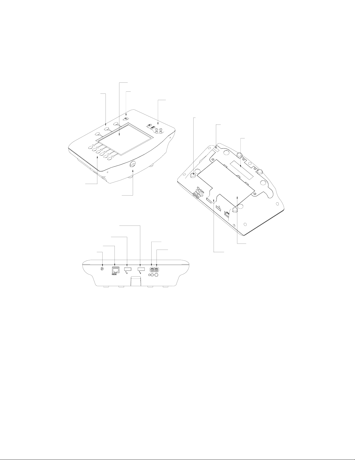
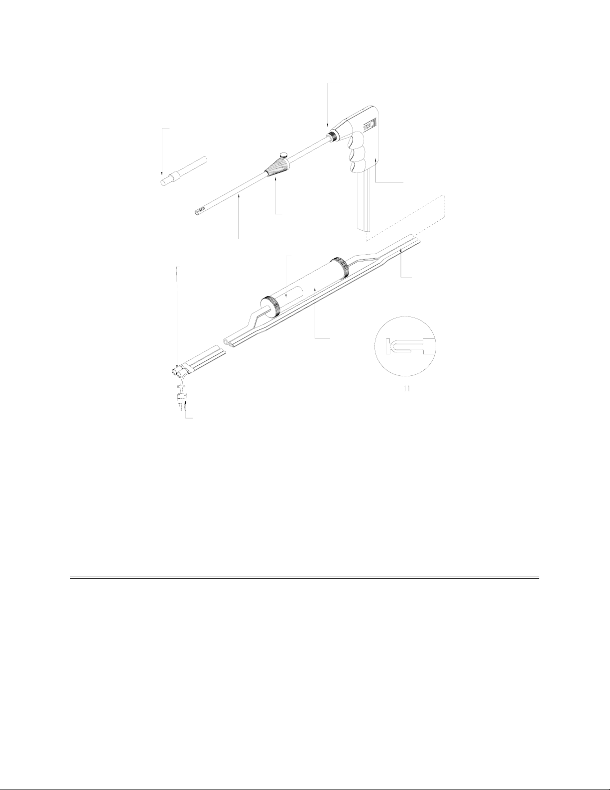
Key components of the CA-CALCTM combustion analyzer and sampling probe are identified in Figures 1 and 2 and
under section headings in the text that follows.
2
1
5
3
4
7
8
9
6
12
13
14
15
1. Label buttons 10. Battery cover
2. LCD display 11. Battery cover tab
3. On-Off button 12. Port for stack gas thermocouple probe
4. Control buttons 13. Port for combustion supply air thermocouple, type K
5. Icon buttons 14. RS232 serial port
6. CO diversion valve 15. Power connection
7. Magnets 16. Draft sample port
8. Vent 17. Gas sample port
9. Sensor cover
Figure 1: CA-C
16
17
ALC Combustion Analyzer Components
11
10
5
1
9
2
3
4
10
5
7
8
6
1. Sample tube retaining fitting 7. Tri-plex tubing
2. Probe handle 8. Water trap
3. Position collar 9. Emission Probe for NO2, SO2, with SS filter
4. SS sampling tube 10. Plastic filter
5. Sample and Draft connectors 11. Detail of standard probe tip
6. Thermocouple connector
Figure 2: CA-C
ALC Sampling Probe Components
The Gas Sensors
The CA-CALC analyzer holds up to four electrochemical gas sensors. Oxygen (O2) and hydrogen compensated
carbon monoxide [CO(H
Two of the following sensors can also be added: nitric oxide (NO), nitrogen dioxide (NO
and high concentration carbon monoxide (COhi). The gas sensors are found under the sensor cover identified in
Figure 1 above.
)] sensors are standard, included with all Series CA-6200 CA-CALC combustion analyzers.
2
), sulfur dioxide (SO2)
2
6 Series CA-6200 CA-CALC Combustion Analyzer

Optional Combustion Supply Air Thermocouple Probe
A measurement of the Combustion Supply air temperature is made using an optional thermocouple accessory probe
(TSI PN 3013003). This probe is connected to the supply air temperature port.
Combustion supply air temperature is an important value used in the determination of flue losses and efficiency.
On-Board Temperature Measurement
The CA-CALC analyzer uses an on-board resistance temperature detector (RTD) to provide the combustion supply
air temperature when no supply-air accessory probe is present.
Diaphragm Pump
The CA-CALC analyzer samples exhaust gases from the flue and delivers them to the electrochemical sensors using
a long-life diaphragm sampling pump.
Draft Sensor
A differential pressure transducer in the CA-CALC analyzer is used to measure draft pressure. The transducer has a
measurement range of ±30” of H
O (7.47 kPa).
2
Water Trap
The water trap shown in Figure 2 is used to remove moisture that collects in the sample tubing when combustion
gases are sampled. Water must be prevented from entering the instrument through the sample port. The water trap
uses two chambers and a hydrophobic coalescing filter to maximize water removal.
Stack Probe Thermocouple
The type K thermocouple probe extends through the SS sampling tube to its tip, where stack temperatures are
measured. The thermocouple probe measures temperatures up to 1800 degrees F.
The yellow thermocouple connector plugs into the stack thermocouple port (see Figure 1).
Emission Probe (Supplied with Models CA-6213 and CA-6215 )
An “Emission” gas sample probe (Model 801951) is required when NO2 and SO2 gases are measured. This gas
sampling probe has an internal liner (TFE), which does not absorb NO
a sintered stainless steel filter at the probe tip to reduce soot buildup in the sampling lines. Soot, combined with
moisture from condensation, readily absorbs NO
Emission probe slows the response of the temperature sensor.
Note: When making temperature measurements, maintain the position of the probe in the flue until the
temperature reading has stabilized. For faster temperature measurement, when determining combustion
efficiency, a Model 801940 Sampling Probe is recommended.
and SO2. Note that the sintered metal filter on the tip of the
2
and SO2 gases. The Emission Probe also has
2
Chapter 3. Component Identification 7
CO Diversion Valve
The CO diversion valve is used to divert high concentrations of carbon monoxide (>5000 ppm) away from the
hydrogen compensated CO sensor. High CO concentrations cause the sensor baseline value to shift upward.
Although the effect is temporary, it may take ten minutes or longer for the sensor to recover. A shift upward in the
sensor baseline means the CO sensor indicates a concentration that is higher than the true concentration.
Mounting Magnets
The CA-CALC combustion analyzer can be adhered to a flat metal surface using the magnets on the case bottom.
This orients the instrument for convenient viewing and button operation. When mounted in this way it is advisable
to use the optional strap/tether (see optional accessories) as a safety harness in case the instrument is pulled away
from the metal surface. Metal surface must not be hot.
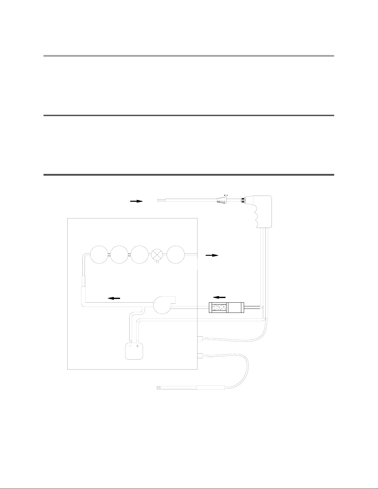
Schematic Representation of CA-CALC
Sampling Probe
Gas Sensors [S1 & S2; NO, NO
COhigh (optional))
O2
Orifice
Probe for Combustion
Air Temperature
(optional)
S1
Draft
Sensor
S2
CO Diversion
Valve
Pump
, SO2,
2
CO
Exhaust
Water Trap
Flue Gas
Temperature
Thermocouple
8 Series CA-6200 CA-CALC Combustion Analyzer
Chapter 4. Getting Started
Supplying Power
The CA-CALC
Quality alkaline batteries enable the instrument to operate for 24 hours. Use of the plug-in AC adapter conserves
battery life and can be substituted for batteries.
TM
portable combustion analyzer operates using 4 C-cell batteries or using the AC adapter provided.
Installing Batteries
Turn the combustion analyzer over and remove the battery cover by lifting up and
out on the battery cover tab shown to the right. Remove the old batteries.
Note: It is not necessary to remove the battery holder when removing or
installing batteries. Best results are obtained if the batteries opposite
the contact springs are removed first.
Install four new C-cell batteries, noting the battery orientation depicted on the base of the battery holder. Install
spring-side batteries first.
Connecting the AC Adapter
Find the supplied 7.2-volt AC Adapter included with the instrument. Connect the corresponding connector plugs to
the AC wall source and instrument power connection located on case bottom (see Figure 2). When using the power
supply, the batteries are bypassed.
Note: The CA-C
ALC analyzer does not charge rechargeable batteries.
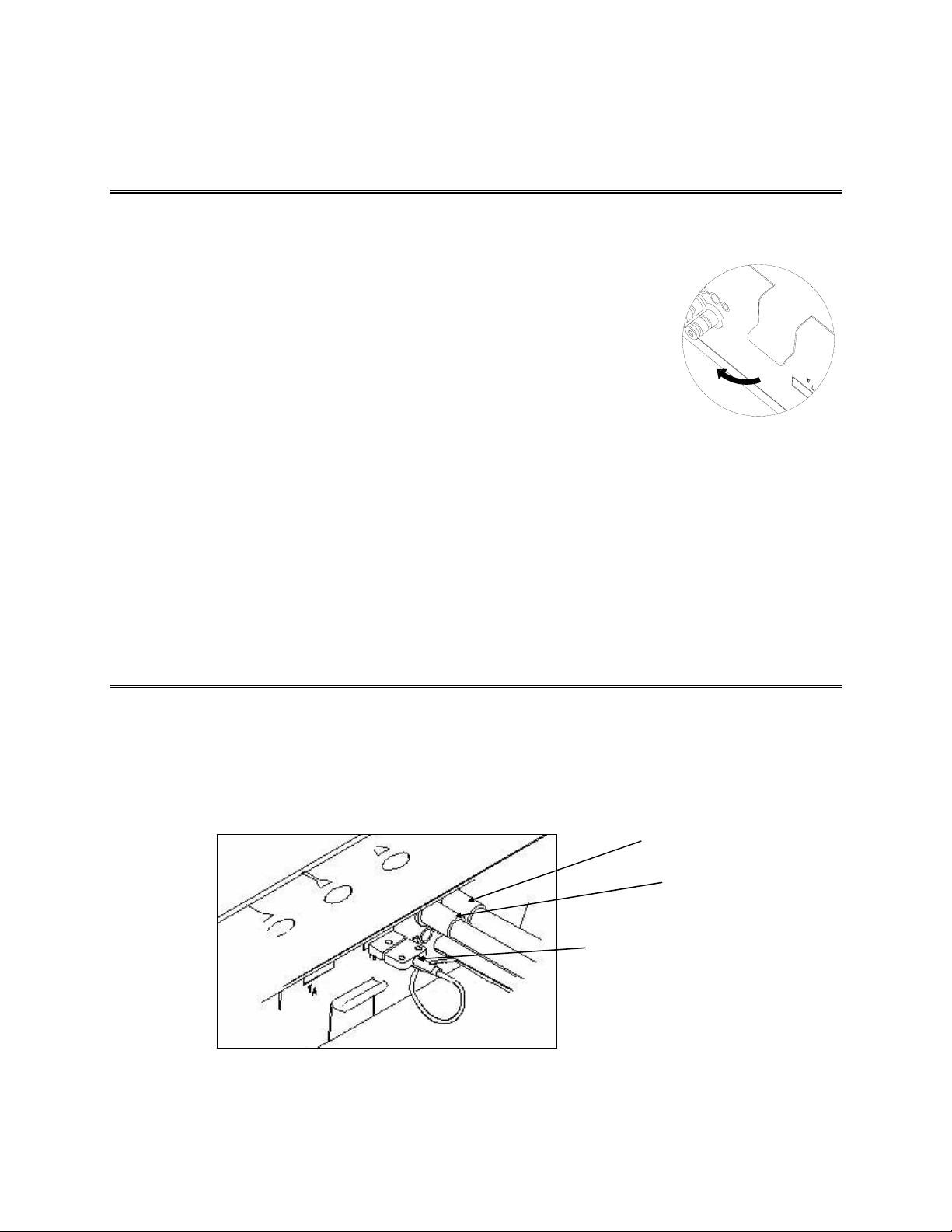
Connecting the Sampling Probe
The sampling probe depicted in Figure 2 is connected to the instrument by pushing the sample and draft connectors
over the bulkhead ports on the instrument. Refer to Figure 3 below showing the probe connection. Make sure the
connectors are pushed fully over the bulkhead ports. Finish the connection by plugging the yellow thermocouple
connector into the Stack temperature thermocouple port. The thermocouple plugs in only one way. Don’t force the
connector.
Thermocouple Connector
Figure 3: Sampling Probe Connection
Sample Connector
Draft Connector
9
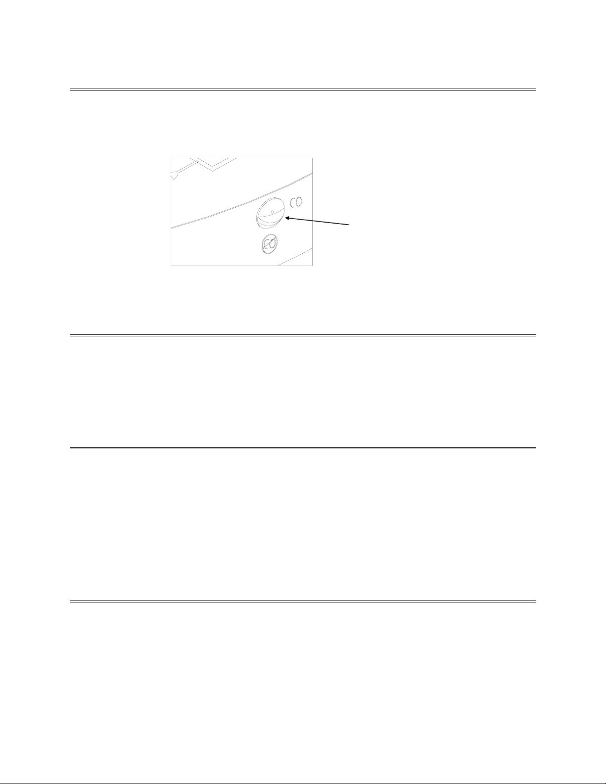
Setting CO Diversion Valve
Set the CO diversion in the orientation shown in the figure below. In this position, the valve is open, allowing gas to
flow to the CO sensor. Only under conditions where the CO level is very high (above 5000 ppm), should the valve
be closed. To close the valve, turn it 90 degrees counterclockwise.
Figure 4: Normal CO Diversion Valve Orientation
Normal Orientation for the
CO Diversion Valve
Connecting the Optional Combustion Supply Air Temperature Probe
An optional type K thermocouple probe (TSI PN 3013003) is used to measure the temperature of the air supplied to
the burner; the Combustion Supply air. When a probe is not used, the supply air temperature is measured using the
on-board resistance temperature detector (RTD). Connect the optional supply air thermocouple (see “Optional
Accessories”) to the supply air thermocouple port depicted in Figure 1. The thermocouple plugs in only one way.
Do not force the connector.
Connecting the Optional Portable Printer
Find the printer interface cable included with the Model 8925 portable printer. Connect the large 9-pin connector on
the cable to mating connector on the printer. Connect the opposite end to the instrument’s RS232 communications
and printer port. See Figure 1 for port location.
The printer and CA-C
different, the printer will print random characters, question marks or asterisks. Printer settings are described in the
printer manual, along with illustrations identifying the correct DIP-switch configuration. You will also need to set
the RS232 Device setting to Printer. To set the CA-C
“MENU Selections and Menu Items.”
ALC combustion analyzer have both been factory set for a baud rate of 1200. If baud rates are
ALC baud rate and device settings, refer to Chapter 6,
Connecting to a Computer
Use the optional computer interface cable, Model 8940, to transfer (download) data serially from the CA-CALC
analyzer to a computer. Connect the large 9-pin connector on the computer interface cable to the 9-pin serial
connector on your computer. Connect the opposite end to the instrument’s RS232 communications and printer port.
See Figure 1 for port location.
10 Series CA-6200 CA-CALC Combustion Analyzer
 Loading...