

TSI Incorporated Alnor LoFlo Balometer Owner's Manual
OWNER’S MANUAL
LoFlo
®
Balometer

LIMITATION OF WARRANTY AND LIABILITY
Seller warrants the goods sold hereunder, under
normal use and service as described in the operator's
manual, shall be free from defects in workmanship
and material for twenty-four (24) months, or the length
of time specified in the operator's manual, from the
date of shipment to the customer. This warranty
period is inclusive of any statutory warranty. This
limited warranty is subject to the following exclusions:
a. Hot-wire or hot-film sensors used with research
anemometers, and certain other components
when indicated in specifications, are warranted
for 90 days from the date of shipment.
b. Parts repaired or replaced as a result of repair
services are warranted to be free from defects in
workmanship and material, under normal use, for
90 days from the date of shipment.
c. Seller does not provide any warranty on finished
goods manufactured by others or on any fuses,
batteries or other consumable materials. Only the
original manufacturer's warranty applies.
d. Unless specifically authorized in a separate
writing by Seller, Seller makes no warranty with
respect to, and shall have no liability in
connection with, goods which are incorporated
into other products or equipment, or which are
modified by any person other than Seller.
TO THE EXTENT PERMITTED BY LAW, THE
EXCLUSIVE REMEDY OF THE USER OR BUYER,
AND THE LIMIT OF SELLER'S LIABILITY FOR ANY
AND ALL LOSSES, INJURIES, OR DAMAGES
CONCERNING THE GOODS (INCLUDING CLAIMS
BASED ON CONTRACT, NEGLIGENCE, TORT,
STRICT LIABILITY OR OTHERWISE) SHALL BE
THE RETURN OF GOODS TO SELLER AND THE
REFUND OF THE PURCHASE PRICE, OR, AT THE
OPTION OF SELLER, THE REPAIR OR
REPLACEMENT OF THE GOODS. IN NO EVENT
SHALL SELLER BE LIABLE FOR ANY SPECIAL,
CONSEQUENTIAL OR INCIDENTAL DAMAGES.
SELLER SHALL NOT BE RESPONSIBLE FOR
INSTALLATION, DISMANTLING OR
REINSTALLATION COSTS OR CHARGES. No
Action, regardless of form, may be brought against
Seller more than 12 months after a cause of action
has accrued. The goods returned under warranty to
Seller's factory shall be at Buyer's risk of loss, and will
be returned, if at all, at Seller's risk of loss.
Buyer and all users are deemed to have accepted this
LIMITATION OF WARRANTY AND LIABILITY, which
contains the complete and exclusive limited warranty
of Seller. This LIMITATION OF WARRANTY AND
LIABILITY may not be amended, modified or its terms
waived, except by writing signed by an Officer of
Seller.
The foregoing is IN LIEU OF all other warranties and
is subject to the LIMITATIONS stated herein. NO
OTHER EXPRESS OR IMPLIED WARRANTY OF
FITNESS FOR PARTICULAR PURPOSE OR
MERCHANTABILITY IS MADE.
Service Policy
Knowing that inoperative or defective instruments are
as detrimental to TSI as they are to our customers,
our service policy is designed to give prompt attention
to any problems. If any malfunction is discovered,
please contact your nearest sales office or
representative, or call Customer Service at
(800) 424-7427 (USA) and (1) 651-490-2811
(International).
.

1
TABLE OF CONTENTS
Section 1 General Description.........................................................2
Section 2 Theory of Operation........................................................2
Section 3 Safety...............................................................................3
Section 4 Instrument Setup and Storage..........................................3
Section 5 About the Instrument Display .........................................5
Section 6 Getting Started.................................................................6
Section 7 Detailed Operation ..........................................................6
Section 8 Troubleshooting ..............................................................9
Section 9 Maintenance..................................................................10
Section 10 Service Information.......................................................11
Appendix A Correction Factors for Standard
Flow Rate to Actual Flow Rate.....................................12
Appendix B Model 6200 LoFlo Balometer Field
Setting Instruction for User Programmable
Correction Factors.........................................................13
1

SECTION 1
General Description
The Alnor LoFlo Balometer is a compact instrument
that measures very low air flow rates in HVAC
systems. It measures from 10–500 cfm (17–850 m
4.7–236 l/s). The LoFlo Balometer displays standard air
volume rate when placed at supply or return diffusers,
registers, or grilles located on the ceiling, wall, or floor.
The LoFlo Balometer has a vent mechanism which
reduces the restriction of air flow caused by the
instrument. This unique venting system (patent
pending) allows the instrument to remain compact
while still measuring a wide range of volume rates. The
3
/h,
LoFlo Balometer should be used with the vents closed
at lower volume rates, but higher volume rates should
be measured with the vents open to minimize any
resistance effects. A 2-point measurement may be taken
to compensate for the resistance effect of the instrument
at higher volume rates.
The LoFlo Balometer is battery powered and may be
used with or without optional hoods. It weighs just over
6 pounds with the 2' x 2' hood, helping to reduce
worker fatigue.
SECTION 2
Theory of Operation: Capture Hoods
and Thermo-anemometry Sensing
As air exits a diffuser, it is captured in the hood or base
and directed over a manifold. The manifold averages
the velocity pressure and directs air over the sensors.
The velocity and temperature of the air passing through
the manifold are sensed, using a constant temperature
thermo-anemometer principle. The voltage output from
the sensor is then calibrated for the entire volume rate
passing through the LoFlo Balometer.
All capture hoods are susceptible to “odd” air flow
patterns. “Odd” could refer to any air flow pattern
different from the pattern where it was calibrated.
Substantial negative effects can be observed when
using a large hood on a small diffuser. For example,
using a 2' x 2' hood on a 10" x 10" diffuser. This creates
large recirculation regions on the sides of the fabric
hood and causes an “odd” air flow pattern as it passes
over the manifold. It is recommended to match the
hood closely to the size of the diffuser.
3
! NOTE: Throughout this manual, the units cfm, m
and l/s are used for simplicity. Note, however, that
the LoFlo Balometer actually reads in standard
cubic feet per minute (scfm), standard cubic meters
per hour (std. m
(std. l/s).
3
/h), or standard liters per second
/h
2

3
SECTION 3
Safety
When using the LoFlo Balometer to check air flow at
ceiling diffusers, make certain that you can safely raise
and hold the unit while making measurements. Be
especially careful when working on a ladder.
Observe all necessary precautions so that the unit does
not become caught in moving machinery or touch any
exposed electrical wiring.
SECTION 4
Instrument Setup and Storage
Hood Setup
1. Locate the four (4) aluminum channels for the
hood and position them into a square with the foam
facing up. Slide the “U” opening on the channel
end (Fig. 1) and corner bracket toward the brass
eyelets until you feel it latch.
2. Continue with the o ther two channels until you
have a square frame that is locked tightly in all
four corners.
The LoFlo Balometer is not designed for gas mixtures
other than air. Use with corrosive or other dangerous or
explosive gas mixtures is not recommended and is at
the user’s risk.
8. Locate the hood support rods. Extend the hood so
it is taut and insert one support rod onto the springloaded pin closest to you.
9. Push the support rod down and insert the top end
of the rod into the metal cup on the hood frame.
Fig 1.
10. Install the rod on the opposite side, then install the
last two rods.
Foam
3. Locate the hood for the frame size you have
assembled.
4. Position a corner seam of the hood onto the corner
of the frame. Stretch the nylon hood to an adjacent
corner until the hood corner meets the frame
corner.
5. Push the elastic cord into the channel along the
side of the frame.
6. Repeat steps 4 and 5 until the hood assembly is
complete and ready to mount onto the base.
7. Place hood on a table or clean floor with the base
inside the opening. Pull the hood over the base.
Rotate the hood assembly until the metal cups are
above the spring-loaded pins.
“U” Opening
Metal Cup
Figure 1
Hood Frame Channel
3
Intrument Storage
The hood and frame assemblies can be detached from
the instrument base and placed inside their own
carrying case without disassembly.
The LoFlo Balometer should always be turned off
before re-packing the instrument. If storing the LoFlo
Balometer for an extended period of time, remove the
batteries to prevent damage due to leakage.
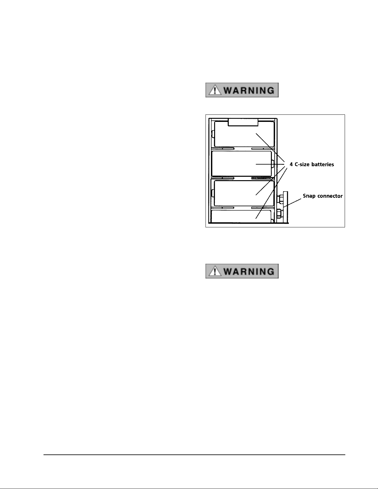
Battery Installation
To install the 4 C-size batteries that ship with the LoFlo
Balometer:
1. Make sure the LoFlo switch is off.
2. Remove the battery cover located on top of the
meter.
3. Slide the battery holder up until the snap connector
is exposed.
4. Disconnect the battery holder from the LoFlo
Balometer.
3. Reconnect the fully charged battery holder to the
LoFlo Balometer and slide battery holder into the
battery compartment.
4. Replace battery cover.
Do not try to charge
alkaline batteries.
5. Install the 4 C size batteries in the holder.
6. Reconnect the snap connector and slide the battery
holder into the battery compartment.
7. Replace battery cover.
To use and install rechargeable batteries:
! NOTE: As an alternative to alkaline batteries, four
Nickel Cadmium (NiCd) rechargeable batteries are
available from TSI for use in the LoFlo Balometer.
1. Connect the battery holder loaded with
rechargeable NiCd batteries to the charger and
charge for 12–14 hours.
2. Turn the LoFlo off.
Figure 2
Battery Holder
Do not use the
charger as a battery
substitute. Damage
to the instrument
will result.
4
SECTION 5
About the Instrument Display
This display is an analog display, simulated with 26
LCD segments to give the user the response of a
mechanical Balometer. It also displays an exact digital
number, using 3½ digit numeric section. The LCD has
indicators for supply, return, manual range, vent modes,
and low battery.
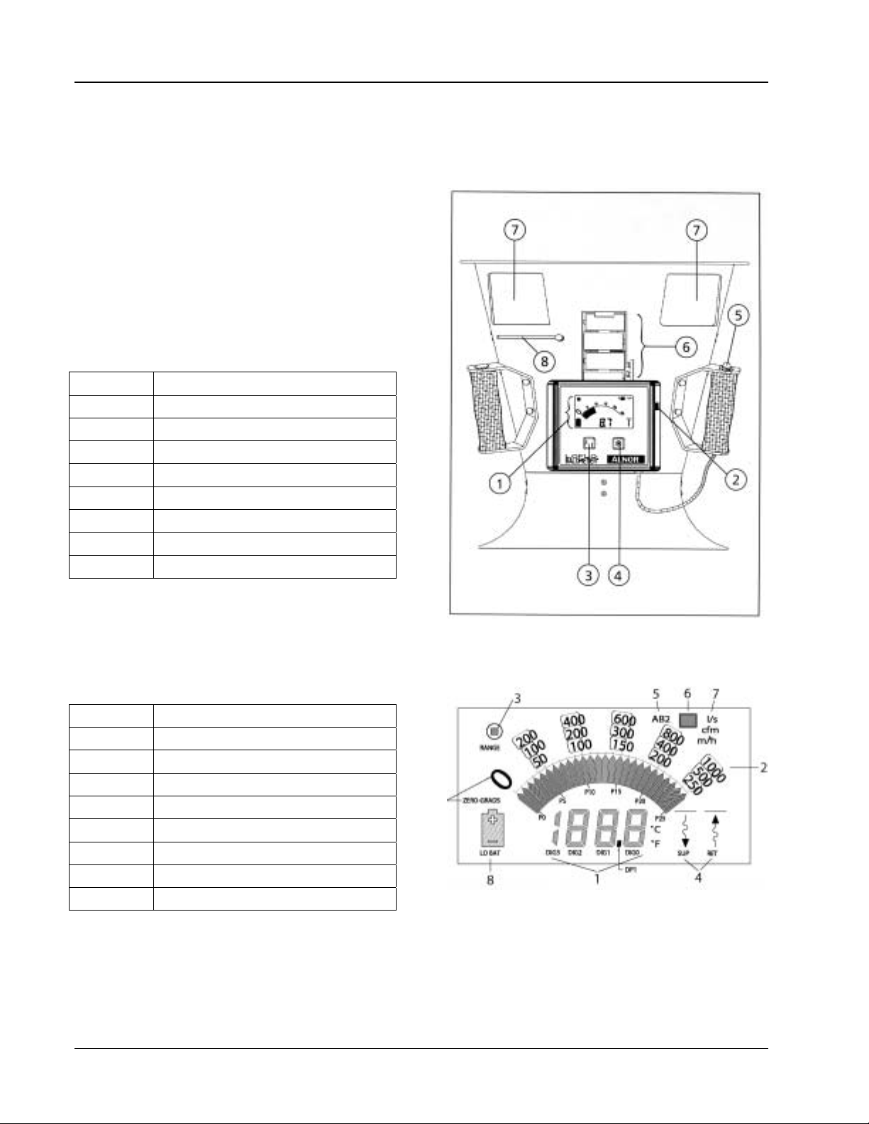
Figure 3 shows the front of the LoFlo Balometer.
Index No. Name
1 LCD
2 On/Off Switch
3 Supply/Return Button
4 Manual Range Button
5 Handle Button
6 Battery Holder
7 Vents
8 Vent Open/Close Slide
5
Figure 4 shows the LCD.
Index No. Name
1 Digital Readout
2 Simulated Analog Display
3 Manual Range Indicator
4 Supply/Return Indicator
5 2-Point Mode Indicator
6 Vent Indicator
7 Units Indicator
8 Low Battery Indicator
Figure 3
Front View of LoFlo Balometer
Figure 4
LoFlo Balometer LCD
5

SECTION 6
Getting Started
! NOTE: The instrument should be allowed to
stabilize to room conditions in order to achieve
specified accuracy.
1. If you are using a hood with the unit, assemble
the LoFlo Balometer as described in Section 4,
“Instrument Setup and Storage.”
2. Turn on the unit using the slide switch located on
the right side of the meter.
3. When turned on, the LoFlo Balometer displays
the vent closed indicator. Close the vent on the
base by turning the top baffle counter clockwise.
4. Select the proper mode for air flow direction,
supply or return.
5. Place the LoFlo over the diffuser or grille to be
measured.
SECTION 7
Detailed Operation
6. The auto range feature of the LoFlo Balometer
will choose the correct scale and display the
volume rate in the digital readout section. A quick
press on the handle switch will freeze the display.
7. Another quick press will unfreeze the display.
3
8. For volume rates above 150 cfm (255 m
l/s), it is recommended to use the vent open mode
to minimize air flow resistance effects. See
Section 7, “Detailed Operation.”
! NOTE: Make sure that there are no gaps between
the LoFlo and the surface around the diffuser or
grille. Also, make sure that your body or other
objects are not blocking or diverting the air flow
where the air is exiting (supply) or entering
(return). This will affect the reading.
/h, 71
Handle Button
In 1-point mode, the handle button will freeze the
digital reading and flash the value when it is pressed for
less than three seconds. When the handle button is
pressed for more than three seconds, it switches the
LoFlo Balometer between vent closed mode and vent
open mode.
In 2-point mode, the handle button cycles the
instrument through the 2-point measurement process.
See 2-point mode section for detail.
Auto/Manual Ranging Button
When turned on, the instrument is in auto-range mode.
The user can switch to manual range mode by pressing
the range button. The manual range indicator will
show. By pressing the range button, the meter display
switches to the next volume range. To return to autorange mode, press and hold the range switch until the
manual range indicator disappears.
Changing Measurement Units
To change measurement units:
1. Turn the instrument off.
2. Press and hold the supply/return button and switch
the instrument on at the same time.
3. The display will flash one of the three available
measurement units: cfm, m
4. Press and hold the supply/return button or the
range button to scroll through the measurement
units.
5. When the units you desire are displayed, switch the
instrument off.
6. When you turn the instrument on again, your
chosen units will be displayed.
3
/h, l/s.
6
Supply/Return Button
The LoFlo Balometer is in supply mode when turned
on. This is indicated on the display with the supply
indicator
. To take return air measurements, press the
supply/return button on the front of the meter. Return
air mode will be indicated on the display with the return
indicator
.
Significant errors may result if:
• Instrument is not in proper mode.
• Fabric hood is not used with vent open
mode.
Vent Closed/Vent Open Modes
When the instrument is turned on, it is in the vent
closed mode
the vents must be closed to take the measurement.
Close the vents by loosening the thumbscrew and
sliding the vent baffle to the fully closed position and
locking the vent in place again.
The vent open mode is indicated with the vent open
indicator on the LCD
the thumb screw and sliding the vent baffle to the fully
open position and locking it into place again. Then
press and hold the handle switch for more than 3
seconds to switch the LoFlo Balometer to the open vent
mode.
. When the vent closed indicator is on,
. Open the vents by loosening
7
3
10–150 cfm (17–255 m
! NOTE: In Vent Closed Mode, volume rates below
8 cfm (13 m
3
/h, 3.6 l/s) are displayed as 0; volume
rates above 517 cfm (879 m
/h, 4.7–71 l/s).
3
/hr, 244 l/s) are
displayed as Or.
Use Vent Open Mode for measurements between:
3
150–500 cfm (255–850 m
! NOTE: In Vent Open Mode, volume rates below
150 cfm (255 m
3
volume rates above 517 cfm (879 m
/h, 71–236 l/s)
/h, 71 l/s) are displayed as Ur;
3
/h, 244 l/s) are
displayed as Or.
2-Point Measurement Mode—Supply Only
To activate the 2-point measurement mode, turn the
instrument off. While pressing the handle button, turn
the instrument back on. The 2-point mode indicator will
show.
The 2-point measurement mode takes both vent open
and vent closed measurements to calculate a resistancecompensated volume flow rate.
The process starts with the vents closed and the display
showing the vent closed indicator.
1. Place the LoFlo Balometer over the diffuser to be
measured and press the handle switch once to take
the vent closed measurement.
2. The instrument stores that reading.
3. The display will now show the open vent indicator
and you should open the vents.
The vent open mode was developed for higher volume
rates on larger diffusers; the 2' x 2' or 650 mm x
650 mm hood should always be used with vent open
mode.
1-Point Measurement Mode
The default mode of the LoFlo Balometer is the 1-point
measurement mode. If you are in 2-point measurement
mode, simply turn the instrument off and turn back on.
The 1-point measurement mode is described in the
Getting Started section earlier in this manual. This is
the faster, simpler way to take measurements.
Use Vent Closed Mode for measurements between:
! NOTE: Make certain you are using a fabric hood
when in 2-point mode.
4. Again place the LoFlo Balometer over the diffuser
to be measured and press the handle switch to take
the vent open measurement.
5. The instrument calculates and displays the
compensated reading.
6. The numeric display will flash; press the handle
switch again and the instrument will display the
vent closed indicator. Close the vents.
7. Return to Step 1 to take another resistance
compensated reading.
! NOTE: Return to 1- point measurement mode at
any time by turning the power off and on.
7

When “–––” is displayed at the last step of the 2-point mode, the calculation for the resistance effect cannot be made. It
can be caused by any of the conditions listed here.
Condition Reason
The vent closed or vent open measurement is less than 150
cfm (70 l/s, 255 m
The vent closed or vent open measurement is greater than
500 cfm (235 l/s, 850 m
The vent open measurement minus the vent closed
measurement is too small (< 0).
3
/h).
3
/h).
• Calculations are not made at the low end since the
effect is small and can generally be neglected. Use 1point mode.
• Calculations are not made beyond the calibrated range.
Use the Standard or Electronic Balometer (Range: 50–
2000 cfm), or perform a traverse of the system instead.
• A mistake has occured in the process. Repeat the two-
point measurement.
• The resistance effect is small and was overwhelmed
by natural fluctuations. Use single-point mode.
The vent open measurement minus the vent closed
measurement is too large.
• A mistake has occurred in the process. The vent may
not have been open for the open vent measurement.
Repeat the two-point measurement.
• The effect is beyond the range of the compensation
equation. Perform a traverse of the system instead.
! NOTE: The display will also show “–––” when the return mode is selected. The 2-point measurement mode is for
supply only.
8

9
SECTION 8
Troubleshooting
Symptom Possible Cause and Corrective Action
Meter does not turn on.
Meter reading lower than expected.
• Battery holder snap connector not connected. Connect
battery holder to instrument.
• Batteries may be discharged. Charge or replace them.
• Switch failure, wiring failure, or circuit failure. Call
TSI.
• Wrong vent mode chosen. Choose correct vent mode,
open or closed.
• Wrong air direction mode chosen. Choose correct
direction, supply or return.
• Back pressure effects could be significant. Use 2-
point measurement mode.
• Hood frame not sealing properly around diffuser or
grill. Press hood evenly against diffuser.
Meter reading higher than expected.
Meter not at zero at zero flow.
Meter displays Er.
Handle button not working.
• Odd air flow pattern present. Perform traverse and use
proportional balancing.
• Hood torn. Replace, or repair tear with duct tape or
other non-porous material.
• Meter out of calibration. Call TSI.
• Damage to manifold. Call TSI.
• Wrong vent mode chosen. Choose correct vent mode,
open or closed.
• Wrong air direction mode chosen. Choose correct
direction, supply or return.
• Odd air flow pattern present. Perform traverse and use
proportional balancing.
• Meter out of calibration. Call TSI.
• Instrument not at room temperature. Allow instrument
to acclimate before turning on the power.
• The LoFlo is reading real room air currents. Place on
floor with a piece of cardboard over the top to
determine if it is measuring real air currents.
• Meter out of calibration. Call TSI.
• Self test failed. Call TSI.
• Call TSI.
9

SECTION 9
Maintenance
Hoods
Hoods may be cleaned in cool water with a mild
detergent.
Sensing Manifold
The manifold should be checked visually before using
to be certain that the sensing holes have not become
clogged with dirt or dust particles. Do not immerse the
manifold in water. It is recommended that cleaning be
done with extreme care with the manifold in place. Do
not use highly compressed air to clean the manifold
tubes.
Calibration
It is recommended that your LoFlo Balometer be
returned to the factory once a year for a calibration
check. When shipping the LoFlo Balometer for factory
calibration, pack it carefully, and follow the
Instructions for Return in this manual.
Vent Operation
If the vent becomes difficult to operate, remove both
thumbscrews from the vent mechanism and spray the
contacting surfaces with silicone spray lubricant. Wipe
off excess and reassemble vent mechanism.
Performance Check
If the calibration is to be checked, the best way is to use
a reference flow standard more accurate than the LoFlo
Balometer. Flow standards that may be used for this
purpose include orifice plates, venturis, nozzles, and
laminar flow elements. These devices require accurate
differential pressure, barometric pressure, and
temperature reading instruments to measure either
actual or standard volume rate.
If the LoFlo Balometer is checked against a velocity
instrument such as a pitot probe/manometer or thermoanemometer, there may be errors. If a velocity standard
is used, the average velocity must be obtained by taking
a traverse.* The accuracy of the traverse is dependent
on the flow uniformity, the number of readings taken,
the accuracy of the velocity instrument, and operator
expertise. This average velocity reading must then be
multiplied by the area over which the traverse was
taken.
Finally, air flow instrumentation is dependent on
environmental conditions such as temperature,
atmospheric pressure, humidity, and even turbulence.
These conditions can have very different effects on
various instrument types. Caution must be exercised
when making comparisons.
*A traverse is a set of velocity readings taken in a prescribed
pattern which will provide an overall velocity value when
averaged together. Any of the Alnor velocity measuring
instruments can be used for this purpose.
10

11
SECTION 10
Service Information
Service and Repair
Please return your Product Registration Card
immediately. This allows us to send you service
reminders, special offers, and important information
about your product.
Before sending your instrument for calibration or
repair, you should call TSI Customer Service. The
Service Department will provide you with the cost of
service or calibration, Return Material Authorization
(RMA) number, and shipping instructions.
Please have the following information available when
you call:
! Owner’s name, address, and phone number
! Billing address, if different and applicable
! Instrument name or model
! Serial number
! Date of purchase
! Where purchased
TSI recommends that you keep a “calibration log” and
keep all records of service on your instrument.
Instructions for Return
Include the Purchase Order showing instrument model
number, cost of service and/or calibration, and the
RMA number. Mark the outside of the shipping
container with the RMA number. This will expedite
processing of your instrument when we receive it.
Damaged in Transit
All orders are carefully packed for shipment. On
receipt, if the shipping container appears to have been
damaged during shipment, the instrument should be
thoroughly inspected. The delivering carrier’s papers
should be signed noting the apparent damage. DO NOT
DISCARD THE BOX.
If the instrument itself has been damaged, a claim
should be promptly filed against the carrier by the
customer. The selling agent will assist the customer by
supplying all pertinent shipping information; however,
the claim must be filed by the insured. If the instrument
is damaged beyond use, a new order should be placed
with TSI while awaiting reimbursement from the
carrier for the damaged instrument.
Call TSI directly for assistance if necessary.
Send the instrument prepaid. Securely package your
instrument in a strong container surrounded by at least
two inches (5 cm) of suitable shock-absorbing material.
11

APPENDIX A
Correction Factors for Standard Flow Rate to Actual Flow Rate
The LoFlo Balometer measures standard volumetric
flow rate. Standard flow is defined as the flow rate at
standard conditions, 70°F (21.1°C) and 14.7 psia
(29.92 inHg, 760 mmHg). Actual flow rate is the true
volumetric rate of air at the local temperature and
barometric pressure. If you desire standard flow rate,
use the displayed reading. However, if the actual flow
rate is desired, use the information below.
To correct the standard flow rate to actual flow rate use
the equation below.
V
= V
act
V
= Actual flow rate
act
V
= Standard flow rate (this is displayed by
std
std
x CF
the instrument)
T
= Actual Temperature
act
ρ
= Actual barometric pressure
act
3
ρ
= Standard density 0.075 lb/ft
std
(at 70°F and 14.7 psia)
ρa = Actual density in lb/ft
3
CF = ρ
(Correction Factor)
std/ρa
Using the equations or chart below, you can bypass the
full density calculation.
Calculations in imperial units
CF = (14.7/ ρ
Where ρ
is in psia and T
act
)*(460+ T
act
act
is in °F
act
)/530
Calculations in imperial units
CF = (29.92/ ρ
Where ρ
is in inHg and T
act
)*(460+ T
act
act
is in °F
act
)/530
Calculations in metric units
CF = (760/ ρ
Where ρ
act
)*(273.15+ T
act
is in mmHg and T
act
is in °C
act
)/294.25
For your convenience, we have made a chart for
determining the correction factor given temperature and
pressure.
! NOTE: The atmospheric pressure as reported by
the National Weather Service is corrected to sea
level and cannot be used if measurements are not at
sea level.
12
 Loading...