

TSI Incorporated Alnor Balometer Jr. Owner's Manual

OWNER’S MANUAL
®
Balometer Jr.

LIMITATION
OF WARRANTY AND LIABILITY
Seller warrants the goods sold hereunder, under normal use and service as described in the operator's manual, shall be
free from defects in workmanship and material for twelve (12) months, or the length of time specified in the operator's
manual, from the date of shipment to the customer. This warranty period is inclusive of any statutory warranty. This
limited warranty is subject to the following exclusions:
a. Hot-wire or hot-film sensors used with research anemometers, and certain other components when indicated in
specifications, are warranted for 90 days from the date of shipment.
b. Parts repaired or replaced as a result of repair services are warranted to be free from defects in workmanship and
material, under normal use, for 90 days from the date of shipment.
c. Seller does not provide any warranty on finished goods manufactured by others or on any fuses, batteries or other
consumable materials. Only the original manufacturer's warranty applies.
d. Unless specifically authorized in a separate writing by Seller, Seller makes no warranty with respect to, and shall have
no liability in connection with, goods which are incorporated into other products or equipment, or which are modified
by any person other than Seller.
The foregoing is IN LIEU OF all other warranties and is subject to the LIMITATIONS stated herein. NO OTHER EXPRESS
OR IMPLIED WARRANTY OF FITNESS FOR PARTICULAR PURPOSE OR MERCHANTABILITY IS MADE.
TO THE EXTENT PERMITTED BY LAW, THE EXCLUSIVE REMEDY OF THE USER OR BUYER, AND THE LIMIT OF
SELLER'S LIABILITY FOR ANY AND ALL LOSSES, INJURIES, OR DAMAGES CONCERNING THE GOODS
(INCLUDING CLAIMS BASED ON CONTRACT, NEGLIGENCE, TORT, STRICT LIABILITY OR OTHERWISE) SHALL
BE THE RETURN OF GOODS TO SELLER AND THE REFUND OF THE PURCHASE PRICE, OR, AT THE OPTION OF
SELLER, THE REPAIR OR REPLACEMENT OF THE GOODS. IN NO EVENT SHALL SELLER BE LIABLE FOR ANY
SPECIAL, CONSEQUENTIAL OR INCIDENTAL DAMAGES. SELLER SHALL NOT BE RESPONSIBLE FOR
INSTALLATION, DISMANTLING OR REINSTALLATION COSTS OR CHARGES. No Action, regardless of form, may be
brought against Seller more than 12 months after a cause of action has accrued. The goods returned under warranty to
Seller's factory shall be at Buyer's risk of loss, and will be returned, if at all, at Seller's risk of loss.
Buyer and all users are deemed to have accepted this LIMITATION OF WARRANTY AND LIABILITY, which contains the
complete and exclusive limited warranty of Seller. This LIMITATION OF WARRANTY AND LIABILITY may not be
amended, modified or its terms waived, except by writing signed by an Officer of Seller.
Service Policy
Knowing that inoperative or defective instruments are as detrimental to TSI as they are to our customers, our service
policy is designed to give prompt attention to any problems. If any malfunction is discovered, please contact your nearest
sales office or representative, or call Customer Service at (800) 424-7427 (USA) and (1) 651-490-2811 (International).
.

BALOMETER JR.
SECTION 1:
SECTION II:
SECTION III:
ENGLISH ....................................................................1
SPANISH ..................................................................25
FRENCH...................................................................53


TABLE
OF
CONTENTS
General
Using the Balometer Jr. Safely ............................................. 3
Preparation for
1.
2a. Setup of 2' x 2'
2b. Setup of 16" x 16"
3. Attaching Hood to Base ................................................... 5
4. Hood Support
5. Handle
6. LoFlow
Operation
Step by Step
Repacking
Performance Check ............................................................. 13
Calibration
General .............................................................................. 14
Equipment Required .......................................................... 14
Preparation.........................................................................
Calibration
Exchange of Calibrated
Appendix A: Theory of
Appendix B: Maintenance and Troubleshooting .............. 18
Maintenance.......................................................................
Troubleshooting .................................................................
Appendix C: Correction Factors for
Non-Standard
Repair
Instructions for
Ownership/Calibration Log ................................................. 23
Description
Unpacking ........................................................................
Attachment...........................................................
Adapter
................................................................................ 8
............................................................................. 12
Procedure
.......................................................................... 14
Hoods
Static
Manifold..........................................................................
Zero
Calibration
............................................................................. 18
Electricity
Adjustment
Information
............................................................... 2
Use
................................................................ 4
Hood
...................................................... 4
Hood
................................................. 4
System
................................................................ 7
Operation
.............................................................. 18
...................................................................... 18
Conditions
...............................................................
Return
...................................................... 6
...................................................... 11
..........................................................
Module
Operation
............................................................. 18
....................................................
........................................................
......................................... 15
.......................................
19
21
22
4
7
14
14
16
18
18
20
GENERAL
DESCRIPTION
The Alnor Balometer Jr. is designed to assist you in making rapid and
accurate measurements of air flow in heating, ventilating and air
conditioning systems. The Balometer Jr. directly reads average standard
air flow rate, for either supply or return diffusers, on the ceiling, wall or
floor. The use of this instrument eliminates the need for multipoint
velocity traverses, the resulting
as the use of K factors.
In use, air to be measured is captured by the hood assembly and then
directed past a square manifold which senses flow at 16 points. The
manifold is connected through the range selector to an Alnor Velometer
Jr. The meter is available in traditional units (cubic feet per minute
(cfm)*), or either of two metric units: cubic meters per hours (cmh),* or
liters per second (l/s).* The Balometer Jr. is capable of reading flows up
to 1400 cfm (2400 cmh, 660 l/s). The system is designed so that air flow
is sensed at either supply or return diffusers with equal accuracy.
A single knob to select both flow direction and range provides
control
ranges of 100 to 600, and 400 to 1400 cfm (200 to 1000, and 800 to 2400
cmh; 50 to 290, and 200 to 660 l/s). A LoFlow range is also available
of the Balometer Jr. for either supply or return diffusers on
which allows the instrument to read in the range of 0 to 200 cfm (0 to
340 cmh, 0 to 95 l/s) by using the included LoFlow adapter screen.
For increased flexibility, an optional 16" x 16" hood is available for
work with small diffusers or where the standard 2' x 2' hood will not
conveniently fit.
*Throughout this manual, the units cfm, cmh and l/s are used for simplicity. Note,
however, that the Balometer Jr. actually reads in standard cubic feet per minute (scfm),
standard cubic meters per hour (scmh), or standard liters per second (std. l/s). See the
Specifications section for more information.
averaging and
area calculations, as well
you
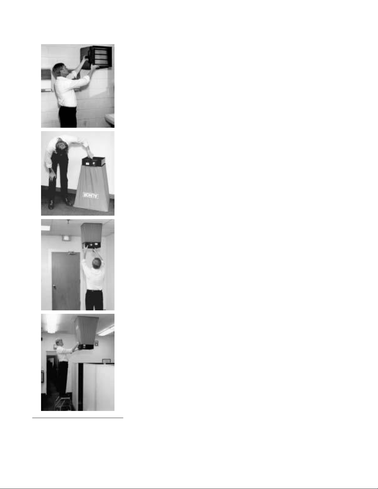
Figure 1: Typical usage
2

USING THE BALOMETER JR. SAFELY
When using the Balometer Jr. to check air flow at ceiling diffusers, make
certain that you can safely raise and hold the unit while making
measurements especially when working on a ladder.
Observe all necessary precautions so that the unit does not
caught
in moving machinery.
becom
e
The Balometer Jr. is not designed for gas mixtures other than air. Use
with corrosive or other dangerous or explosive gas mixtures is not
recommended, and is at the user’s risk.
Due to its size and shape, care should be taken when carrying the
assembled instrument from place to place so that it does not accidentally
bump into people or objects.
Special nylon material is used to manufacture the Balometer Jr. hoods
because of its impermeability and toughness. However, precautions
should be used so that it is not ripped by accidental contact with sharp
objects.
When the instrument is stored or otherwise not being used to
readings,
be certain to protect the meter movement by switching the
take
range selector to the OFF position.
The air flow sensing manifold can be damaged if subjected to excessive
stress. It is not repairable. Any air flow other than through the calibrated
sensing holes (even hairline cracks) will affect instrument accuracy.
Special manifold mounting springs are designed to cushion the assembly
and allow for some deformation of the base without affecting accuracy.
These springs should not be removed or altered in any way.
3

Figure 2:
Assembly of 16” x 16” frame top
4
PREPARATION
FOR USE
1. Unpacking
Before removing any parts from the carrying case, the arrangement of
various
items should be noted so that repacking can be done easily.
Depending on prior usage, either the 2' x 2' hood or the optional 16" x
16" hood may already be attached to the instrument base. If the entire
unit is to be lifted out as an assembly, caution must be exercised to
assure that the pieces do not separate, since dropping the instrument may
cause damage.
If your instrument was ordered with the optional 16" x 16" hood, it may
have been shipped in a separate carton. However, room has been set
aside in the instrument carrying case to store it when not in use. See
Repacking on page 12 for information.
2a. Setup of 2' x 2' Hood
Carefully remove the hood assembly from the case and unfold the hood
from around the frame. The frame itself is completely assembled, but
folded for storage. After the hood has been attached to the base (see
paragraph 3 on page 5), the assembly can be unfolded and deployed as
the hood is raised and attached to the hood support system (see page 6).
Proceed to step
3.
2b. Setup of 16" x 16" Hood
If the optional 16" x 16" hood is to be assembled, first locate the two ―L‖
shaped frame top sections packed to the left of the instrument base in the
carrying case. These sections are held together by an eyelet and slot
arrangement which mates with a similar eyelet and slot on the other
section. These pieces can be slid together, and are self locking by means
of a retention spring. For reference, the direction of sliding is marked by
an arrow on the appropriate corners of the frame sections. The assembled
frame should be square and solid. See Figure 2 for additional detail.
Now install the 16" x 16" hood to the frame top. This is most easily
accomplished by first stretching the hood around two corners of the
frame, and then pulling the hood into position around the other corners.
Make sure that the hood seams are located at the corners of the frame.
Finally, press the elastic
the frame. Assembly of the 16" x 16" hood is now complete.
cord
into the channel along each of the sides of
the
3. Attaching Hood to Base
If the hood size which is to be used is already attached to the base,
proceed to step 4.
First remove the hood which won’t be used by gently pulling the elastic
cord at the bottom of the hood out of its channel, working your way all
around
in the
the base.
When the hood is clear, carefully roll it up and place it
carrying case
to protect it from damage.
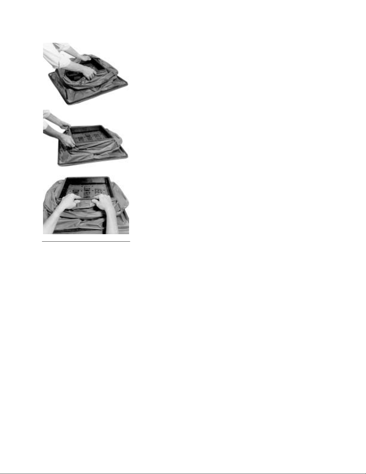
Next, attach the bottom of the hood which will be used to the base. This
is most easily accomplished by first stretching the hood around two
corners of the base, and then pulling the hood into position around the
other corners, keeping the hood seams in alignment with the corners of
the frame. Once this is done, the cord can be pressed into the channel to
keep the hood firmly attached and prevent air leaks. See Figure 3 for
details.
Figure 3:
Assembly of hood to base
5
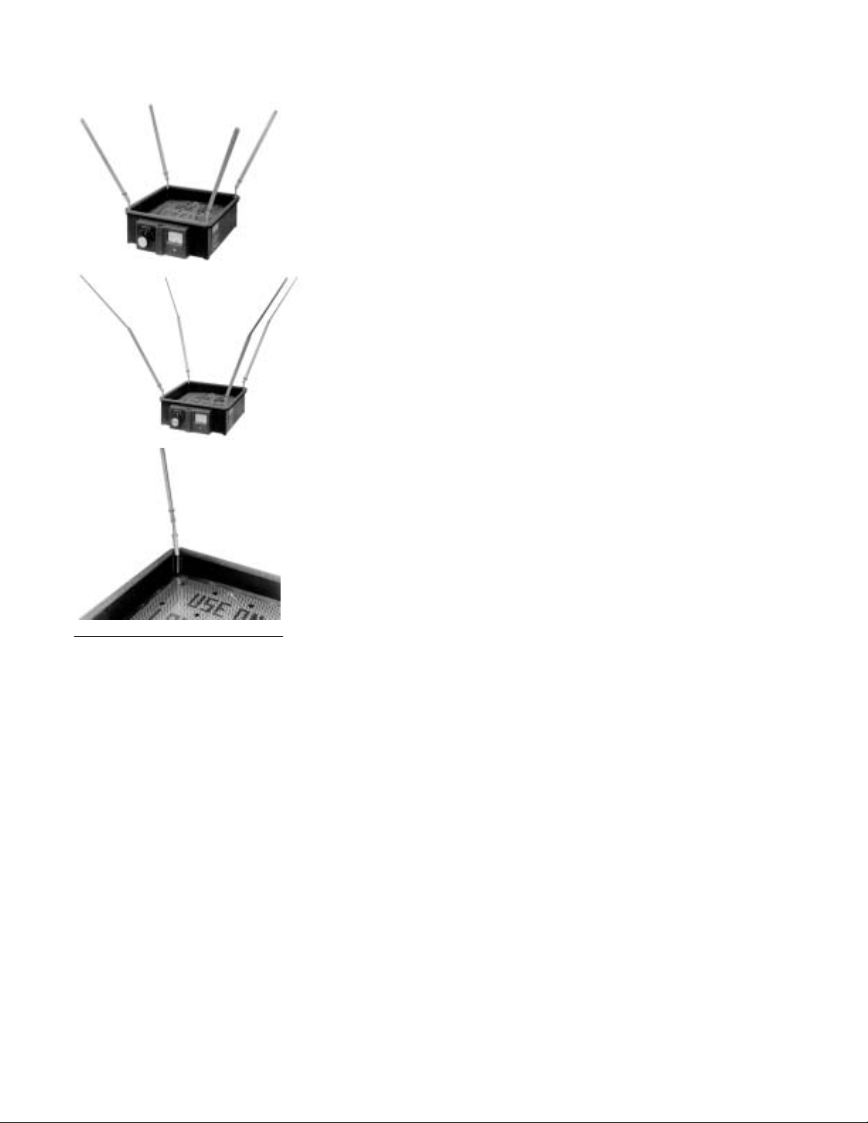
4. Hood Support System
Locate the four hood support rods which are packed behind the
instrument base in the carrying case. Insert one rod in each corner of the
base by pressing the round end of the rod into the square hole at the
inside base corner until the lip on the top of the round section is stopped
by the base. See Figure 4.
If the 16" x 16" hood is to be used, arrange the support rods so that the
tip of each rod is pointing away from the center of the base. See Figure 4.
If the 2' x 2' hood is to be used, the support rod must be extended to full
length. This is accomplished by pushing the retainer toward the base of
the support rod so that the end of the solid square extension is released
from the inside of the U-shaped section of the support rod assembly, and
is free to pivot on the hinge near the top of the U-shaped section. After
all the rods in all four corners are extended, they should be arranged so
that the open section of the U-channel is facing toward the center of the
base, and the tip of each rod is pointing away from the center of the base.
See Figure 4.
Once the support rods are properly located, the hood can be raised and
the
end
of the support rods inserted into the corners of the hood frame.
Proper tautness is achieved by the spring mechanism in the base of the
support rods.
Figure 4: Installation of
hood support system
6

Figure 5:
Handle location and installation
Figure 6: Installation of
LoFlow screen
5. Handle Attachment
Determine from the work to be done which handle arrangement will be
most convenient to use. Generally, if you are working from the floor, the
handle location near the bottom of the instrument will be most
convenient, while ladder work will be easiest with the handle installed on
the top of the range selector housing. Installation is accomplished by
simply turning the handle into
the threads
at either the top or bottom of
the range selector housing. Make sure that the handle is secure before
using. See Figure 5.
6. LoFlow Adapter
The LoFlow adapter screen can be used for measuring air volumes below
200 cfm (340 cmh, 95 l/s), but is strongly recommended for use only
when measuring very low flows, below 125 cfm (200 cmh, 60 l/s).
The LoFlow adapter is inserted by carefully pushing it into position
against the manifold on the side which the air will enter. (For example, if
the air will move through the hood to the base of the instrument, the
adapter goes on the ―hood‖ side of the manifold.) It is necessary that the
adapter be in very close
1
/16" may cause reading errors. Take care not to distort the manifold
contact with
the manifold. Gaps of more that
mounting springs or the adapter during installation or removal. See
Figure 6.
Do not forget to remove the adapter when the range selector is set to
either the medium or high range. The LoFlow adapter is not required
unless measurements of less than 100 cfm (200 cmh) are to be made. It is
strongly recommended that the adapter be used only when measuring
very low flows (up to 125 cfm, 200 cmh, 60 l/s).
This completes the assembly of the instrument. Proceed to the Operation
section for step by step instructions.
7

OPERATION
The operating controls for the Balometer Jr. are located on the front of the
instrument. These controls along with instrument features are illustrated
in Figures 7 and 8. A description of these controls and features is
provided in Tables 1 and 2.
8
Figure 7: Instrument controls and features—front view
(1) Foam Gasket
(2) Hood (2’ x 2’ shown)
(3) Handle (shown in top
position)
(7) Range Selector Switch
(8) Bezel
(5) Velometer Jr. Meter
(6) Zero Adjustment
(4) Lower Handle Position

Index No.
Name
Description
1
Foam Gasket
This gasket is used to provide a good air
seal between the top of the hood and the
diffuser.
2
Hood
The hood captures the air and directs it
toward the manifold.
3
Handle (top
position)
Intended for use when the Balometer Jr. is
used in conjunction with a ladder. Allows
for easy one-hand support of unit.
4
Lower Handle
Position
Intended for use when the Balometer Jr. is
used without the aid of a ladder. Extended
reach allows easy access to many ceiling
diffusers while standing on floor.
5
Velometer Jr.
Meter
The meter is calibrated to provide flow
readings in either cubic feet per minute or
cubic meters per hour. Separate scales
corresponding to the position of the range
selector are provided.
6
Zero
Adjustment
Rotating this screw allows the meter to be
set at zero. This adjustment should only be
made with the range selector set to OFF and
with no airflow past the manifold.
7
Range Selector
Switch
The 7-position switch is used to select the
required flow range and operating mode
(supply or return). The OFF position
prevents flow from passing through the
meter.
8
Bezel
Covers range selector and meter system.
Table 1: Instrument controls and features description—front view
9

Index No.
Name
Description
1
Support Arms
These arms are used to support the hood.
They can be removed and folded for
packing.
2
Manifold
This plastic assembly is used to produce an
average of the air flow at the 16 intake and
exhaust points.
3
Manifold
Springs
These springs are used to hold the manifold
in position and absorb shocks during
transportation.
4
LoFlow
Adapter
Used for measuring low air volumes. The
screen should be placed against manifold
on side from which the air is entering.
Screen covers entire manifold; cut-away
view is for clarity only.
Figure 8: Instrument features—top view
(1) Support Arms
(2) Manifold
(3) Manifold Springs
(4) LoFlow Adapter
(Cut-away view)
10
Table 2: Instrument features—top view

Step By Step Operation
If the instrument has been stored at a temperature below 68°F (20°C) or
higher than 86°F (30°C) it should be allowed to stabilize at room
conditions (68°F to 86°F) in order to achieve specified accuracy.
1. Assemble the Balometer Jr. as described in the Preparation for Use
section of this manual.
2. Check the Velometer Jr. for zero adjustment by setting the range
selector to the 0 (OFF) position and verifying that the meter reads
zero. If
that the pointer
continue to read zero (within one division) regardless of how the unit
is
used.
3. Set the range selector to the highest range in the desired direction,
supply or return.
4. Bring the Balometer Jr. into contact with the perimeter of the diffuser
or grill to be measured. To assure maximum accuracy, the foam
gasket along the top of the frame must be firmly in contact with the
surface all around the opening. Take care to ensure that your body or
other material is not accidentally affecting the reading by blocking or
diverting the air flow at either the air entry or exit sides.
When using the Balometer Jr. to check air flow at ceiling diffusers,
make certain you can safely raise and hold the unit while making
measurement.
ladder. Make sure that the unit cannot be caught in moving
machinery.
5. If the reading is found to be below the full scale of the next lower
scale, the range selector may be switched to the next lower scale.
If the lowest (blue) scale is used, the Lo-Flow adapter screen must
be installed. See Preparation for Use section.
6. The reading from the Balometer Jr. is in cubic feet per minute or
cubic meters per hour, referenced to standard conditions of air
pressure and temperature (scfm or scmh). These standard conditions
are 70°F and 29.92 inches of mercury (21°C and 760 mm Hg). To
determine the true volume flow rate, multiply by the correction
factor shown in Figure 11. The correction factor is based on the static
pressure and air temperature at the manifold.
7. The additional system back pressure generated by the Balometer Jr.
may affect the output of an individual diffuser. Depending on system
design and balancing method, this may or may not be important.
When proportionally balancing a system of similar outlets, this is not
usually an important factor. If system design or other factors require
adjustment, Figure 12 is
necessary, use
held,
it is best to zero the meter in the position in which it will be
a small screwdriver to adjust the zero screw so
reads zero.
Although the meter will typically
This is especially important when working on a
included for
your reference.
the
11
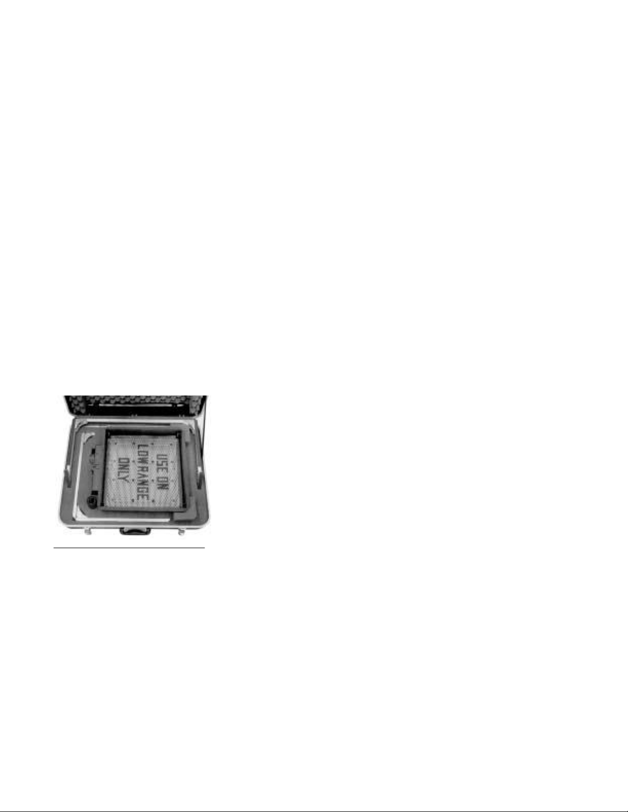
Figure 9: Location of unit in
carrying case
12
REPACKING
The Balometer Jr. can be stored in the carrying case with either the 2' x 2'
or the optional 16" x 16" hood attached. The 16" x 16" hood may be
stored fully assembled, while the frame for the 2' x 2' hood must be
folded in half prior to storage. First, remove the handle by unscrewing it
from the top or bottom of the range selector/meter assembly. Store the
handle in its pocket on the left side of the carrying case.
Next, remove the hood support rods by gently pressing down on the rod
to compress the spring in the lower tube assembly, and release it from the
corner of the hood frame. Each of the four rods should be removed from
the base by gently pulling upward on the lower U-section until the lower
tube assembly is
free
from the square section on the base. The top solid
section of the rod should now be folded into the U-section if it is not
already placed there. This is accomplished by pushing the retainer
toward the end of the U-channel, swinging the center rod into the Uchannel, and then pushing the retainer back so that it holds the rod in
place.
Note: Use care not to pinch fingers when swinging rod closed. After all
four rods are closed, they should be placed in their pocket, at the rear of
the carrying case. The LoFlow adapter screen is simply pressed into
place on the top side of the base to secure it.
If storing the base with the 2' x 2' hood in place, the next step is to fold
the frame top. Fold the frame in half at its hinge points, being careful not
to pinch the hood material, and then wrap the material around the folded
frame assembly. The instrument base can now be placed in the case
(aligned so that range selector and meter fit into proper cut-out on left
side). The frame and hood can be placed around the sides and back so
that the short center sections fit into the pockets on the sides of the case.
See Figure 9.
If storing the base with the 16" x 16" hood in place, first make sure that
the 2' x 2' hood and frame is properly in place, with the center sections
located in the pockets along the sides of the carrying case. Next set the
base of the instrument into its pocket (aligned so that range selector and
meter fit into proper
frame in position, centered over base. See Figure 9.
cut-out on
the left side). Finally, place hood and
If the optional 16" x 16" hood is to be stored disassembled, first remove
the
hood
from the frame top by gently pulling the elastic cord out of its
channel, working your way around the entire top until the hood is free
from the frame. Next partially disassemble the frame top by pulling two
opposing
pieces in the
the base, and store
corner sections
foam cutout
the folded
apart, leaving two L-shaped pieces. Store these
to the left of the base, remove the hood from
hood by placing it under the base.
Before closing the case make sure that all items are securely in place, and
that no damage will occur.

PERFORMANCE
CHECK
When checking the performance of the Balometer Jr., first verify that the
unit has been properly adjusted to zero. If the calibration is to be
checked, a reference flow standard at least 5 times more accurate than the
Balometer Jr. should be used. Flow standards that may be used for this
purpose include orifice plates or laminar flow elements. These devices
require accurate pressure and temperature reading instruments to measure
actual flow volume.
If the Balometer Jr. is checked against a velocity standard such as a Pitotstatic probe or thermal anemometer, you should be aware that this may
introduce
errors.
If a velocity standard is used, the average velocity must
be obtained by taking a traverse.* The accuracy of the average reading is
dependent on the flow uniformity, the number of readings in the average
and the accuracy of
velocity reading must then be multiplied by the area over which
traverse
was taken. If this area is not accurately measured, additional
the velocity
reading instrument. This average
the
errors in the final flow volume reading will result.
Finally, air flow instrumentation is often dependent on environmental
conditions such as temperature, atmospheric pressure, humidity and even
turbulence. These conditions can have very different effects on various
instrument types. Caution must be exercised when making comparisons.
*
A traverse is a set of velocity readings taken in a prescribed geometric pattern which
will provide an overall velocity value when averaged together. Any of TSI’s velocity
measuring instruments can be used for this purpose. The owner’s manuals contain
instructions on how to perform the traverse.
13

CALIBRATION PROCEDURE
General
The Balometer Jr. is easily calibrated assuming that your calibration
facility has access to the proper equipment. Each range uses an easily set
single screw adjustment for calibration. However, the procedure should
be attempted only by persons who have the proper equipment. Note that
any attempt at recalibration voids all calibration certification provided
with instrument.
Equipment Required
Wind tunnel capable of providing controllable air flow in both supply
and exhaust directions from 50 to 1400 cfm (85 to 2400 cmh, 24 to
660 l/s); measurement standard for air volume in the same range;
measurement standard for air volume between 50 and 1400 cfm (85 to
2400 cmh, 24 to 660 l/s); 2' x 2' outlet air diffuser similar to ones
typically in use; 1/16" hex adjustment device at least 21/2" long (―ball end‖
device is useful).
The wind tunnel and measurement standard should be controllable and
accurate to within five times the accuracy of the scale being calibrated.
Preparation
1. Verify that there are no cracks in the manifold or leaks in the hoses
connecting the manifold to the range selector.
2. Connect wind tunnel, measurement standard, diffuser and Balometer
Jr. in such a way that the air which passes through the Balometer Jr.
has also passed through the measurement standard and diffuser.
Make sure there are no leaks in the system as any leaks will cause
errors in calibration.
3. Allow the Balometer Jr. and tunnel to stabilize at an air tem
between
68°F and 86°F (20–30°C) before attempting to calibrate the
instrument.
perature
Calibration
14
1. Set up Balometer Jr. with 2' x 2' hood.
2. Set up Balometer Jr. on wind tunnel so that air volume through unit
can be determined from measurement standard.
3. Turn off all air through Balometer Jr. and set range selector to OFF
position.
4. Using zero adjust screw, set Velometer Jr. meter to 0.
5. Turn on wind tunnel and set to 180 cfm (300 cmh, or 90 l/s).
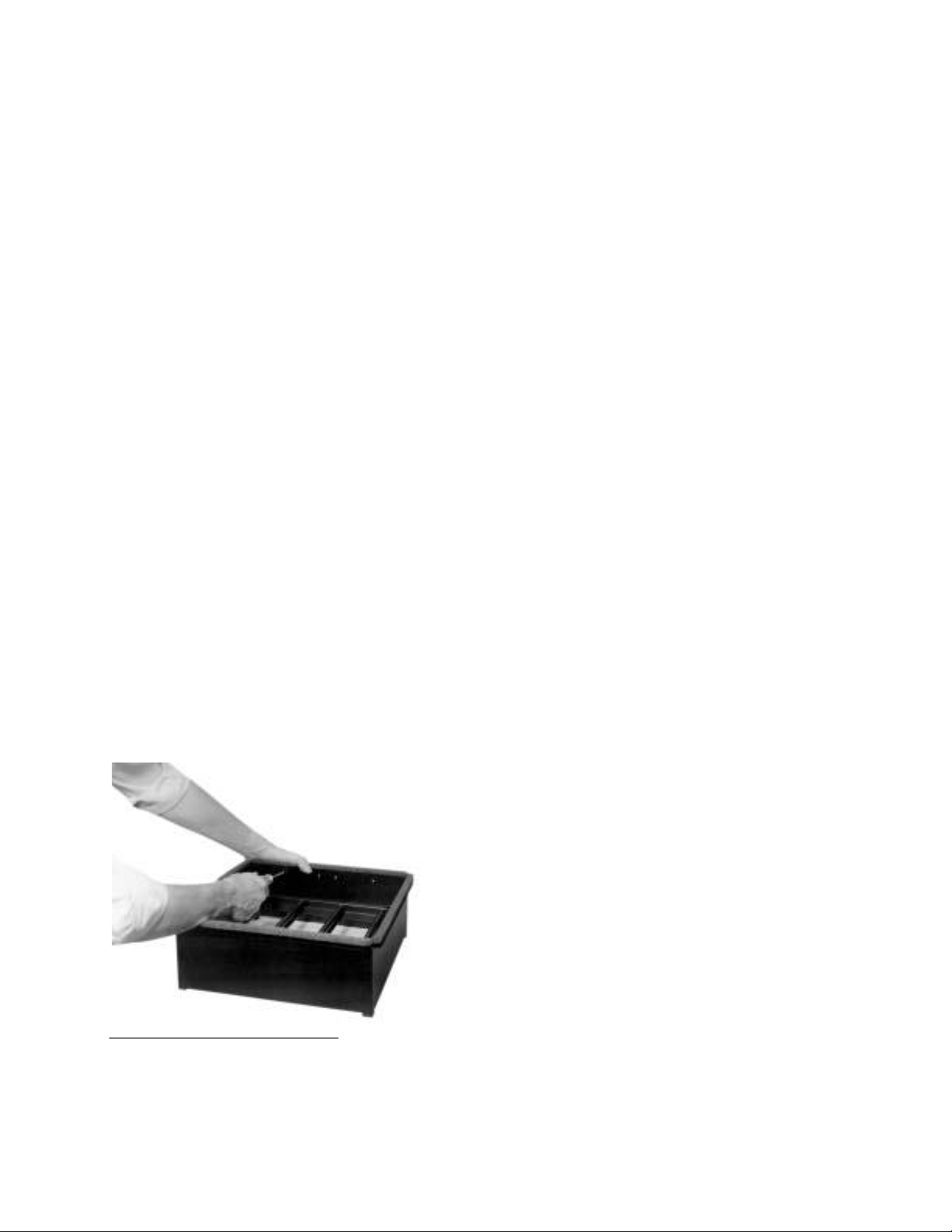
Figure 10: Removing
meter/Range Selector unit
6. Set range selector for low range in proper direction for air flow
through the Balometer Jr. Install LoFlow adapter screen on the side
of the manifold against which the air pressure will be felt.
7. Insert hex adjustment tool into adjustment hole (See Figure 10),
adjust
until
meter reading agrees with wind tunnel setting, and then
remove adjustment tool. Also remove the LoFlow adapter.
8. Move range selector to mid range; set tunnel for 500 cfm (800 cmh,
250 l/s); adjust as in step 7 until meter reading agrees with wind
tunnel setting; then remove adjustment tool.
9. Move range selector to high range; set tunnel for 1200 cfm (2000
cmh, 600 l/s); adjust as in step 7 until meter reading agrees with
wind tunnel setting; then remove adjustment tool.
10. Verify calibration against standard as required.
11. Modify setup so that flow through Balometer Jr. is in opposite
direction. Again make sure there are no leaks in the system.
12. Repeat steps 5 through 10 for air flow in this direction.
Exchange of Calibrated Module
If complete calibration facilities are not available, you may exchange the
range selector/meter assembly for one calibrated at the factory. (See parts
list for proper item number.) You may maintain multiple selector/meter
assemblies if desired, to minimize down time between calibrations. To
separate the selector/meter assembly from the base, remove the
attachment screws (see Figure 10), and then carefully slide the hoses off
the manifold to remove the assembly. The hoses should then be removed
from the selector/meter assembly and saved with the screws for use in
reassembly. To reattach, slide the hoses on the selector/meter assembly
and then gently slide the hoses onto the manifold. Use the screws to
secure the assembly to the base. Make sure that the top manifold hose is
attached to the hose nipple on the range selector closest to the center of
the base. Also examine manifold to verify that there are no cracks or
other sources of leaks.
15

APPENDIX
A:
THEORY OF OPERATION
The Balometer Jr. is an adaptation of the Alnor Balometer and Velometer
Jr. systems which allow this instrument to be used for measurement of air
volume by reading average velocity as the air moves through a cross-
16
section of known constant dimension.
The Balometer Jr. consists of six major subassemblies which function as
a system to provide accurate air flow measurements:
1. Air Collection System—All the air issuing from or entering a
diffuser is collected through a cloth ―hood‖ which is chosen to fit a
specific diffuser at one end, and translates this variable size to a
standard opening which is slightly larger than one foot square. The
diffuser end of this hood is foam-edged to allow for a complete seal
around the opening.
2. Instrument Base—The base, in addition to housing the range
selector, manifold, and Velometer Jr., provides the standard crosssection through which the air is passed.
3. Manifold—This grid contains 16 calibrated holes in a 4 x 4 pattern
spaced within the standard base opening. It is actually two grids
back-to-back, with the pattern of holes in a separate network on each
side. Air can therefore enter the manifold from either side and be
discharged at
the
other. The amount of air which flow through the
manifold is directly proportional to the average velocity of the air
moving past the sensing holes. Therefore this velocity, which is
moving through a known cross-sectional area, is proportional to the
volume of air flow through the instrument.
4. Range Selector—By means of a single control, the range selector
provides for the measurement of air flow in either direction, and
provides calibrated orifices for three ranges, which effectively triples
the scale length of the meter. Accuracy of the measurement in either
direction is assured by providing similar flow paths regardless of
flow direction, and by separate calibration of each range in each
direction.
5. Velometer Jr.—TSI’s standard small swing vane anemometer is
provided with a special scale graduated either in standard cubic feet
per minute or standard cubic meters per hour. Because of the direct
proportion cited earlier, this velocity reading instrument can be
directly calibrated in volumetric terms.

6. LoFlow Adapter—This screen assembly makes use of the standard
area and velocity principles mentioned above. The adapter reduces
the effective area through which the air flows, causing a
corresponding increase in velocity past the manifold. The screen
blocks 50% of the standard
opening, increasing
the velocity to twice
the original. This means, for example, that with the adapter a volume
of 200 cfm will create the same velocity as 400 cfm without the
adapter. The lowest volume range on the Velometer Jr. is calibrated
to be used with the adapter, on the most sensitive range setting.
Note that the adapter provides higher sensitivity at low flow rates, but
can more easily upset the system being measured at flow rates above 125
cfm (200 cmh, 60 l/s) because of additional back pressure. It is therefore
suggested that measurements above these flows be taken without the
adapter.
17

APPENDIX
B:
MAINTENANCE AND TROUBLESHOOTING
18
Maintenance
Hoods
The hoods will last longer if hand washed periodically in cool water
with a mild detergent. When handling do not allow the cloth to come
in
contact with
puncture the material.
Static Electricity
Occasionally static electrical charges may be encountered, especially
in conditions of low humidity. If the Velometer Jr. will not hold a
zero setting, or gives erratic readings, it is suggested that you obtain
anti-static solution for use with the Balometer Jr. The solution may
be obtained from TSI as an accessory (see parts list on inside front
cover). To use, apply with a soft, lint-free cloth slightly moistened
with anti-static solution, rubbing gently over the outside surface of
the Velometer Jr. window.
Manifold
The manifold should be checked before using to be certain that the
sensing holes have not become clogged with dirt or dust particles.
Inspect for cracks which may cause air leaks. Also verify that a good
connection is made between the manifold and the range elector. The
manifold can be cleaned using mild detergent and warm water. Do
NOT immerse the entire manifold in water. It is recommended that
cleaning be done with the manifold in
Zero Adjustment
Periodically check that the Velometer Jr. pointer is at zero when the
range selector is off. If not, use the zero adjustment screw to bring
the pointer to zero in the position the instrument is used.
Calibration
Your Balometer Jr. may be returned to the factory for calibration, or
if proper facilities are available, may be calibrated using the
procedures outlined in the Calibration section of this manual.
When shipping the Balometer Jr. for factory recalibration, pack it
carefully, and follow the Instructions for Return in this manual.
sharp corners or other objects which can tear or
place,
and with extreme care.

Troubleshooting
Symptom
Possible Cause and Corrective
Action
Meter not at zero before use.
Velometer Jr. not adjusted. Use zero
adjustment screw.
Cannot zero meter.
Meter pointer not in balance. Return unit to
factory for rebalance.
Meter reading lower than
expected.
Hood frame not sealing properly around
diffuser or grill. Press hood evenly against
diffuser.
Hood torn. Replace, or repair tear with duct
tape or other non-porous material.
Range selector not properly set. Make sure
detent on switch is properly engaged.
Manifold is cracked. Replace manifold.
Manifold holes are plugged. Clean holes.
Meter/range selector out of calibration.
Recalibrate instrument.
LoFlow adapter not installed when using
lowest (blue) scale. Install adapter.
LoFlow adapter not close enough to
the manifold, or installed on wrong side
of manifold. (See Preparation for Use
section.)
Meter not indicating.
Range selector is switched to OFF. Position
switch to correct range.
Range selector incorrectly set. Position
switch to correct range.
Connection between manifold/range
selector/meter is broken. Repair.
Meter reading higher than
expected.
Meter/range selector out of calibration.
Recalibrate instrument.
LoFlow adapter mistakenly left installed.
19
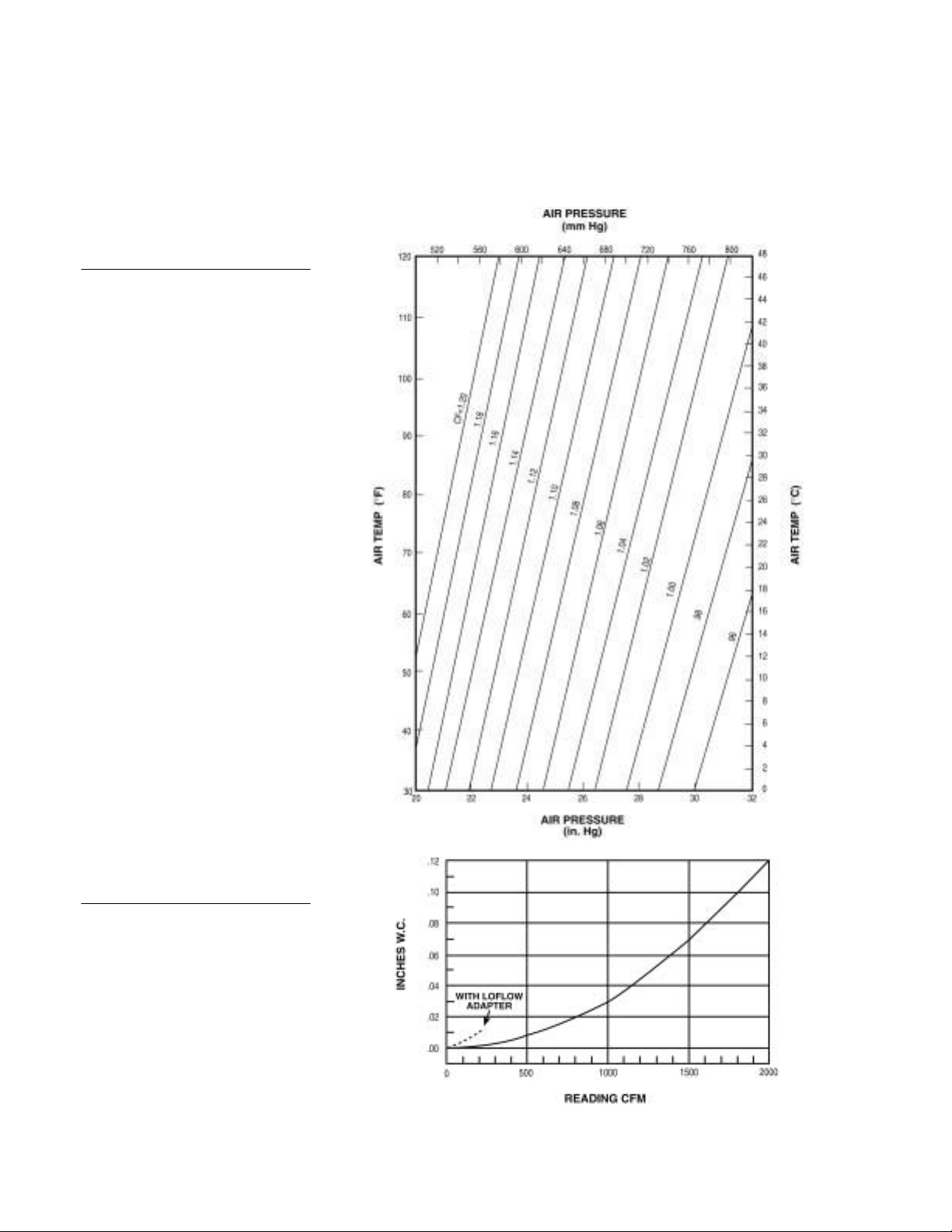
Figure 11: Correction factors for
non-standard conditions
[Note: 1 (in. H20) x 7.36 (10-2)=
1 in. Hg]
Figure 12: Correction factors for
non-standard conditions
20
APPENDIX
FACTORS
STANDARD
C: CORRECTION
FOR NON-
CONDITIONS

REPAIR
INFORMATION
Contact TSI Incorporated before returning your Alnor Instrument to
factory.
See Instructions for Return. Follow the procedure carefully as it
will expedite processing. Failure to follow the procedure will/may cause
return of unit unrepaired. Send your instrument to the factory
transportation prepaid. To assure fast turnaround time, fill out this form
with as much detail as
RMA
Number
possible and
attach it to the instrument.
the
Instrument Model
Serial Number
Date
of
Purchase
Where Purchased
Describe
Malfunction
Describe Environment
Return Instrument to:
Nam
e
(Your name or company)
Address
Telephone
Address Correspondence to:
Name
Address
Telephone
21
 Loading...