

TSI Incorporated AEROTRAK 9306 Operation Manual
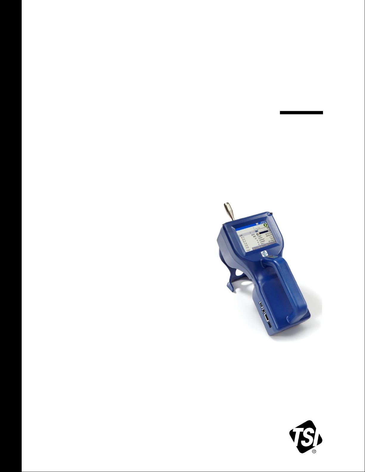
AEROTRAK®
HANDHELD AIRBORNE
PARTICLE COUNTER
MODEL 9306
OPERATION MANUAL
P/N 6004215, REVISION G
JANUARY 2014


SHIP TO/MAIL TO:
TSI Incorporated
500 Cardigan Road
Shoreview, MN 55126-3996
USA
U.S.
Technical Support:
(800) 874-2811/(651) 490-2811
Fax:
(651) 490-3824
E-mail address:
answers@tsi.com
Website:
http://www.tsi.com
INTERNATIONAL
Technical Support:
(001 651) 490-2811
Fax:
(001 651) 490-3824
AEROTRAK®
HANDHELD AIRBORNE
PARTICLE COUNTER
MODEL 9306
OPERATION MANUAL
P/N 6004215, Revision G
January 2014

Manual History
The following is a manual history of the AeroTrak® Handheld Airborne
Particle Counter, Model 9306 Operation Manual (P/N 6004215).
Revision Date
A July 2010
B September 2010
C February 2011
D March 2012
E November 2012
F October 2013
G January 2014
ii

Part Number
6004215 / Revision G /January 2014
Copyright
©TSI Incorporated / 2010-2014 / All rights reserved.
Address
TSI Incorporated / 500 Cardigan Road / Shoreview, MN 55126 / USA
E-mail Address
answers@tsi.com
Limitation of Warranty
and Liability
(effective June 2011)
Seller warrants the goods sold hereunder, under normal use and service as described in the
operator's manual, shall be free from defects in workmanship and material for 24 months, or if
less, the length of time specified in the operator's manual, from the date of shipment to the
customer. This warranty period is inclusive of any statutory warranty. This limited warranty is
subject to the following exclusions and exceptions::
Service Policy
Knowing that inoperative or defective instruments are as detrimental to TSI as they are to our
customers, our service policy is designed to give prompt attention to any problems. If any malfunction is discovered, please contact your nearest sales office or representative, or call TSI’s
Customer Service department at 1-800-874-2811 (USA) or +001 (651) 490-2811
(International).
Warranty
a. Hot-wire or hot-film sensors used with research anemometers, and certain other components
when indicated in specifications, are warranted for 90 days from the date of shipment;
b. Pumps are warranted for hours of operation as set forth in product or operator’s manuals;
c. Parts repaired or replaced as a result of repair services are warranted to be free from defects
in workmanship and material, under normal use, for 90 days from the date of shipment;
d. Seller does not provide any warranty on finished goods manufactured by others or on any
fuses, batteries or other consumable materials. Only the original manufacturer's warranty
applies;
e. Unless specifically authorized in a separate writing by Seller, Seller makes no warranty with
respect to, and shall have no liability in connection with, goods which are incorporated into
other products or equipment, or which are modified by any person other than Seller.
The foregoing is IN LIEU OF all other warranties and is subject to the LIMITATIONS stated
herein. NO OTHER EXPRESS OR IMPLIED WARRANTY OF FITNESS FOR PARTICULAR
PURPOSE OR MERCHANTABILITY IS MADE. WITH RESPECT TO SELLER’S BREACH OF
THE IMPLIED WARRANTY AGAINST INFRINGEMENT, SAID WARRANTY IS LIMITED TO
CLAIMS OF DIRECT INFRINGEMENT AND EXCLUDES CLAIMS OF CONTRIBUTORY OR
INDUCED INFRINGEMENTS. BUYER’S EXCLUSIVE REMEDY SHALL BE THE RETURN OF
THE PURCHASE PRICE DISCOUNTED FOR REASONABLE WEAR AND TEAR OR AT
SELLER’S OPTION REPLACEMENT OF THE GOODS WITH NON-INFRINGING GOODS.
TO THE EXTENT PERMITTED BY LAW, THE EXCLUSIVE REMEDY OF THE USER OR
BUYER, AND THE LIMIT OF SELLER'S LIABILITY FOR ANY AND ALL LOSSES, INJURIES,
OR DAMAGES CONCERNING THE GOODS (INCLUDING CLAIMS BASED ON CONTRACT,
NEGLIGENCE, TORT, STRICT LIABILITY OR OTHERWISE) SHALL BE THE RETURN OF
GOODS TO SELLER AND THE REFUND OF THE PURCHASE PRICE, OR, AT THE OPTION
OF SELLER, THE REPAIR OR REPLACEMENT OF THE GOODS. IN THE CASE OF
SOFTWARE, SELLER WILL REPAIR OR REPLACE DEFECTIVE SOFTWARE OR IF UNABLE
TO DO SO, WILL REFUND THE PURCHASE PRICE OF THE SOFTWARE. IN NO EVENT
SHALL SELLER BE LIABLE FOR LOST PROFITS OR ANY SPECIAL, CONSEQUENTIAL OR
INCIDENTAL DAMAGES. SELLER SHALL NOT BE RESPONSIBLE FOR INSTALLATION,
DISMANTLING OR REINSTALLATION COSTS OR CHARGES. No Action, regardless of form,
may be brought against Seller more than 12 months after a cause of action has accrued. The
goods returned under warranty to Seller's factory shall be at Buyer's risk of loss, and will be
returned, if at all, at Seller's risk of loss.
Buyer and all users are deemed to have accepted this LIMITATION OF WARRANTY AND
LIABILITY, which contains the complete and exclusive limited warranty of Seller. This
LIMITATION OF WARRANTY AND LIABILITY may not be amended, modified or its terms
waived, except by writing signed by an Officer of Seller.
iii

Trademarks
AeroTrak and TRAKPRO are trademarks of TSI Incorporated. TSI and the TSI logo are
registered trademarks of TSI Incorporated. Microsoft and Excel are registered trademarks of
Microsoft Corporation. OpenOffice is a trademark of Sun Microsystems. Modbus® is a
registered trademark of Modicon, Inc.
iv AeroTrak® Handheld Airborne Particle Counters

Contents
Manual History ............................................................................................ ii
Warranty ..................................................................................................... iii
Safety Information .................................................................................... vii
Laser Safety ......................................................................................... vii
Labels ................................................................................................... viii
Description of Caution/Warning Symbols ............................................. ix
Caution ............................................................................................... ix
Warning .............................................................................................. ix
Caution or Warning Symbols ............................................................. ix
Getting Help ........................................................................................... x
CHAPTER 1 Introduction and Unpacking ............................................. 1-1
Unpacking the AeroTrak
Optional Accessories ....................................................................... 1-3
CHAPTER 2 Getting Started ................................................................... 2-1
Instrument Description ........................................................................ 2-1
Using the Instrument Stand and Stylus ............................................... 2-2
Providing Power .................................................................................. 2-3
To Install the Lithium-Ion Battery ..................................................... 2-3
To Use AC Power ............................................................................ 2-4
Using with a Printer ............................................................................. 2-4
Installing an Isokinetic Inlet ................................................................. 2-5
Installing a Temperature/Relative Humidity Probe ............................. 2-6
CHAPTER 3 Operation ............................................................................ 3-1
Screen Layout and Functionality ......................................................... 3-1
Software Input Panel (Keyboard or Keypad) ................................... 3-2
Main Tab .......................................................................................... 3-2
Zoomed Data Screen ................................................................... 3-5
Setup Tab ........................................................................................ 3-6
Zone Setup Screen ....................................................................... 3-7
Recipes Setup Screen ................................................................ 3-11
System Setup Screen ................................................................. 3-16
Change Power On Password Screen ......................................... 3-17
Change Setup Password Screen ............................................... 3-18
Configuration Screen .................................................................. 3-19
Print Setup Screen ..................................................................... 3-20
Print Schedule Screen ................................................................ 3-21
Clear Samples Screen................................................................ 3-22
Device Setup Screen .................................................................. 3-22
Date and Time Screen ................................................................ 3-23
Display Screen ........................................................................... 3-24
Information Screen ..................................................................... 3-24
Communication Screen .............................................................. 3-25
Regional Screen ......................................................................... 3-26
®
Handheld Airborne Particle Counter .......... 1-2
v

Environment Screen ................................................................... 3-27
Data Tab ........................................................................................ 3-28
Export Data Screen .................................................................... 3-30
Print Data .................................................................................... 3-34
Reports Tab ................................................................................... 3-36
CHAPTER 4 Data Handling ..................................................................... 4-1
USB Data Download ........................................................................... 4-1
USB Computer Communication .......................................................... 4-2
Installing Software ............................................................................... 4-2
Ethernet Communications ................................................................... 4-2
CHAPTER 5 Maintenance ....................................................................... 5-1
Maintenance Schedule ........................................................................ 5-1
Zero Check .......................................................................................... 5-1
Cleaning the Instrument Enclosure ..................................................... 5-1
CHAPTER 6 Troubleshooting ................................................................. 6-1
CHAPTER 7 Contacting Customer Service ........................................... 7-1
Technical Contacts .............................................................................. 7-1
International Contacts ...................................................................... 7-1
Service .......................................................................................... 7-1
Technical Support ......................................................................... 7-2
Returning the AeroTrak® Handheld Airborne Particle Counter
for Service ........................................................................................ 7-3
APPENDIX A Specifications .................................................................. A-1
Temperature/RH Probe (700084) Specifications
(optional accessory) ........................................................................ A-2
Compliance ........................................................................................ A-3
Dimensional Diagram ......................................................................... A-3
Index
vi AeroTrak® Handheld Airborne Particle Counter
Laser Safety
W A R N I N G
The use of controls, adjustments, or procedures other than those
specified in this manual may result in exposure to hazardous optical
radiation.
Safety Information
This section gives instructions to promote safe and proper handling of the
AeroTrak® Handheld Airborne Particle Counters.
I M P O R T A N T
There are no user-serviceable parts inside the instrument. Refer all repair
and maintenance to a qualified factory-authorized technician. All
maintenance and repair information in this manual is included for use by
a qualified factory-authorized technician.
The Model 9306 Handheld Airborne Particle Counter is a Class I
laser-based instrument.
During normal operation, you will not be exposed to laser radiation.
Precaution should be taken to avoid exposure to hazardous radiation
in the form of intense, focused, visible light.
Exposure to this light may cause blindness.
Take these precautions:
DO NOT remove any parts from the particle counter unless you are
specifically told to do so in this manual.
DO NOT remove the housing or covers. There are no user-
serviceable components inside the housing.
vii
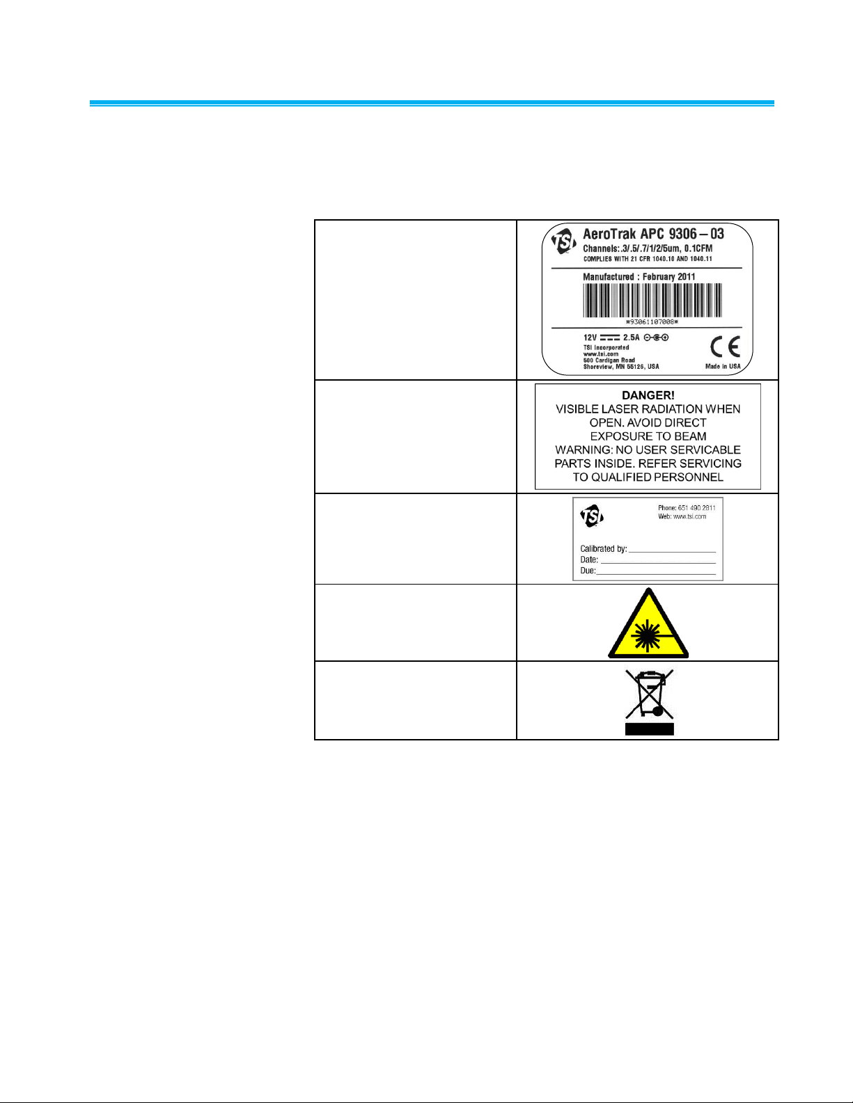
Labels
1. Serial number label (back
panel)
2. Laser radiation label
(internal)
3. Calibration Label
(side panel)
4. Laser radiation symbol
label (internal)
5. European symbol for nondisposable item. Item must
be recycled.
Advisory labels and identification labels are attached to the outside of the
particle counter housing and to the optics housing on the inside of the
instrument.
viii AeroTrak® Handheld Airborne Particle Counter
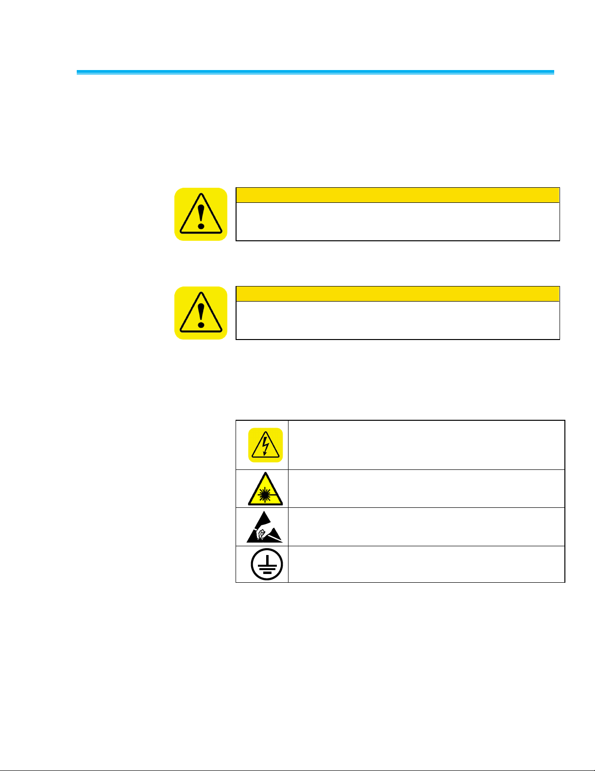
Description of Caution/ Warning Symbols
C a u t i o n
Failure to follow the procedures prescribed in this manual might result in
irreparable equipment damage. Important information about the operation
and maintenance of this instrument is included in this manual.
W A R N I N G
Warning means that unsafe use of the instrument could result in serious
injury to you or cause damage to the instrument. Follow the procedures
prescribed.
Warns that uninsulated voltage within the instrument may
have sufficient magnitude to cause electric shock. Therefore,
it is dangerous to make contact with any part inside the
instrument.
Warns that the instrument contains a laser and that important
information about its safe operation and maintenance is
included in the manual.
Warns that the instrument is susceptible to electro-static
dissipation (ESD) and ESD protection procedures should be
followed to avoid damage.
Indicates the connector is connected to earth ground and
cabinet ground.
Appropriate caution/warning statements are used throughout the manual
and on the instrument that require you to take cautionary measures when
working with the instrument.
Caution
Warning
Caution or Warning Symbols
The following symbols may accompany cautions and warnings to indicate
the nature and consequences of hazards:
Safety Information ix

Getting Help
To obtain assistance with this product or to submit suggestions, please
contact Customer Service:
TSI Incorporated
500 Cardigan Road
Shoreview, MN 55126 U.S.A.
Fax: (651) 490-3824 (USA)
Fax: 001 651 490 3824 (International)
Telephone: 1-800-874-2811 (USA) or (651) 490-2811
International: 001 651 490 2811
E-mail Address: answers@tsi.com
Web site: www.tsi.com
x AeroTrak® Handheld Airborne Particle Counter

Model
Size Range
9306-03
0.3, 0.5, 0.7, 1.0, 2.0, 5.0 μm
9306-04
0.3, 0.5, 1.0, 3.0, 5.0, 10.0 μm
9306-V2
0.3 to 10 μm, user-selectable; factory-calibrated at 0.3, 0.5,
1.0, 3.0, 5.0, 10.0 μm
C H A P T E R 1
Introduction and
Unpacking
The AeroTrak® Model 9306 Airborne Particle Counter (particle counter) is
a lightweight, handheld particle counter with a touch-screen interface. It
operates on the included lithium-ion battery or AC power.
This device has a 0.1 CFM (2.83 L/min) flow rate and counts bin sizes
from 0.3 to 25 µm that depend on the model ordered (see table below).
Up to 10,000 data sets can be downloaded for analysis and reporting
using the TrakPro™ Lite Secure Data Download Software included with
the device.
Typical applications for this particle counter include clean room
monitoring, research, exposure assessment, indoor air quality, filter
testing, clearance testing, quality assurance, and contaminant migration
studies. All AeroTrak
®
particle counters meet JIS standards.
(continued on next page)
1-1
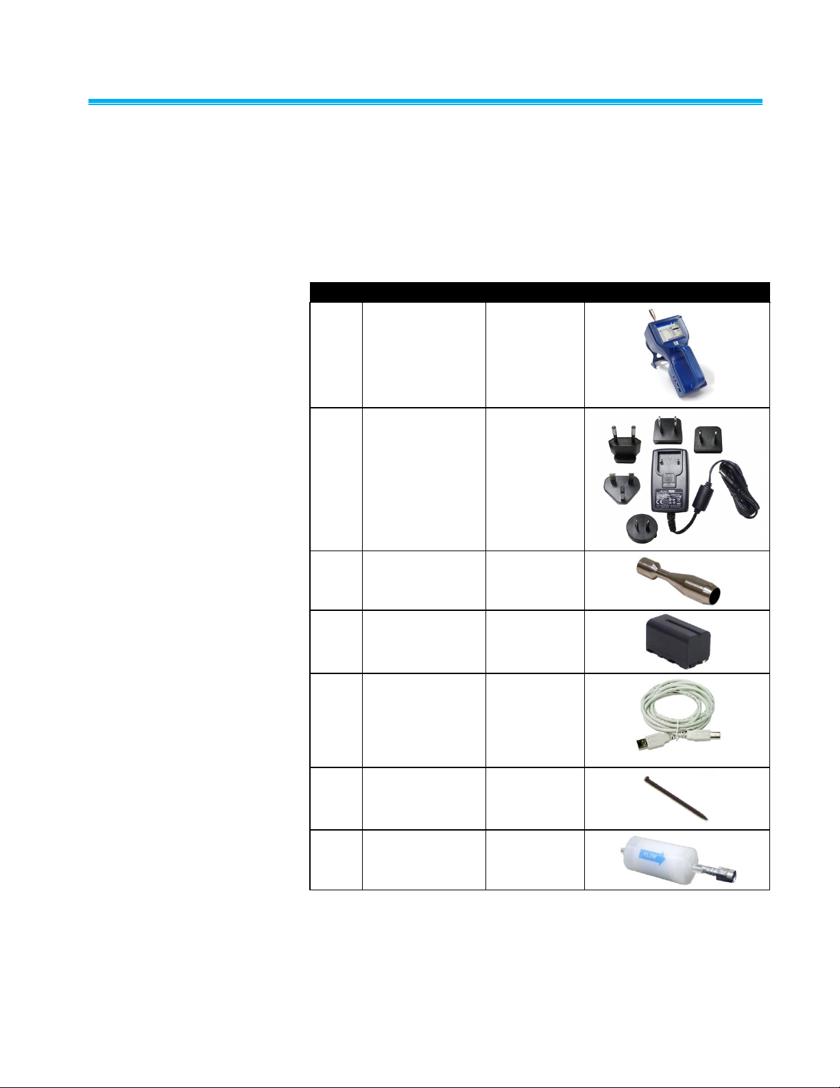
Unpacking the AeroTrak
Qty.
Item Description
Part/Model
Reference Picture
1
AeroTrak® Airborne
Particle Counter
9306-03
9306-04
9306-V2
1
Power Supply with
universal plugs
801694
1
Isokinetic inlet
700003 AL
1
Battery pack
700032
1
Computer cable
(2 m), USB A to B
700033
1
Stylus
N/A
1
HEPA zero filter
assembly
700005
®
Handheld
Airborne Particle C ounter
Carefully unpack the AeroTrak® Airborne Particle Counter from the
shipping container and verify that all the items shown in the photos below
and listed in the following tables are present. Contact TSI immediately if
items are missing or broken.
Model 9306 AeroTrak® Airborne Particle Counter Parts List
1-2 AeroTrak® Handheld Airborne Particle Counter
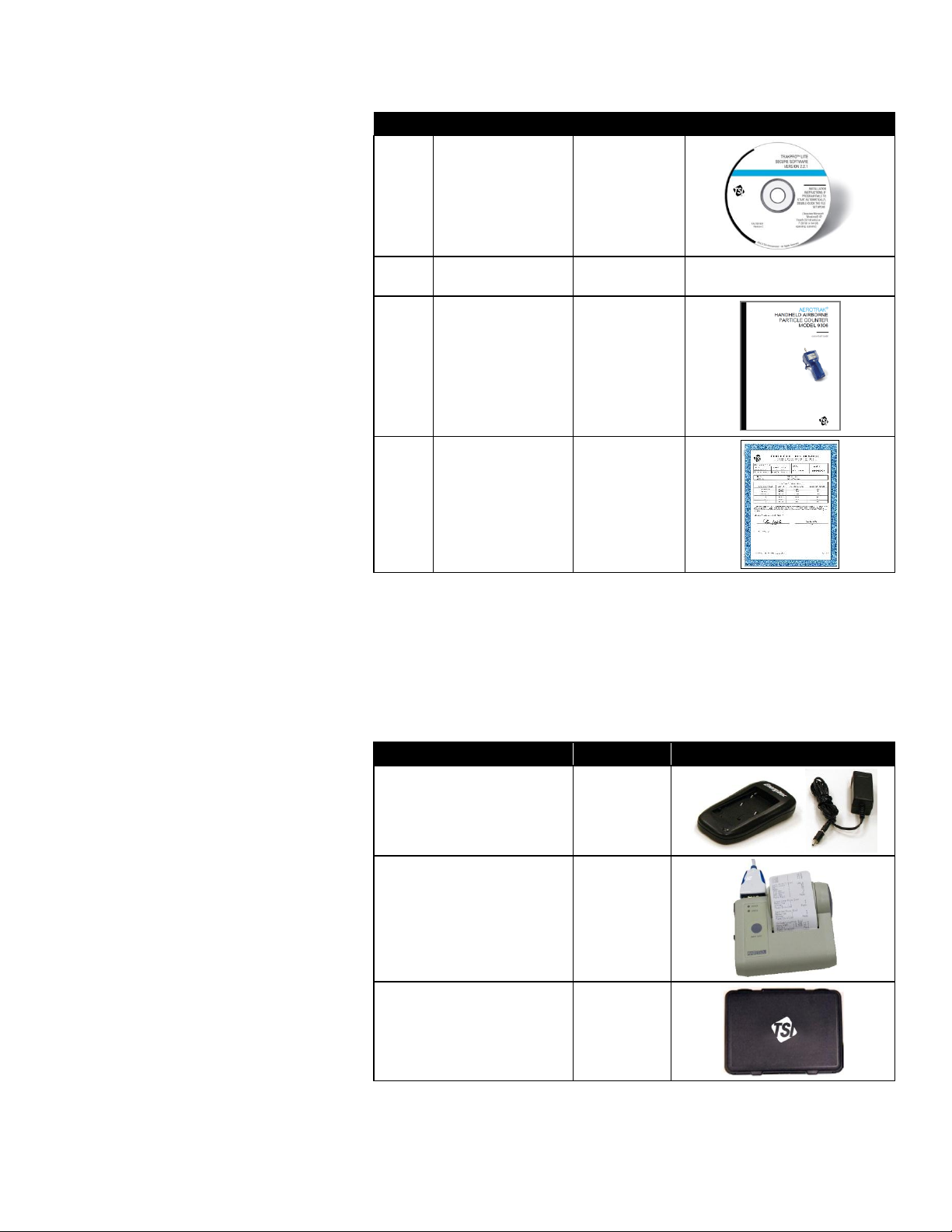
Qty.
Item Description
Part/Model
Reference Picture
1
TrakPro™ Lite
Secure Software
CD for 21 CFR Part
11 compliant data
downloading
(includes manuals)
7001901
1
Operation Manual
6004215
Included on TrakPro™ Lite
Secure Software CD
1
Quick Start Guide
6004216
1
Calibration
certificate
N/A
Optional Accessories
Item Description
Part/Model
Reference Picture
External battery charger with
AC adapter and power cord
700025
External Printer
700085
Carry case
700083
The following photos and table list optional accessories. If you ordered
optional accessories, make certain they have been received and are in
working order.
Model 9306 AeroTrak® Airborne Particle Counter Optional Accessories
Introduction and Unpacking 1-3
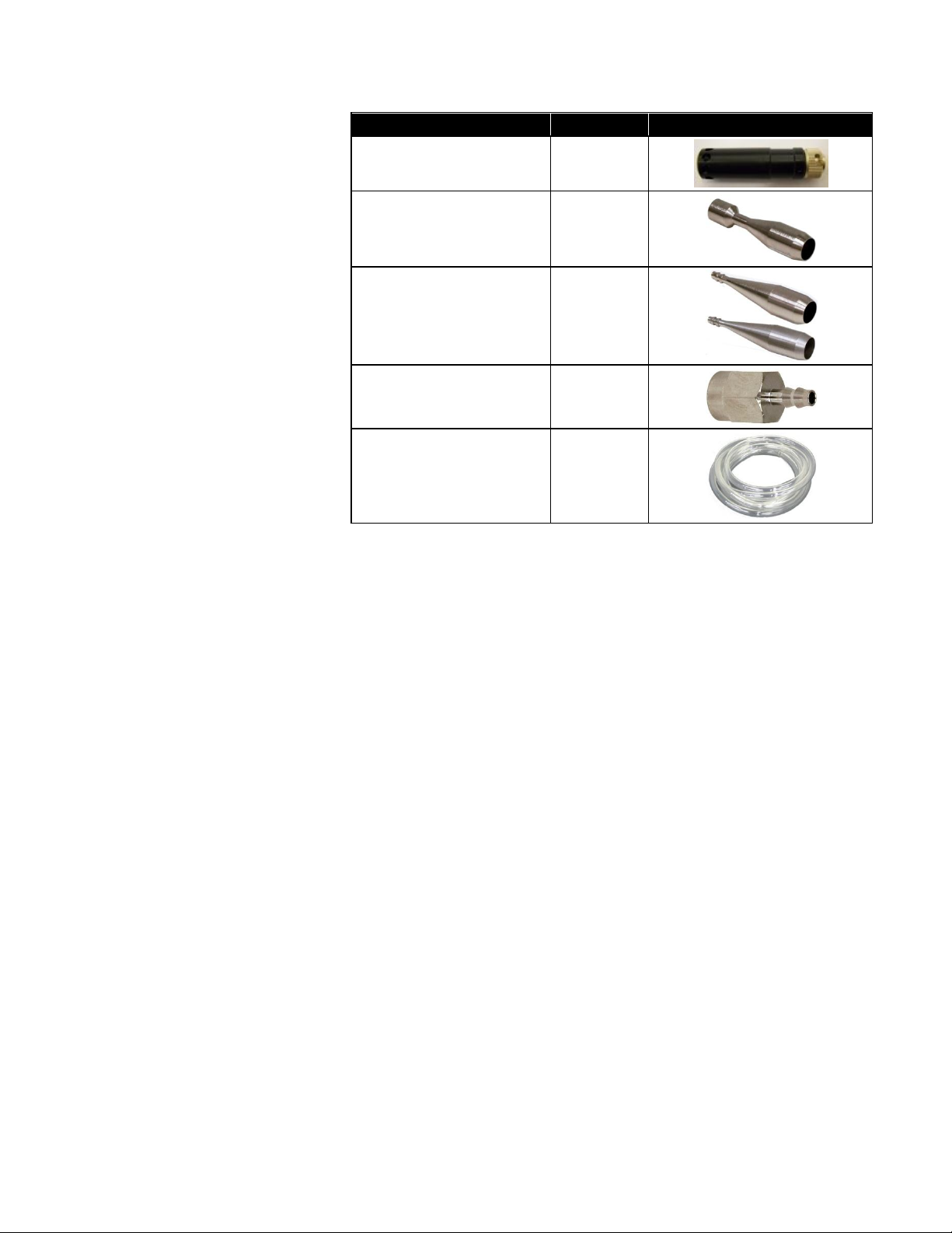
Item Description
Part/Model
Reference Picture
Temperature/humidity probe
700084
Stainless Steel Isokinetic
inlet
700004
Isokinetic probe (used with
tubing)
700001 AL
700002 SS
0.1 cfm Barb Inlet Fitting
700020
Tubing, Superthane 1/8-inch
ID x ¼-inch OD, Clear 100 ft
700009
1-4 AeroTrak® Handheld Airborne Particle Counter
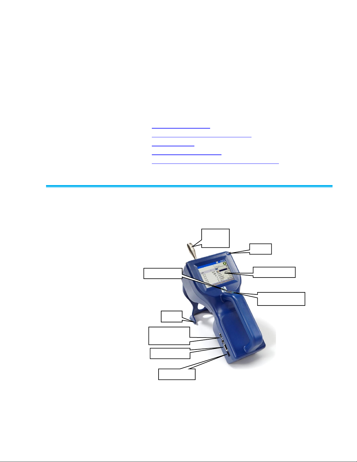
Isokinetic
Inlet
Touch-Screen
USB Host and
Device Ports
Stand
Power Button
Start Sample
Stylus
Power Entry
Ethernet Port
C H A P T E R 2
Getting Started
This chapter provides information to help you use the Model 9306
AeroTrak® Handheld Airborne Particle Counter including:
Instrument Description
Using the Instrument Stand and Stylus
Providing Power
Installing an Isokinetic Inlet
Installing a Temperature/Relative Humidity Probe
Instrument Description
The Model 9306 has many features to make measurements convenient.
They are described in detail below.
2-1
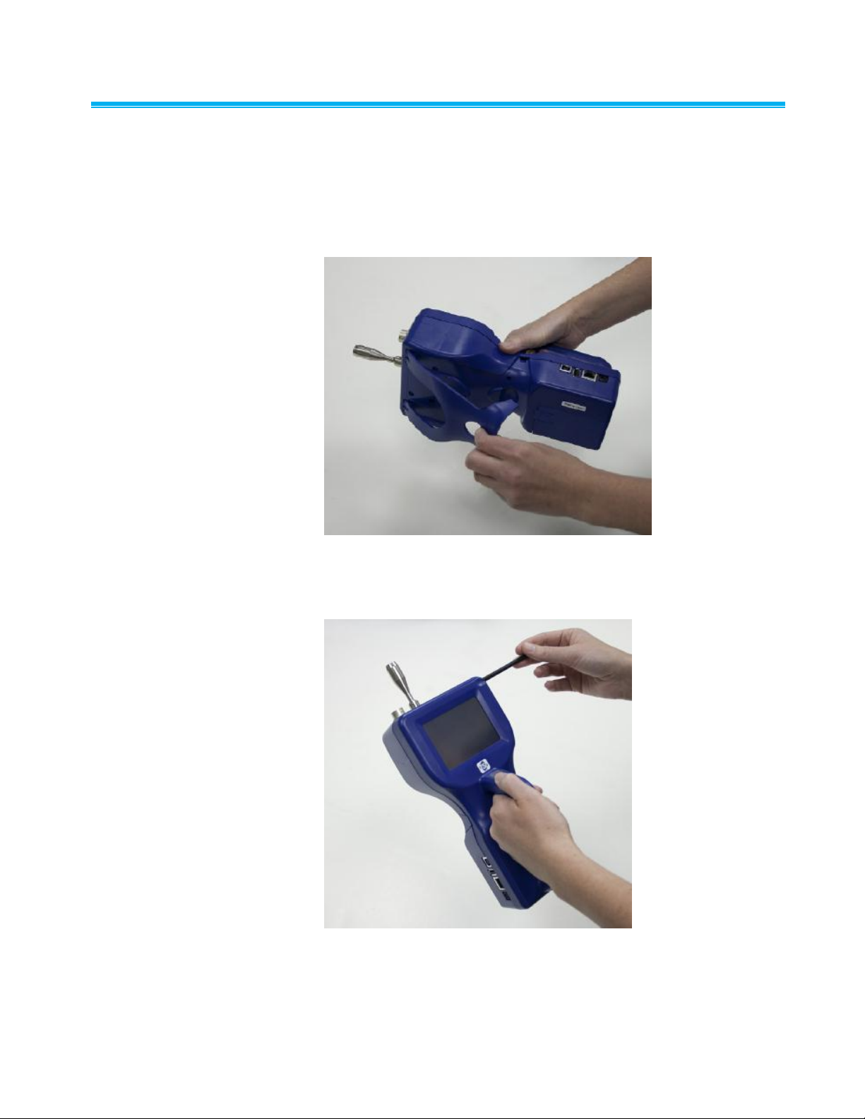
Using the Instrument S t and and Stylus
The Model 9306 is equipped with an integral instrument support stand.
To open the stand, grasp it by the large finger hole and pull it out until it
locks into place. Be careful not to overextend the stand. To store the
stand out of the way when not in use, simply push the stand back until it
snaps into place.
The Model 9306 is also equipped with a plastic stylus for use with the
touch screen interface. The stylus locks into place in the case near the
top of the unit when not in use.
2-2 AeroTrak® Handheld Airborne Particle Counter
Providing Power
W A R N I N G
The battery supplied by TSI (PN 700032) has built in protection against
explosion and fire hazard. Do not use a substitute.
W A R N I N G
Do not use non-rechargeable batteries in this instrument. Fire,
explosions, injury or other hazards may result.
The Model 9306 may be powered using a rechargeable lithium-ion
battery, or through an AC power cord.
NOTES:
When using AC power, the battery (if installed) charges when the
instrument is on, but not while actively sampling.
Removing/changing the lithium-ion battery or disconnecting AC
power does not cause loss of data.
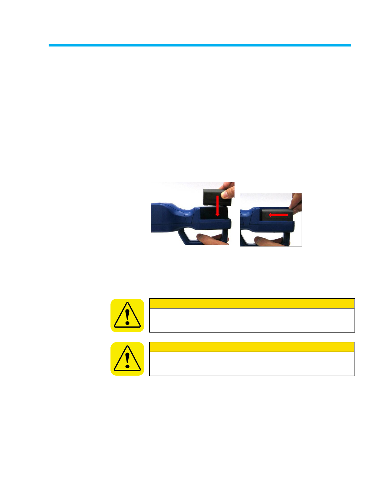
To Install the Lithium-Ion Battery
1. Remove the battery cover from the back of the instrument by lightly
depressing the textured tab on the cover located on the lower left.
2. Place the lithium-ion battery into the battery compartment and slide it
forward (toward the top of the unit) until it locks into place.
3. Replace the battery cover and slide it in place until you hear a click.
Getting Started 2-3
To Use AC Power
1. Connect the AC power adapter to the power cord.
2. Insert the AC power adapter into the side of the Model 9306.
3. Connect the power cord to an outlet.
4. Press the on/off button (located on the front of the instrument
handle).
5. After a splash screen displays the TSI logo, a brief start-up sequence
begins as the Windows® CE operating system boots up.
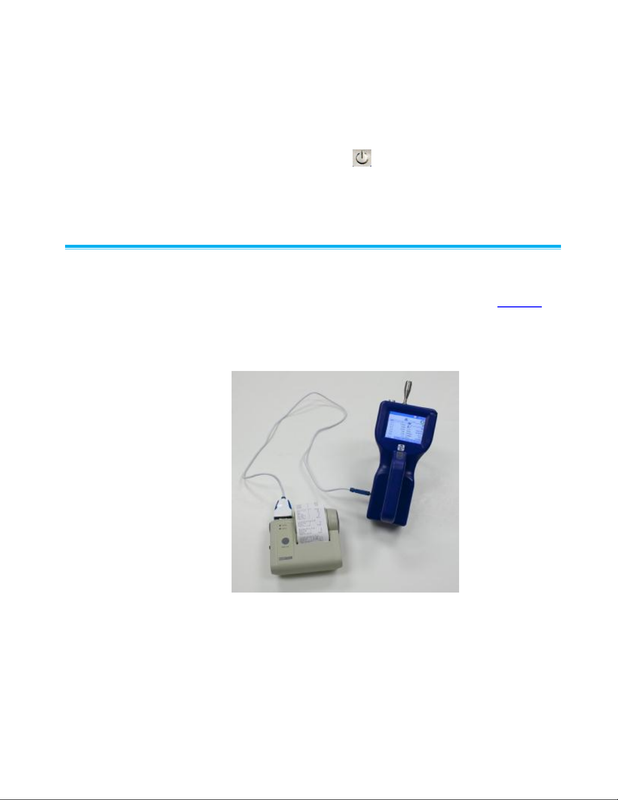
Using with a Printer
A hard copy of a sample set can be printed from the instrument using the
optional TSI Model 700085 thermal printer (see Chapter 3, “Operation”).
Only the TSI Model 700085 printer is compatible with the Model 9306.
The printer may be used on its internal battery or an AC adapter. A
custom communications cable is included with the printer. The cable
goes between the USB A port and the 9 pin DSUB on the printer.
2-4 AeroTrak® Handheld Airborne Particle Counter
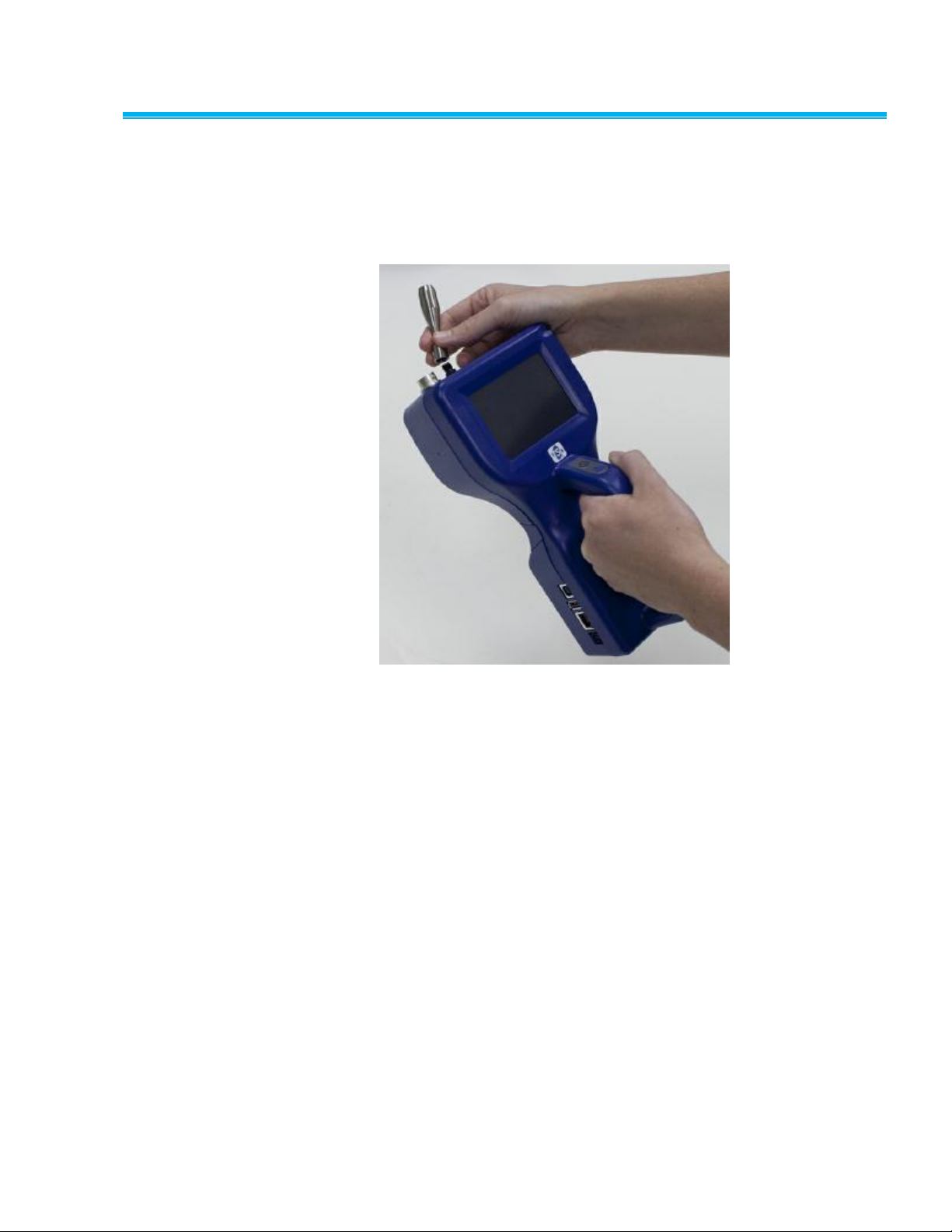
Installing an Isokinet i c In l e t
The Isokinetic inlet smoothly accelerates air into the inlet of the
instrument. To install, simply thread the inlet directly onto the inlet nozzle
until finger tight. The inlet seals over an O-ring so it doesn’t have to be
very tight to seal.
Getting Started 2-5
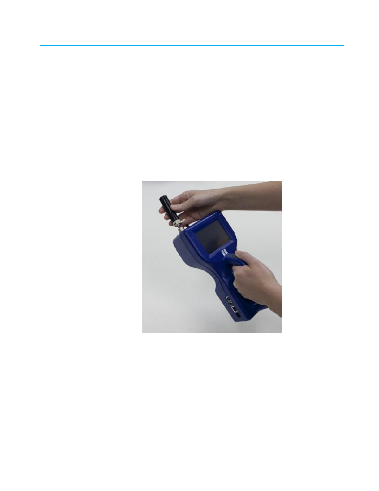
Installing a Temperatu r e/Relative Humidity Probe
To install the optional temperature/relative humidity probe:
1. Align the probe so the pins slide into the sockets of the base
connector.
2. Align the locking collar on the probe so it will slide over the alignment
pins on the base connector
3. Press down and turn the locking collar to lock in the probe.
4. Temperature and relative humidity are automatically displayed in the
upper-left corner.
5. Remove the probe by turning the locking collar and then pulling
straight up on the probe.
2-6 AeroTrak® Handheld Airborne Particle Counter
C H A P T E R 3
Operation
The Model 9306 AeroTrak® Handheld Airborne Particle Counter is
controlled using a touch screen display. Use the plastic stylus or your
finger tip. DO NOT use sharp objects (such as a pen point) that may
damage the screen overlay.
To turn on the instrument, press the on/off button (located in the center
of the front of the instrument). After a splash screen displays the TSI
logo, a brief start-up sequence begins as the Windows® CE operating
system boots up.
The instrument is ready for operation when the main tab (shown below)
appears. If an optional temperature/humidity probe is attached, those
values will be shown in the upper-left corner also.
Screen Layout and Fun c tionality
There are four main screens (tabs): Main, Setup, Data, and Reports. The
operation of each of these screens, the information displayed on them,
and the operations you can perform from each are described in the
remainder of this chapter.
Some screens require or allow you to enter information. To enter
information, tap on the screen and an on-screen keyboard appears.
3-1

Software Input Panel (Keyboard or Keypad)
1. Throughout the setup screens, a keyboard or keypad appears on the
screen when text or numbers may be entered.
2. When you enter information using the keyboard, press either the
(Enter) or Esc keys when you are done. When you enter data using
the keypad, the data is entered when you press OK on the screen.
The keyboard will then be hidden until another text entry box is
selected.
3. When numeric input is required, a numeric keypad will appear on the
screen in place of the full keyboard.
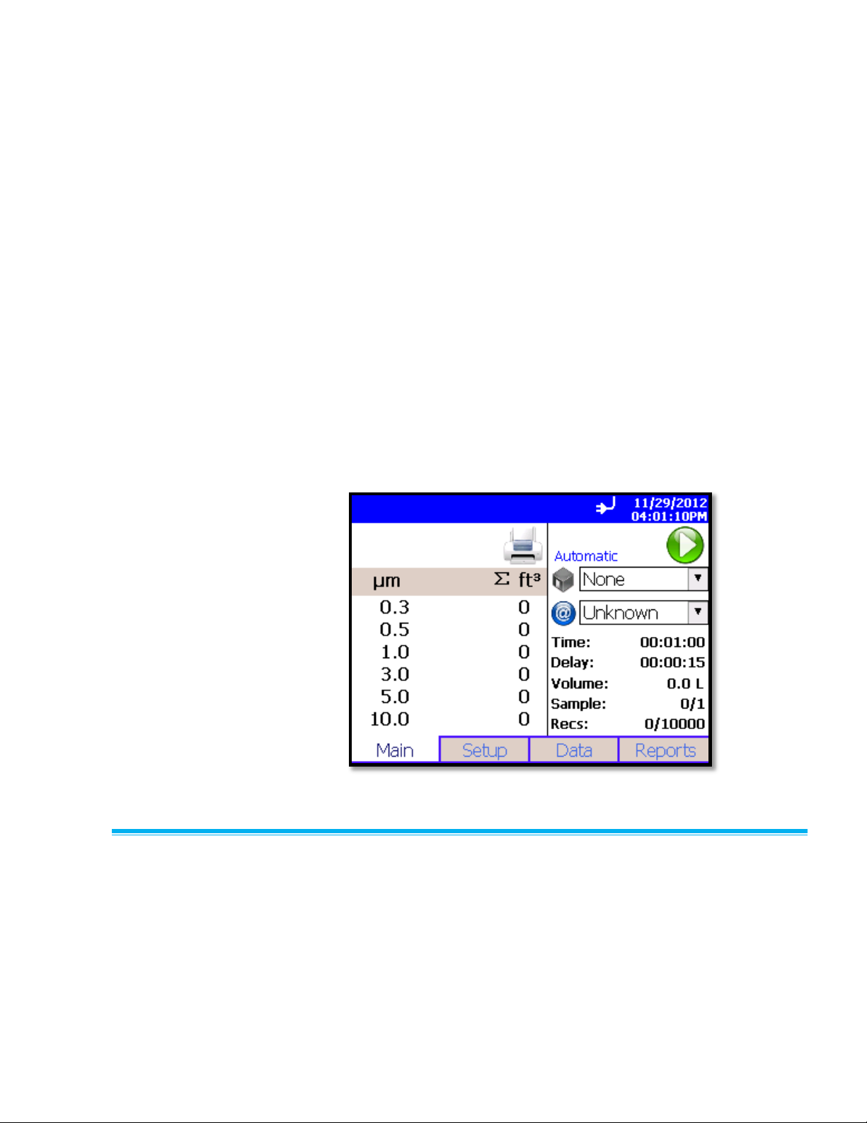
Main Tab
The Main Tab is the default screen. The left side of the screen
summarizes the concentrations for the currently selected location. Tap on
the size and count portion of the screen to enable Zoomed Data Screen
(see Setup Tab).
The display shows:
Temperature*
Relative humidity*
Bin sizes
Particle count/concentration
The status bar at the top of the screen shows the current time and date
(see the Setup Tab) and indicates:
*
Temperature and Humidity are displayed only if the optional T/H probe is installed.
3-2 AeroTrak® Handheld Airborne Particle Counter
 Loading...